Article

Tribological Characterization of Polyether Ether Ketone (PEEK) Polymers Produced by Additive Manufacturing for Hydrodynamic Bearing Application

1
Department of Mechanical Engineering, Politecnico di Milano, Via G. La Masa 1, 20156 Milan, Italy
2
Eurobearings S.R.L., 29016 Cortemaggiore, Italy
*
Author to whom correspondence should be addressed.
Lubricants 2021, 9(11), 112; https://doi.org/10.3390/lubricants9110112
Submission received: 20 September 2021 / Revised: 9 November 2021 / Accepted: 18 November 2021 / Published: 21 November 2021

Abstract

:
The coating materials commonly used in hydrodynamic bearings are the so-called “Babbitt metals” or “white metals”, as defined by ASTM B23-00. Their low Young’s modulus and yield point have encouraged researchers to find new coatings to overcome these limitations. In this paper, the friction and wear of PEEK are studied in a dry sliding environment (without lubrication) using a ball-on-disk tribometer and compared to those of Babbitt metal. Furthermore, the bond strength tests between PEEK and metals/alloys are evaluated. PEEK polymer samples were obtained from cylindrical rods, manufactured by an innovative process for polymer bonding on bearing surfaces, using additive manufacturing technology. The morphologies of the degraded surfaces were examined using a high-resolution metallurgical optical microscope (OM) and a scanning electron microscope (SEM). The coefficients of friction (CoF) were obtained under the alternating ball-on-disk dry tribometer. The results of the experimental activity show that PEEK polymers have CoFs of about 0.22 and 0.16 under the 1 and 5 N applied load, respectively. The CoF and wear volume loss results are reported and compared to the reference Babbitt coating.

Graphical Abstract

1. Introduction

Rotating machines, especially turbines, have had considerable technological evolution since their introduction. Neglecting the historical testimonies that would trace their origin back to Heron of Alexandria from the first century BC [1], the modern steam turbine was invented in 1884 by Charles Parsons [2]. His patent was licensed and the turbine scaled by George Westinghouse. However, not all the components that compose the rotating machines have undergone technological evolution; in particular, the materials used in bearings differ little from those used in pioneering applications, see for example [3].
The parts of the bearings that may come into direct contact with the shaft are coated with a sacrificial material, which must have two fundamental characteristics: a low coefficient of friction and hardness lower than that of the shaft.
The coating material commonly employed is called “Babbitt metal” based on tin and differentiate for the percentages of other elements, mainly antimony and copper, and a non-negligible percentage of lead. For environmental reasons white metal alloys no longer contain lead, cadmium, nickel, and arsenic, but generally retain the same mechanical properties [4]. As mentioned, white metals do not have to be particularly hard, but this means that they have a rather low Young’s modulus, as well as a low yield point that is about 45.5 MPa at 20 °C and decreases to almost half at 100 °C.
These features limit the so-called “average specific load” of bearings (i.e., the ratio of the load to the active bearing surface) to values between 2 and 3 MPa, to prevent wiping and damage to the bearing surface.
The low average specific load has in recent years encouraged research aimed at replacing white metal with materials with the same or better antifriction characteristics, but with a higher yield point. Some attempts have been made public (see e.g., [5,6,7]) using polymers. The use of polytetrafluoroethylene (PTFE) was initially attempted, but PTFE is not very suitable because it presents the phenomenon of dishing or crowning (see e.g., [8,9]), which leads to an unacceptable permanent distortion of the bearing surface. A better candidate appears to be polyether-ether-ketone (PEEK), according to preliminary studies presented in [3].
PEEK is a technology advanced semicrystalline thermoplastic polymer. It is used in the food processing, aerospace, electronics and semiconductor, oil and gas, and automotive industries [10], nuclear and hydroelectric [11], vacuum technology, medical (dental field—sometimes used instead of titanium), and for the production of cables.
In this experimental work, PEEK-based coatings for hydrodynamic bearings were analyzed for their tribological properties and compared with those of Babbitt metal. Few reports are available in the literature on the tribology and wear for PEEK-based coatings for bearing pads. One of the challenges of polymer-coated bearing pads is the cost-effective manufacturing of a reliable bonding between the polymeric sliding layer and the thick-walled steel support of the pads. This bonding must be reliable and last, possibly, for the lifetime of the plant.
Various positive-locking methods were developed in the past to solve this task. These include the attachment of an intermediate layer of wire mesh to the steel support body [12] or the sinter-fusing of a thin intermediate layer of bronze to the steel support. The latter was developed in 1956 by the GGB Company (GGB, France) [13]. Tin bronze is sintered in powder form with a thickness of 0.3–1 mm at a temperature of around 900 °C. This creates an open-pore structure with undercuts that facilitates adhesion of the polymer and then permanently bonded. Another technique was developed by Renk AG in collaboration with Fraunhofer Institute of Laser Technology—ILT [14]. In this case, the advantages of selective laser melting 3D printing are exploited to build directly on the pad support a layer with undercuts where the PEEK polymer can be bonded through hot pressing. Finally, a different technique has been developed by GE Renewables, in which the PEEK layer and the metal backing support are not bonded together, but are mechanically jointed, allowing easy maintenance [15].
A new technique has been introduced in a recent patent [16] and exploits the advantages of screw-extrusion (fused deposition modeling—FDM) additive manufacturing to create a coating [17] on a metal backing plate/cylinder/pad. In this case, the advantages of FDM additive manufacturing [18,19] are the following: better control of the material properties, material saving, and the possibility to create a layout and shapes not possible for other technologies. By controlling the cooling rate, it is possible to favor the presence of amorphous and/or crystalline material, by suitably varying the properties of the material. The experimental tests described in this paper are aimed at characterizing the PEEK coatings [20,21] employed in this last technique.
In general, PEEK polymers have good wear resistance, especially when encountering high loads and poor lubrication environments. The main characteristics of this polymer are high strength and stiffness, excellent resistance to both high and low temperatures, excellent wear resistance, low flammability, and low tendency to deformation. PEEK combines excellent mechanical characteristics to extraordinarily wide operating conditions.
The addition of small amounts of reinforcements, such as carbon fiber [22,23] and solid lubricants such as PTFE and graphite, improves both the mechanical and the tribological properties of PEEK polymers [24,25]. The heat treatment increases the hardness capacity and tensile strength of PEEK-based polymers [26].
The main problems in bearing coatings/layers are related to the bonding strength, the maximum allowable working temperature, wear that can occur in dry/mixed lubrication, and possible thermal creep phenomena. The use of PEEK will be examined in detail, focusing on its characteristics in terms of CoF and adhesion to the metal of the pads of tilting-pad journal bearings [17] (TPJBs), a particularly critical aspect that has so far prevented widespread dissemination of this material, despite being proposed almost 35 years ago [27] for this application. In this research work, the bonding issue is briefly analyzed because it is a well-known problem solved by the bearing manufacturers by satisfying the procedure and tests described by the international standards (ISO 4386-2). The attention is focused more on the more interesting tribological problem.
In this paper, the characterization of both PEEK and Babbitt metal in terms of coefficient of friction (CoF) has been done by using ball-on-disk (BOD) tests, with small applied load values (1 and 5 N) under sliding mode, for dry wear conditions. Finally, the morphologies of the worn surfaces have been examined using a scanning electron microscope (SEM) and a high-resolution metallurgical optical microscope (OM).

2. Materials and Methods

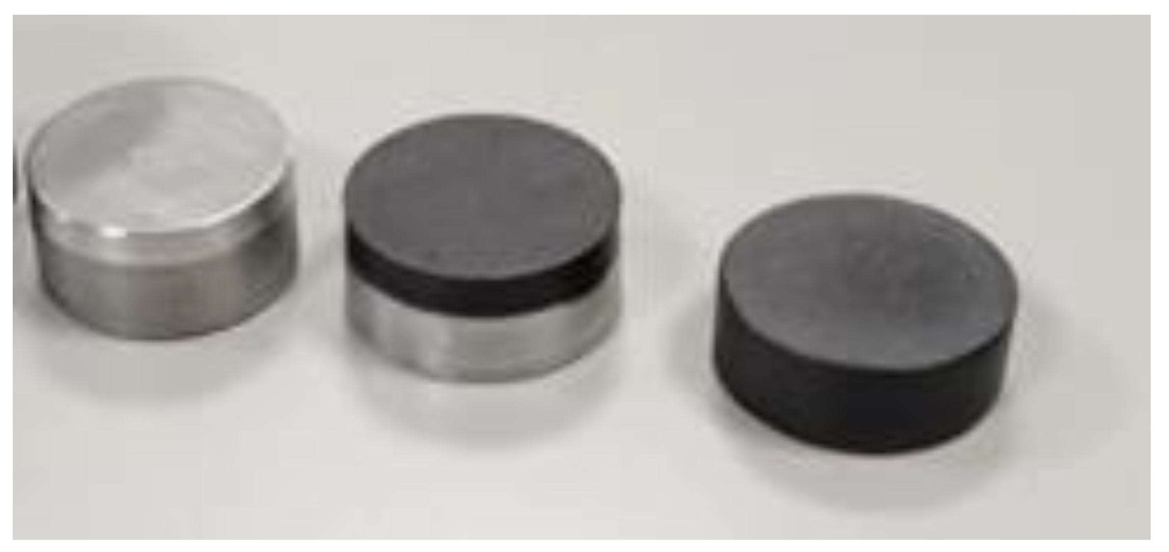
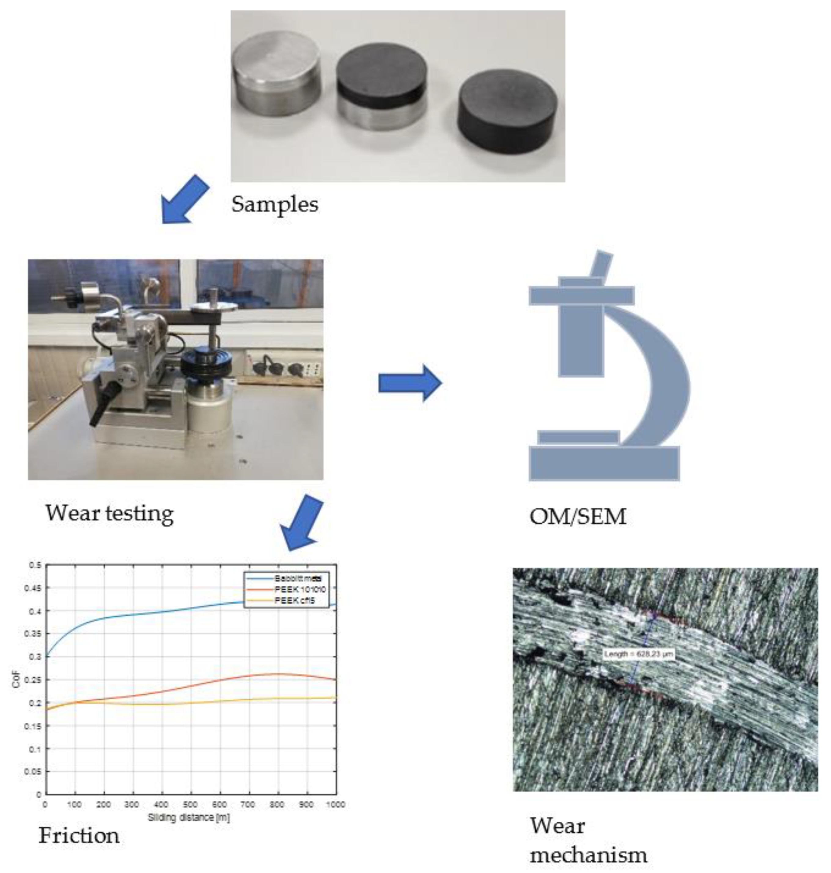
2.1. Materials Preparation and Characterization

Two different series of specimens were realized to study the tribological behavior and the bonding strength between the polymer and backing metal. For each specimen (except for those coated with Babbitt metal), the polymer studied was 3D printed using the FDM process [28].
Owing to its mechanical properties, PEEK polymers (Table 1) have lower Hertzian pressures than Babbitt metals, given an equal applied load.
The first type of specimen has a simple cylindrical shape, 30 mm in diameter and 15 mm of height (see Figure 1). Three different materials, namely Babbitt metal; PEEK with 15% carbon fiber (PEEK cf15); and PEEK with 10% carbon fiber, 10% PTFE, and 10% graphite (PEEK 101010), were analyzed to compare their tribological characteristics described in Section 2.3. The polymer coatings chosen for experimentation were chosen for a good tradeoff between performance and material/manufacturing cost as bearing coatings.
The second type of specimen has the shape according to ISO 4386-2, (see Figure 2) and was used to test the bond strength. The samples were manufactured through a mechanical bonding between a metal support body and a polymer coating (FDM) of 3 mm thickness. The backing metal support has, in turn, two different shapes, named “male interlocking” and “female interlocking”, as shown in Figure 3.
Finally, four different types of backing metals were used for the support body: 39CrNi, brass, aluminum, and AISI 304. Two types of polymer were used for the coating, i.e., PEEK cf15 and PEEK 101010.
Table 2 summarizes the different types of specimens.

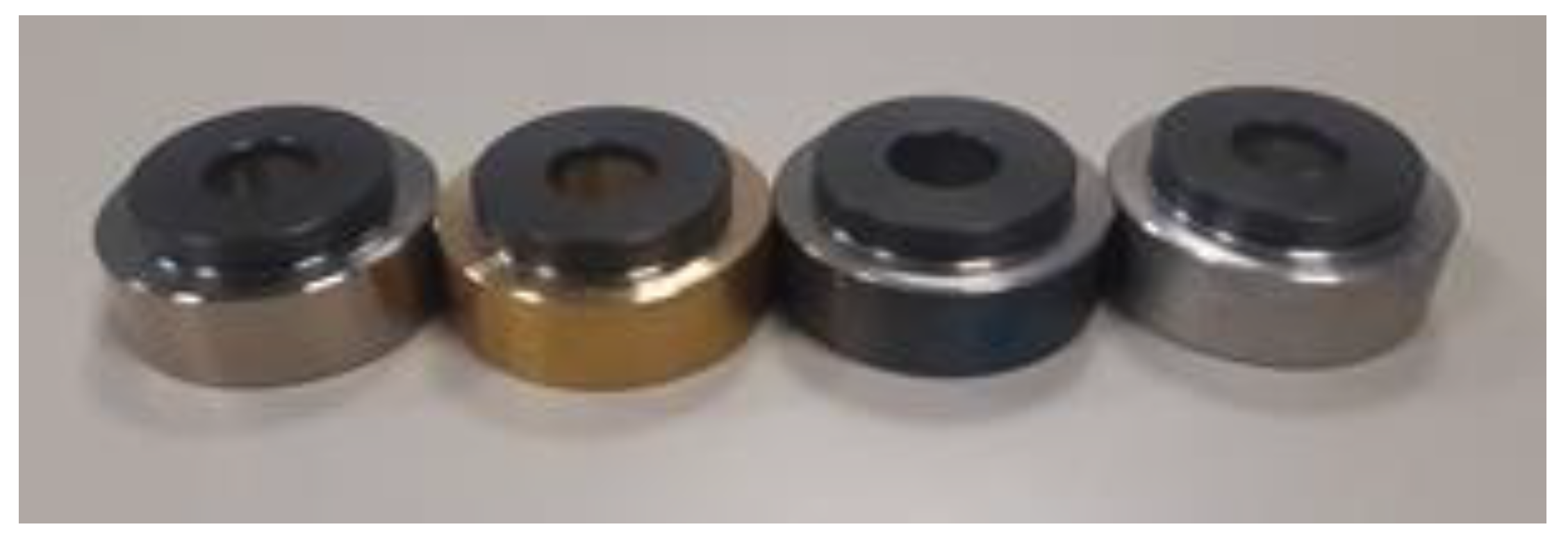
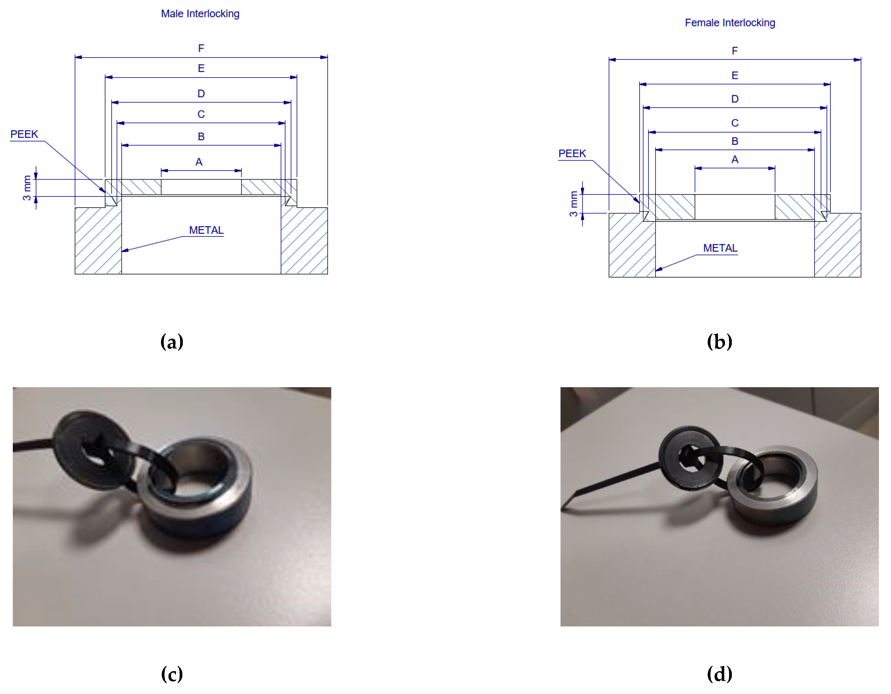
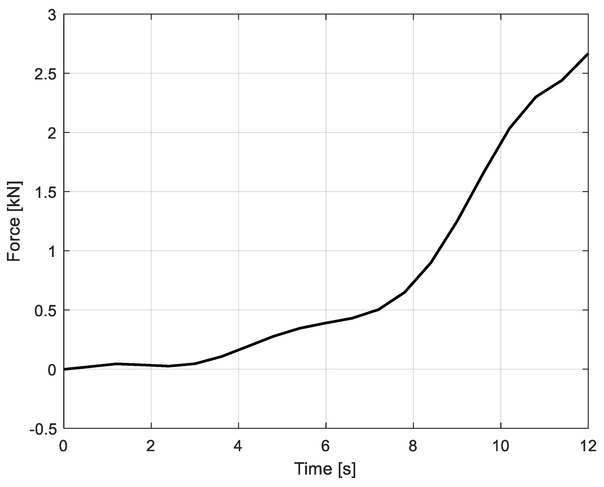
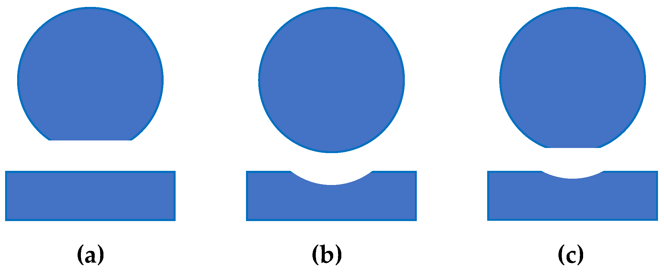
2.2. Bond Strength Tests

The suitability of the technique, proposed in this paper for bearing pad manufacturing, was tested to verify the strength of the bonding between the metal support and the PEEK polymer 3D printed on it with FDM. The Chalmers test (according to ISO 4386-2) was used as shown in Figure 4. The Chalmers test is an international standard (ISO 4386-2) for destructive bond testing for bearing layers. It consists of a tensile test in which the machine acts vertically to the surface of the bond and the force is steadily increased until the specimen fractures. In Figure 4, the tensile force is plotted as a function of time and the specimen had a cross-sectional area of about 81 mm2. The results cannot be compared with those found in the literature due to the difference in the bonding method and the geometry of the interlocking with the backing metal. Table 3 summarizes the results obtained from samples that were tested by varying two geometries, two PEEK materials, and four different backing materials.
Data show that the specimens with PEEK cf15 performed better than those using PEEK 101010, while an influence of the specimen geometry can also be observed. In fact, the female configuration leads to higer values in the test, while the male configuration gives lower resistance values, due to the more favorable configuration for detachment phenomena.
Moreover, the results of specimens with PEEK 101010 and brass and aluminum as backing material are much lower compared with PEEK cf15 samples.
Considering only the backing parts, just the 39CrNi reached acceptable value. Only 39CrNi backing parts with PEEK cf15 coating were tested in the female configuration, which reached the highest bonding value.

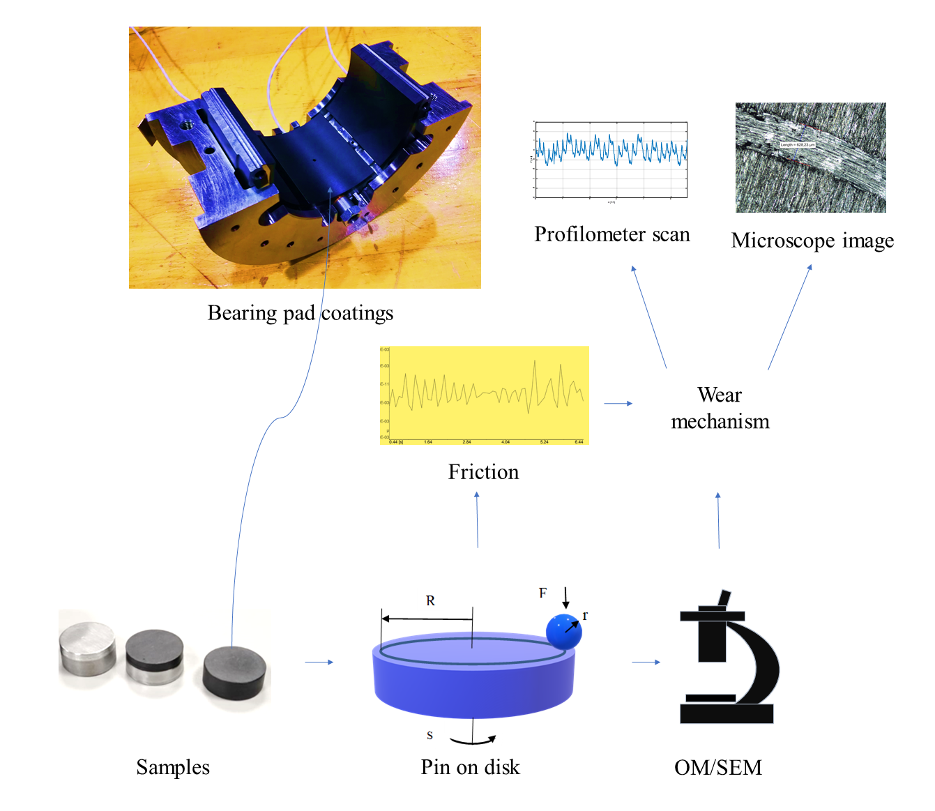
2.3. Tribological Tests

A CSM Instruments tribometer (CSM, Swiss)(schematic rappresentation of the machine is shown in Figure 5) was employed for the friction and wear tests based on ASTM G99-17 and DIN 50324, where a 6.00 mm diameter 100Cr6 ball, under normal loads of 1 and 5 N, was rubbed against the first type of specimens in Section 3.1 at 25 °C temperature and 50% humidity.
Tribometer parameters were set and run with a number of sequences of 3 in alternating mode for different wear radii. Graphs of CoF curves versus sliding distance were obtained from TriboX software version 4.1.I (CSM, Swiss), installed in the tribometer to analyze the frictional behavior of the specimens.
Before each test, the ball and the disk were ultrasonically cleaned in ethanol for 5 min. Table 4 shows the experimental parameters that were applied while the tests were run for a minimum of three repetitions for the same load. Good repeatability was obtained, with a maximum difference of ±5% in both CoF mean value and wear rate.
Sketches of the experimental setups are shown in Figure 6.

3. Results and Discussion

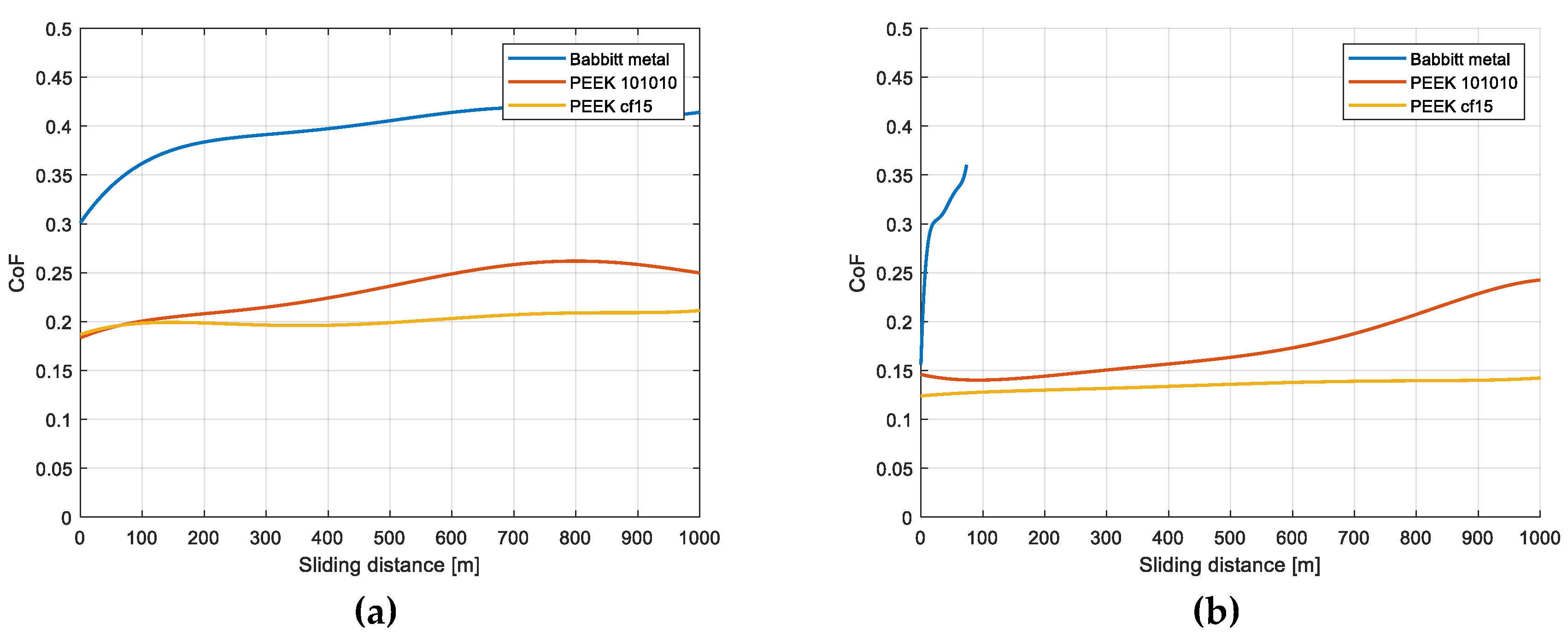
3.1. Friction Coefficient Evaluation

During BOD tests, three possible situations may happen, as shown in Figure 7. The situation of Figure 7c, with loads of 1 and 5 N, occurs only for the Babbitt disk samples.
In the case of all the PEEK samples, only disc wear is detected (see Figure 7b), likely due to the low Hertzian pressure. Using the mechanical properties given in Table 1 for the Babbitt samples, the Hertzian pressure ranges between 0.38 and 0.65 GPa, while for the PEEK-based polymers the pressure is about 0.12–0.21 GPa. The lower Hertzian pressure allows for increased load and/or rotational speed to meet increasingly challenging requirements for bearings, such as continuous improvement of efficiencies and size reduction (downsizing and light design).
The CoF of the specimens shows specific behavior for different creep lengths for loads of 1 and 5 N. By analyzing the values obtained for CoF, two stages with different behavior were identified (see Figure 8).
The first phase is observed up to 200 m of runway length, where stick-slip phenomena occur. This effect develops in the dynamic contact between the two surfaces, resulting in unstable movements along the runway. In the first instant of friction, as shown in the graph, a considerable increase in contact force and CoF was caused by the detachment of initial asperities from the surface material of the tribological coupling. These asperities can cause specific roughness values, leading to a smaller contact surface area between the ball and the disk, resulting in higher contact pressures.
The action of the high contact pressures on the rough surfaces tends to remove the soft asperities, promoting the detachment of wear debris on the track, and resulting in high amplitude in CoF values and the effects of abrasive wear mechanisms.
The increase in CoF values is mainly caused by the movement of the ball on the initial wear debris of the PEEK/Babbitt asperities, probably resulting in local temperature increase in the contact zone. During the 5 N load test (see Figure 8) of the Babbitt sample, a combination of friction and temperature conditions also promotes adhesive phenomena from the disk particles to the ball surface.
To reduce the impact of the first step on the calculation of the average CoF value, the CoF after 200 m of sliding length was calculated. The average CoF values obtained for Babbitt metal, PEEK 101010, and PEEK cf15 at 1 N load applied are, respectively: 0.41 ± 0.02, 0.25 ± 0.01, and 0.20 ± 0.01, while at 5 N load applied, the values are, respectively: 0.31 ± 0.02, 0.17 ± 0.01, and 0.14 ± 0.01 (Figure 8).
The next phase begins with a decrease in CoF values and a stabilization of the CoF profile. An important reduction in the amplitude of CoF oscillations is also visible. This behavior is mainly due to a growth of the disk wear track adhesion layer formed by the slip track above the pin in the layered sections.
Under these conditions, the adhesion phenomena and the formation of wear debris result in a sliding process in which surfaces of the same material contact each other.
Babbitt metal has a higher average CoF value than the PEEK-based polymers and the curve is “thicker”, i.e., has more fluctuation, implying that some wear phenomena are occurring due to the high Hertzian pressure and temperature in the contact zone.
While for the PEEK 101010 sample the CoF is not constant in the last phase of the test, the PEEK cf15 shows a lower average CoF value, which is also generally constant during all the phases of the test.
When the applied load is 5 N, the Babbitt metal has a higher average CoF value than the PEEK-based polymers. Moreover, in this load condition, the test for the Babbitt coating failed due to the high tangential forces and was stopped after approximately 100 m of sliding distance; the presence of debris was massive, coming from both the disk and the ball.
The PEEK 101010 has a lower average CoF value than the Babbitt metal, but at the end of the test, the trend is not constant and seems to increase. The PEEK cf15 has a behavior that can be described as good: a low friction value during the test and constant trend. Wear occurs in the disc specimens only for PEEK.

3.2. Optical Microscopy and Wear Calculation

The disc track widths were measured (see Figure 9) using optical microscope images (see Figure 10) and disk volume losses were calculated according to ASTM G99-17, using the simplified formula:
  d = π w t 3 6 s
where d is disk volume loss (mm3), w is wear track radius (mm), t is track width (mm), and s is sphere radius (mm). Wear is very light with PEEK-based polymers and the wear volume loss calculated using the transverse track profile integrated on the circumference is only possible for the Babbitt coating. In this case, the valley obtained for plastic deformation is evident (see Figure 11a); the roughness is no longer comparable to the transverse track profile. In the case of tests on polymer-based coatings, the transverse profile of the track is of the same order of magnitude as the roughness measurement and the formula results are therefore not significant (see Figure 11b,c). The simplified formula used according to ASTM G99-17 gives us a ranking on the three tested bearing layers and allows us to use the same formulation for all coatings in terms of wear performance.
To determine the depth of the wear track, the surface specimens were analyzed using a profilometer scan (Perthometer PGK) (Mahr, Germany); the results are shown in Figure 11 for Babbitt metal, PEEK 101010, and PEEK cf15 coatings. Only for the Babbitt sample is the wear track depth evident, while for the PEEK specimens the depth is of the same order of magnitude as the surface roughness.

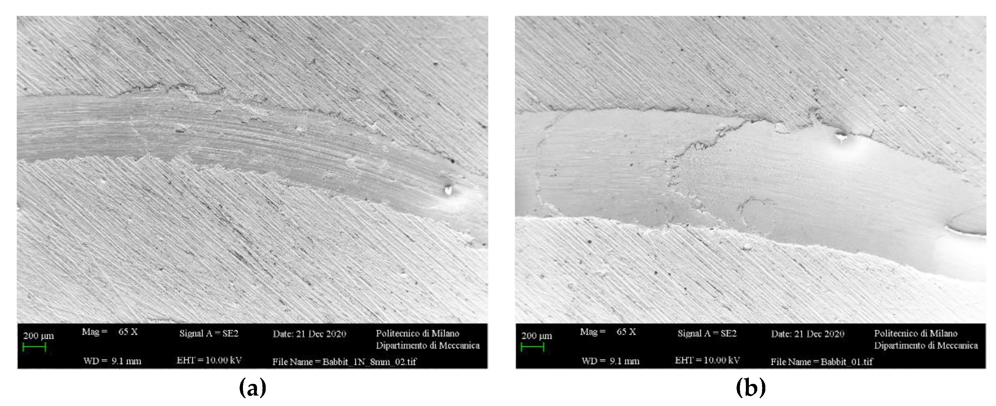
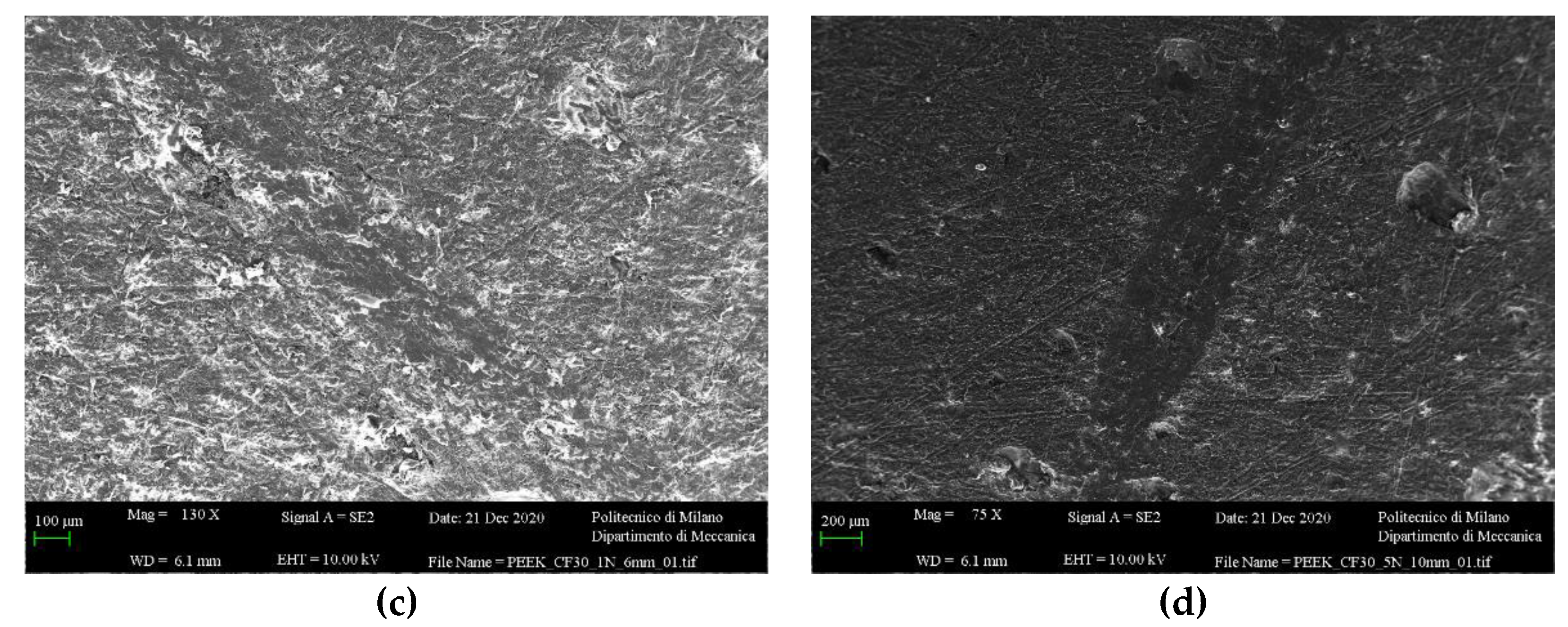
3.3. SEM Analysis of Worn Surfaces

Figure 12 shows the SEM micrographs of PEEK polymers surface and Babbitt metal after the dry sliding wear tests performed with 1 and 5 N applied load. In all the cases with 1 N of load, it is possible to observe that wear on the dry surfaces is low and there are no adhesive wear phenomena.
On the contrary, in the case of the 5 N load, the adhesive phenomenon (see Figure 12b) occurs for the Babbitt sample. The load influenced the severity and nature of wear, as already observed from the optical microscopic studies. A close-up of the SEM image (see Figure 13) clearly shows the adhesion phenomenon. The adhesive wear is due to high Hertzian pressure and to the localized increased temperature on both surfaces (ball and disk). The Babbitt surface deforms plastically due to high tangential force.
For the Babbitt layer, the wear is higher than PEEK. The Babbitt surface plastic deforms (see Figure 11a) and adhesive wear [29] occurs due to the adhesion between asperities when they touch, followed by plastic shearing of the tips of the softer asperities which then adhere to the opposing surface, and finally separate as wear debris particles.
Wear scars on the sliding surface show plastically deformed material on the edge of the track (see Figure 11a).

4. Conclusions

In the present research work, the tribological performance of different PEEK-based polymer coatings, namely PEEK 101010 and PEEK cf15, were investigated using a ball-on-disk machine in sliding mode at different loads at room temperature and compared with the Babbitt metal coating conventionally used in the bearing field. Dry condition tests were carried out to have the worst possible situation: insufficient lubrication (failure in the lubrication system) and/or startup phase.
Polymer-based coatings were analyzed for their ability to adhere to different bearing backsides considering different materials and using the ISO 4386-2 standard.
The changes in CoF with surface modification and wear mechanism were studied. The following conclusions can be drawn from the results:
  • For the dry tests with 1 N load, the average values of CoF are 0.41 ± 0.02, 0.25 ± 0.01, and 0.20 ± 0.01 for Babbitt metal, PEEK 101010, and PEEK cf15, respectively.
  • For dry tests with 5 N load, the average CoF values are 0.31 ± 0.02, 0.17 ± 0.01, and 0.14 ± 0.01 for Babbitt metal, PEEK 101010, and PEEK cf15, respectively.
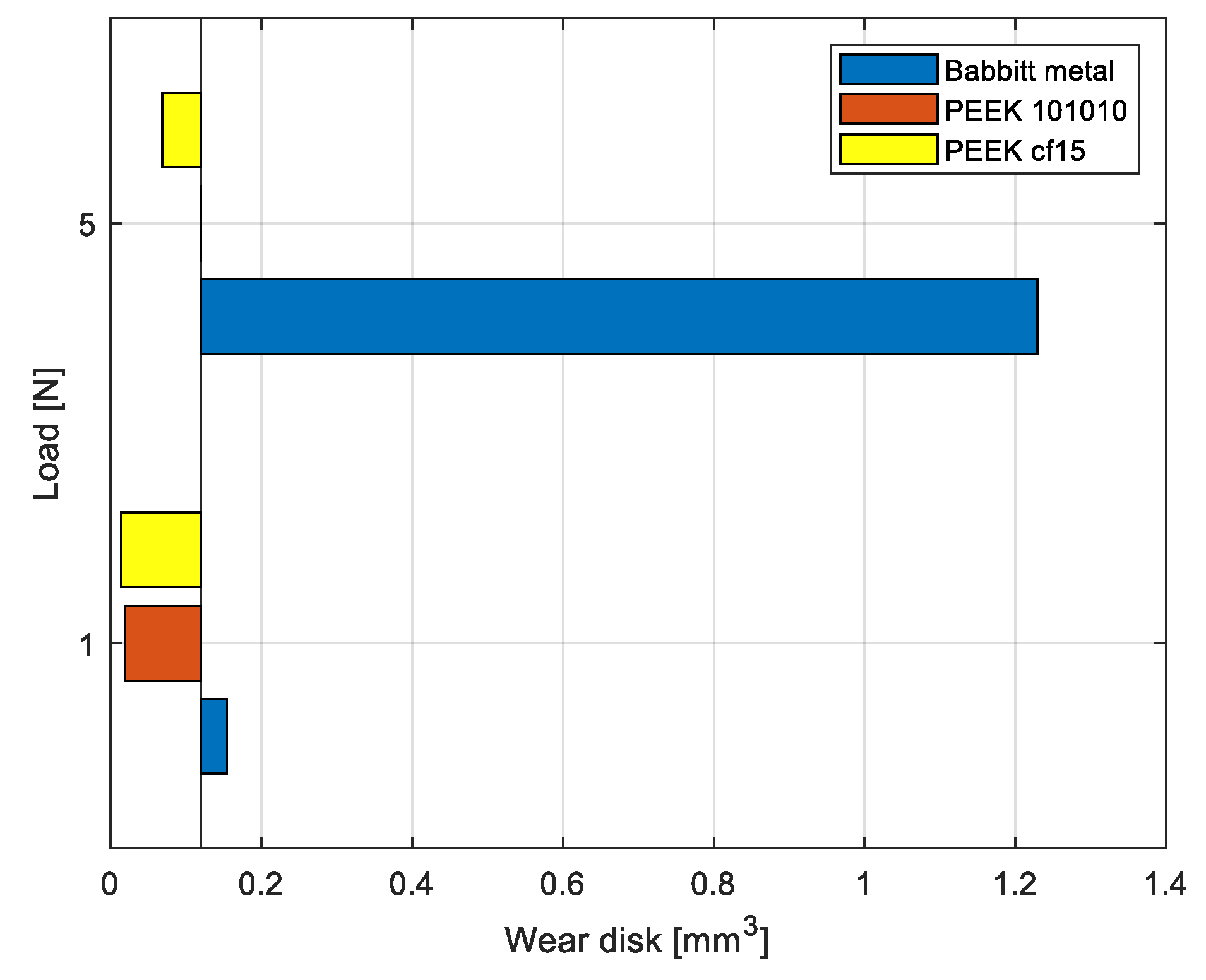
  • Wear for both PEEK-based coatings is low and about 50% lower than Babbitt metal for the 1 N dry tests. For the 5 N tests, the wear for the polymer-based coatings is one-tenth of that with the Babbitt.
  • Adhesion tests consider different geometric shapes and different combinations of backing/coating materials. Only one test was done in female configuration while the male configuration was analyzed in detail because it is subject to detachment. Considering brass and aluminum as support material, PEEK cf15 has an adhesion strength of 29 and 27 MPa, 50% higher than PEEK 101010. With 39CrNi as the backing part, PEEK cf15 has an adhesion strength of 29 MPa, 16% higher than PEEK 101010.
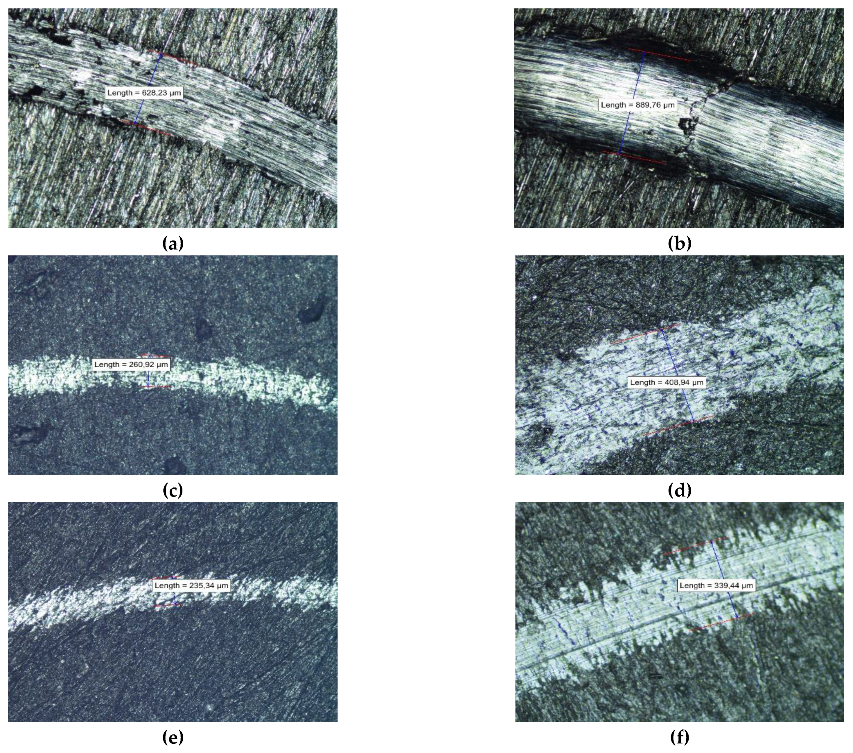
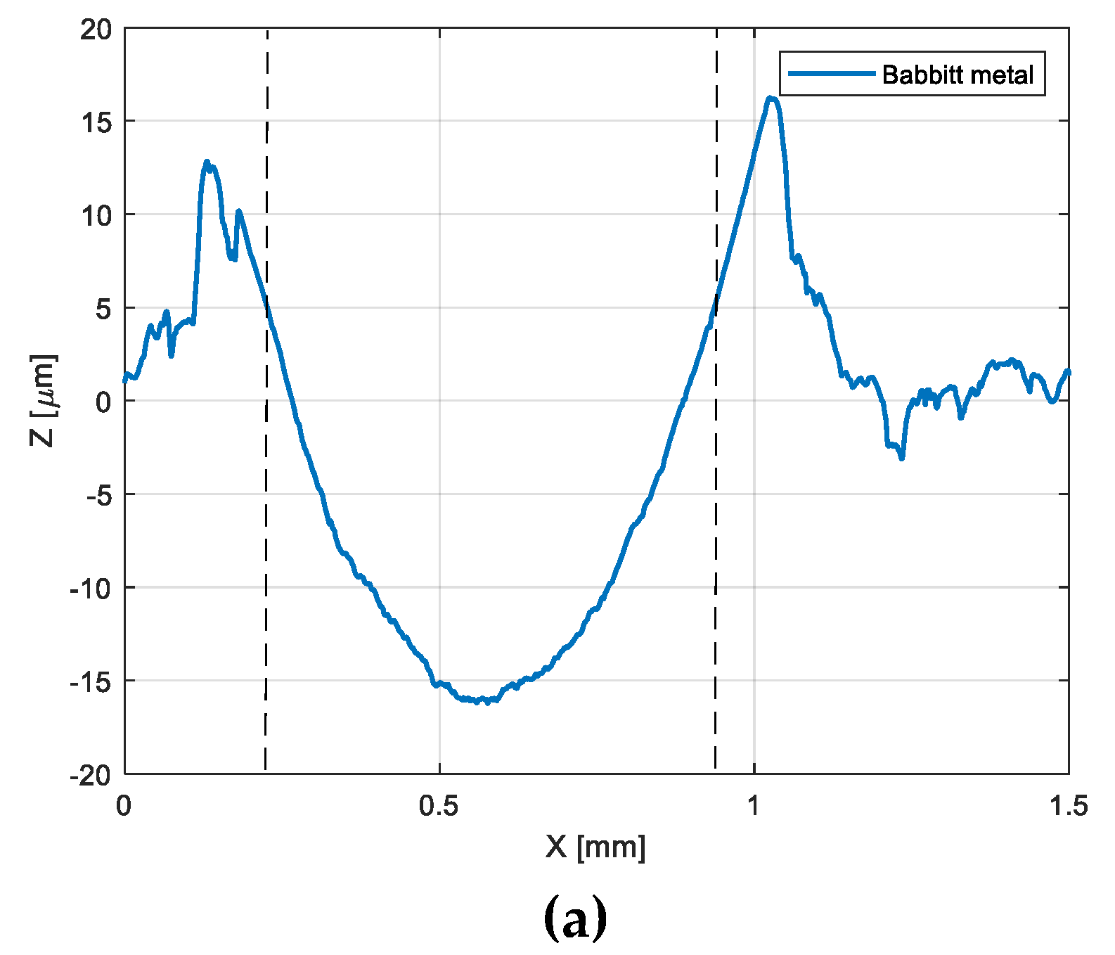
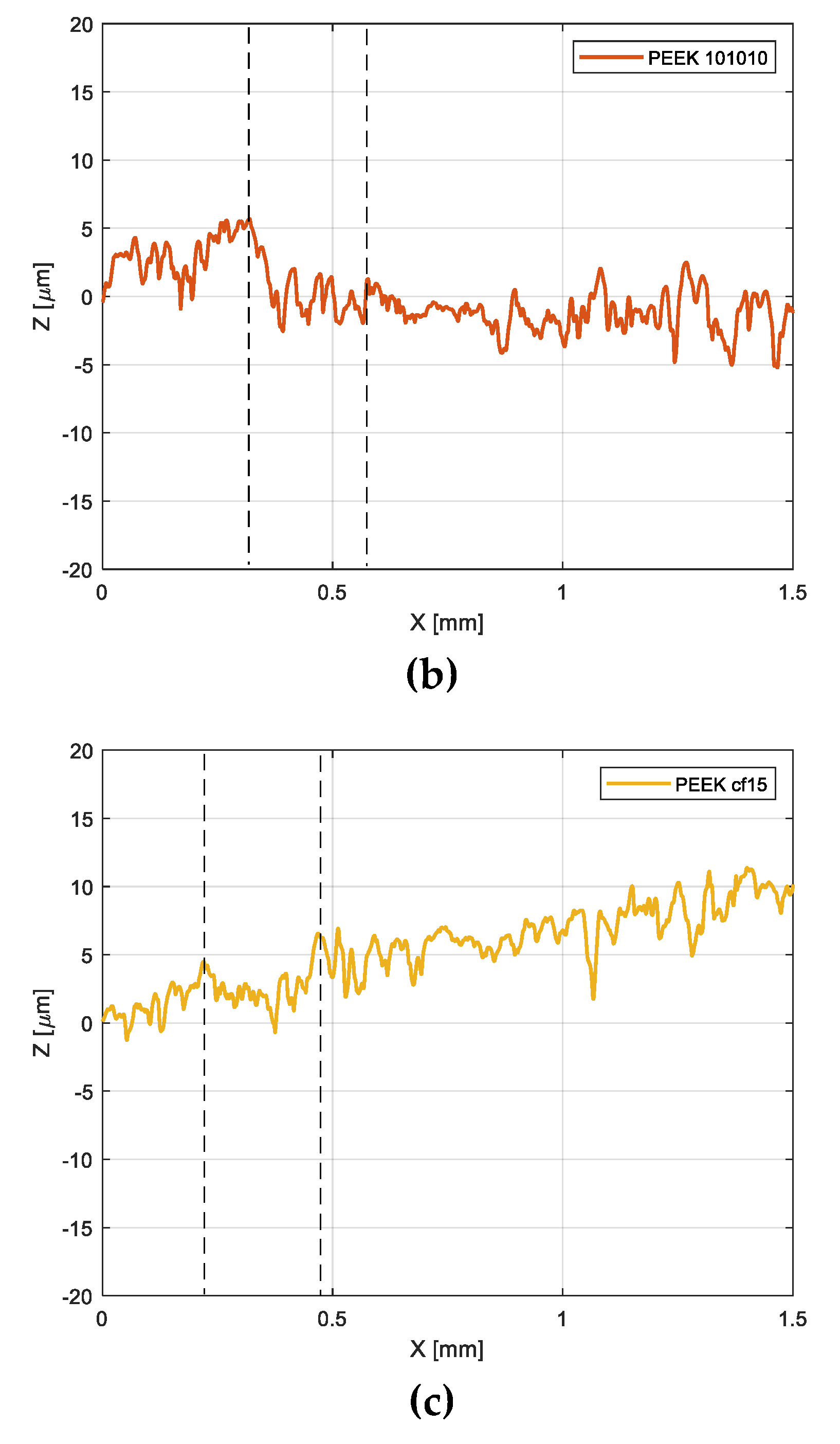
  • The adhesive wear phenomenon is only evident in the dry test with 5 N load for the Babbitt metal coating, as can be seen from the microscopic optical/electron images and profilometer scan images.

Author Contributions

D.M. performed the theoretical analysis, the computation, and the experimental tests, wrote the draft, and revised the manuscript; G.R. wrote the draft and revised the manuscript. N.L., S.C. and P.P. checked the logic described and the validity of the theory in the draft and the final version of the manuscript. All authors have read and agreed to the published version of the manuscript.

Funding

This research received no external funding.

Institutional Review Board Statement

Not applicable.

Informed Consent Statement

Not applicable.

Data Availability Statement

Data sharing not applicable. No new data were created or analyzed in this study. Data sharing is not applicable to this article.

Acknowledgments

The present work was undertaken under the support of the Italian Ministry for Education, University and Research by means of the project Department of Excellence LIS4.0 (Integrated Laboratory for Lightweight and Smart Structures).

Conflicts of Interest

The authors declare no conflict of interest.

References

  1. Keyser, P. A new look at Heron’s “Steam Engine”. Arch. Hist. Exact Sci. 1992, 44, 107–124. [Google Scholar] [CrossRef]
  2. Scaife, W. From Galaxies to Turbines: Science, Technology and the Parsons Family; CER Press: Brussels, Belgium, 1999. [Google Scholar]
  3. Pennacchi, P. Introduction of advanced technologies for steam turbine bearings. In Advances in Steam Turbines for Modern Power Plants, 1st ed.; Woodhead Publishing: Duxford, UK, 2017; pp. 321–380. [Google Scholar]
  4. Koring, R. Improved White Metal Alloys—An International Comparison, 5th ed.; ECKA Granules Germany GmbH: Velden, Germany, 2008. [Google Scholar]
  5. Fuerst, T.K.A. Behaviour of big bearings: Polymer coated bearings in comparison to Babbitt bearings. Alstom HYDRO 2005, 17–20. [Google Scholar]
  6. Glavatskih, S. Evaluating Thermal Performance of a PTFE-Faced Tilting Pad Thrust Bearing. J. Tribol. 2003, 125, 319–324. [Google Scholar] [CrossRef]
  7. Ricci, R.; Chatterton, S.; Pennacchi, P.; Vania, A. Multiphysics modeling of a tilting pad thrust bearing: Comparison between white metal and polymeric layered pads. In Proceedings of the ASME 2011 International Design Engineering Technical Conferences and Computers and Information in Engineering Conference, Washington, DC, USA, 28–31 August 2011; pp. 995–1002. [Google Scholar]
  8. Ettles, C.M.; Knox, R.T.; Ferguson, J.H.; Horner, D. Test Results for PTFE-Faced Thrust Pads, With Direct Comparison Against Babbitt-FacedPads and Correlation with Analysis. J. Tribol. 2013, 125, 814–823. [Google Scholar] [CrossRef]
  9. Glavatskih, S.B.; Fillon, M. TEHD Analysis of Thrust Bearings With PTFE-Faced Pads. J. Tribol. 2005, 128, 49–58. [Google Scholar] [CrossRef]
  10. Zhou, J.; Blair, B.; Argires, J.; Pitsch, D. Experimental Performance Study of a High Speed Oil Lubricated Polymer Thrust Bearing. Lubricants 2015, 3, 3–13. [Google Scholar] [CrossRef] [Green Version]
  11. Davim, J.P.; Cardoso, R. Tribological behaviour of the composite PEEK-CF30 at dry sliding against steel using statistical techniques. Mater. Des. 2006, 27, 338–342. [Google Scholar] [CrossRef]
  12. Soifer, A.M.; Kodnir, D.S.; Baiborodov, Y.I. An elastic sliding bearing on the basis of elastically deforming material MR in combination with fluoroplas. Izv. Vyss. Uchebn. Zaved. Mashinostr. 1966, 15, 514–517. [Google Scholar]
  13. Wodtke, M. Hydrodynamic Thrust Bearings with Polymer Lining. Tribologia 2016, 268, 225–237. [Google Scholar] [CrossRef]
  14. Hentschke, C. Interlocking metal-polymer bond by 3D-printed grid structure for hydrodynamic thrust bearings with PEEK-lined pads. In Proceedings of the 18th EDF—PPRIME Work, Palaiseau, France, 10–11 October 2019. [Google Scholar]
  15. Berchtold, O.; Pajaczkowski, P.A. Hydrodynamic Bearing Pad Construction. Patent EP 3 276 191 A1, 2018. [Google Scholar]
  16. Riboni, G. Cuscitto PEEK. Patent 102020000023422, 2020. [Google Scholar]
  17. Croccolo, D.; De Agostinis, M.; Vincenzi, N. Design of hybrid steel-composite interference fitted and adhesively bonded connections. Int. J. Adhes. Adhes. 2012, 37, 19–25. [Google Scholar] [CrossRef]
  18. Tseng, J.W.; Liu, C.Y.; Yen, Y.K.; Belkner, J.; Bremicker, T.; Liu, B.H.; Sun, T.-J.; Wang, A.B. Screw extrusion-based additive manufacturing of PEEK. Mater. Des. 2018, 140, 209–221. [Google Scholar] [CrossRef]
  19. Feuerbach, T.; Thommes, M. Design and Characterization of a Screw Extrusion Hot-End for Fused Deposition Modeling. Molecules 2021, 26, 590. [Google Scholar] [CrossRef] [PubMed]
  20. Kurtz, S.M.; Nevelos, J. PEEK bearing materials for total joint replacement. In PEEK Biomaterials Handbook; William Andrew: Norwich, NY, USA, 2019; pp. 403–418. [Google Scholar]
  21. Brockett, C.L.; Carbone, S.; Fisher, J.; Jennings, L.M. PEEK and CFR-PEEK as alternative bearing materials to UHMWPE in a fixed bearing total knee replacement: An experimental wear study. Wear 2017, 374, 86–91. [Google Scholar] [CrossRef] [PubMed]
  22. Yao, C.; Qi, Z.; Chen, W.; Zhang, C. Effect of CF/PEEK plasticity behavior on the mechanical performance of interference-fit joint. Polym. Compos. 2021, 42, 2574–2588. [Google Scholar] [CrossRef]
  23. Zhu, J.; Xie, F.; Dwyer-Joyce, R.S. PEEK composites as self-lubricating bush materials for articulating revolute pin joints. Polymers 2020, 12, 665. [Google Scholar] [CrossRef] [PubMed] [Green Version]
  24. Sumer, M.; Unal, H.; Mimaroglu, A. Evaluation of tribological behaviour of PEEK and glass fibre reinforced PEEK composite under dry sliding and water lubricated conditions. Wear 2008, 265, 1061–1065. [Google Scholar] [CrossRef]
  25. Theiler, G. PTFE- and PEEK-Matrix Composites for Tribological Applications at Cryogenic Temperatures and in Hydrogen. Doctoral Dissertation, Technischen Universität Berlin, Berlin, Germany, 2005. [Google Scholar]
  26. Aly, A.A. Heat treatment of polymers: A review. Int. J. Mater. Chem. Phys. 2015, 1, 132–140. [Google Scholar]
  27. Dickens, P.M. PEEK as a Bearing Material. In Advances in Manufacturing Technology; McGoldrick, P.F., Ed.; Springer: Boston, MA, USA, 1986. [Google Scholar]
  28. Deng, X.; Zeng, Z.; Peng, B.; Yan, S.; Ke, W. Mechanical properties optimization of poly-ether-ether-ketone via fused deposition modeling. Materials 2018, 11, 216. [Google Scholar] [CrossRef] [PubMed] [Green Version]
  29. Jiménez, A.-E.; Bermúdez, M.-D. 2-Friction and wear. In Tribology for Engineers; Woodhead Publishing: Sawston, UK, 2011; pp. 33–63. [Google Scholar]
Figure 1. Samples for tribological characterization of the coating (from left to right: Babbitt metal, PEEK 101010, and PEEK cf15).
Lubricants 09 00112 g001
Figure 2. Samples with different backing metal (from left to right: 39CrNi, brass, aluminum, and AISI 304) with PEEK coating and geometry according to ISO 4386-2.
Lubricants 09 00112 g002
Figure 3. Male and female interlocking for the specimens: (a,b) drawings, (c,d) samples.
Lubricants 09 00112 g003
Figure 4. Sample of Chalmers bonding test.
Lubricants 09 00112 g004
Figure 5. Typical ball-on-disk setup where r is the ball diameter, R is the radius of the wear track, s is the rotational speed of the disk, and F is the normal force applied on the ball.
Lubricants 09 00112 g005
Figure 6. Flowchart of the experimental tests.
Lubricants 09 00112 g006
Figure 7. Three possible situations for different wear resistance of ball and flat disk specimens: (a) only the ball wears, (b) only the disk wears, and (c) both ball and disk wear.
Lubricants 09 00112 g007
Figure 8. Dry test CoF curves using the BOD tribometer for different coating materials (Babbitt metal, PEEK 101010, PEEK cf15) at (a) 1 N load and at (b) 5 N load.
Lubricants 09 00112 g008
Figure 9. Disk volume loss calculated according to ASTMG99-17.
Lubricants 09 00112 g009
Figure 10. Optical microscope image of the disk wear under the load of 1 N (left) and 5 N (right); (a,b) the first row is for Babbitt sample, (c,d) second for PEEK 101010, and (e,f) last row for PEEK cf15.
Lubricants 09 00112 g010
Figure 11. Profilometer scan after 5 N load test for the material specimens; from the top: (a) Babbitt metal, (b) PEEK 101010, and (c) PEEK cf15.
Lubricants 09 00112 g011aLubricants 09 00112 g011b
Figure 12. SEM image of the wear track at room temperature at 1 N (left) and 5 N (right). The material (a,b) on the top is Babbitt; (c,d) PEEK 101010 is on the bottom.
Lubricants 09 00112 g012aLubricants 09 00112 g012b
Figure 13. SEM image of the wear track of the 5 N Babbitt test and zoom of adhesive wear phenomenon on the right.
Lubricants 09 00112 g013
Table 1. Mechanical properties of Babbitt metal and PEEK polymers.
Babbitt MetalPEEK Polymers
Young’s modulus(N/mm2)57,0007800
Poisson’s ratio(-)0.350.42
Thermal conductivity(W/m K)450.66
Table 2. Summary of the different types of specimens.
Characteristic TestedCoating Material TestedSample Geometry
Tribological
  • PEEK reinforced with 15% carbon fiber (PEEK cf15)
  • PEEK with 10% carbon fiber, 10% PTFE 10%, and graphite (PEEK 101010)
  • White Metal
Cylindrical
Bond strength
  • PEEK reinforced with 15% carbon fiber (PEEK cf15)
  • PEEK with 10% carbon fiber, 10% PTFE 10%, and graphite (PEEK 101010)
ISO 4386-2
Table 3. Results of the Chalmers bonding test.
Sample #Interlocking ShapeBackingCoatingAreaMax. ForceBond Strength Rch.
(-)(-)(-)(-)(mm2)(N)(MPa)
1MALE39CrNiPEEK CF1581233329
2MALEBrassPEEK CF1581253429
3MALEAluminumPEEK CF1581237327
4MALEAISI 304PEEK CF1581244630
5MALE39CrNiPEEK 10101081205825
6MALEBrassPEEK 1010108188511
7MALEAluminumPEEK 1010108195412
8FEMALE39CrNiPEEK CF1579427654
Table 4. Ball-on-disk (BOD) testing parameters.
BOD Parameters
ParametersUnitsValue
Radius track(mm)4–10
Linear speed(m/s)0.3
Normal load(N)1–5
Stop condition (sliding length)(m)1000
Temperature(°C)25
Humidity(%)50
Acquisition rate(Hz)10
Ball materials(-)100Cr6
Publisher’s Note: MDPI stays neutral with regard to jurisdictional claims in published maps and institutional affiliations.

