
Stable Characteristics Optimization of Anti-Symmetric Cylindrical Shell with Laminated Carbon Fiber Composite

 ,
,
Abstract
:1. Introduction
2. Anti-Symmetric Cylindrical Shell
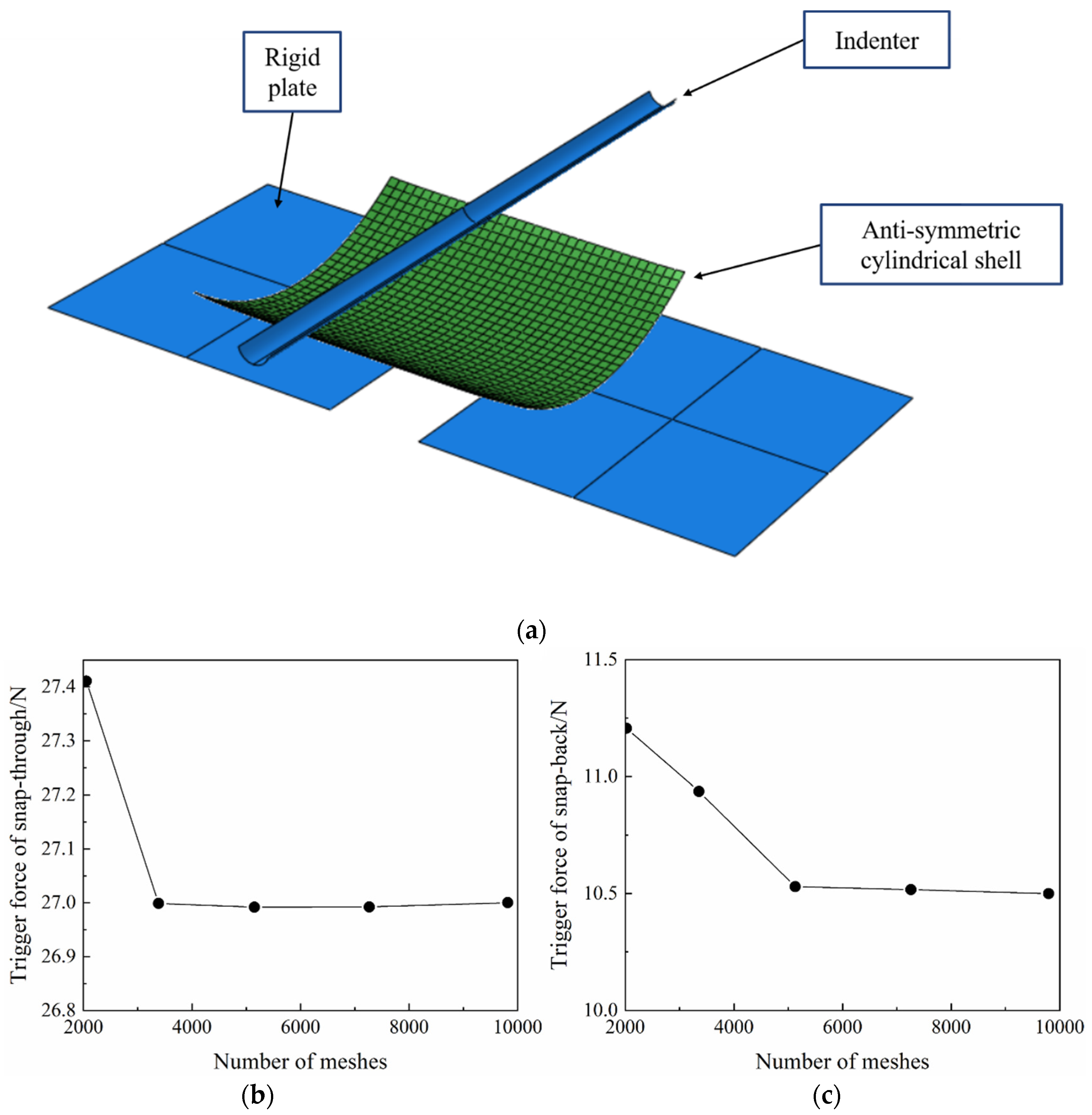
2.1. Finite Element Model
2.2. Problem Description
2.3. Design Variable
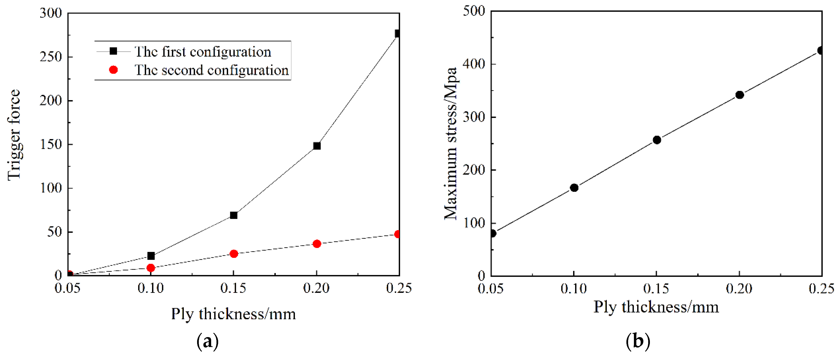
2.3.1. The Layer Thickness t
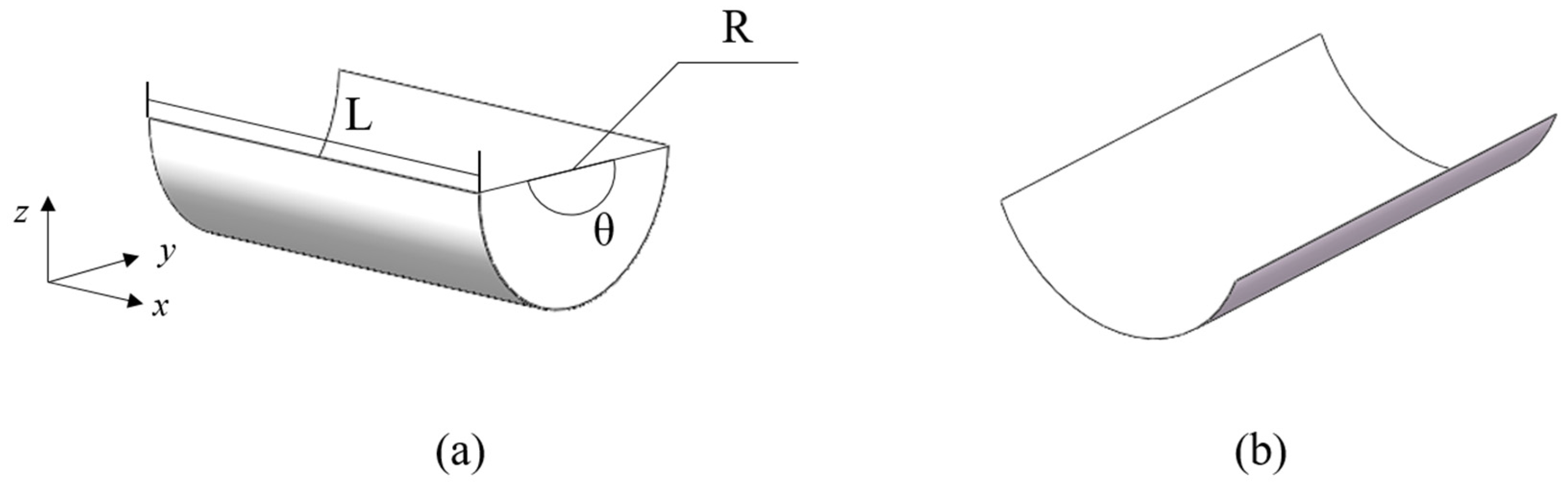
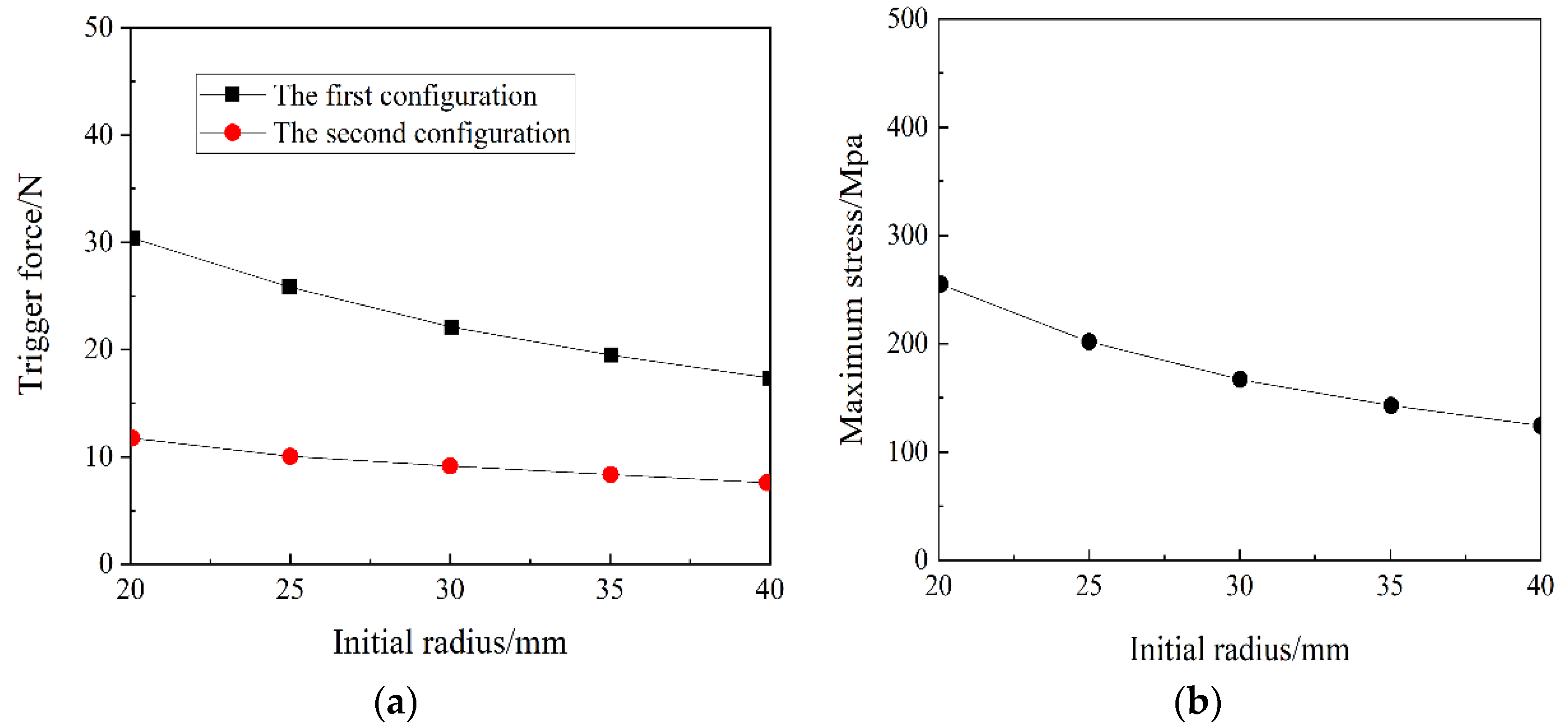
2.3.2. The Initial Natural Radius R
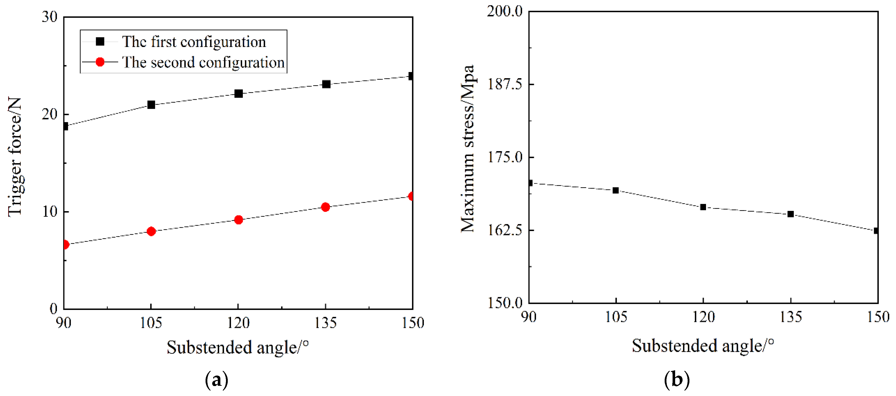
2.3.3. The Central Angle θ
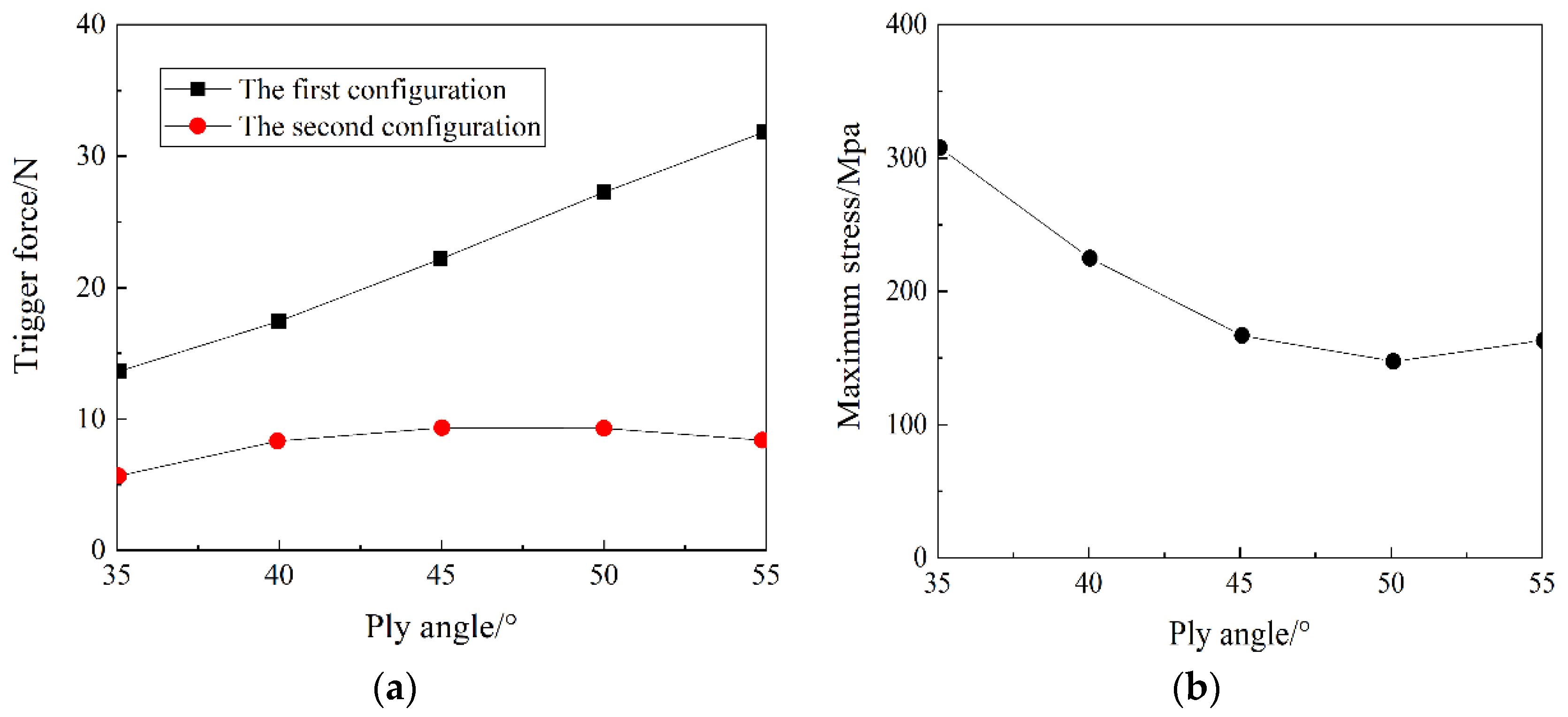
2.3.4. The Layer Angle α
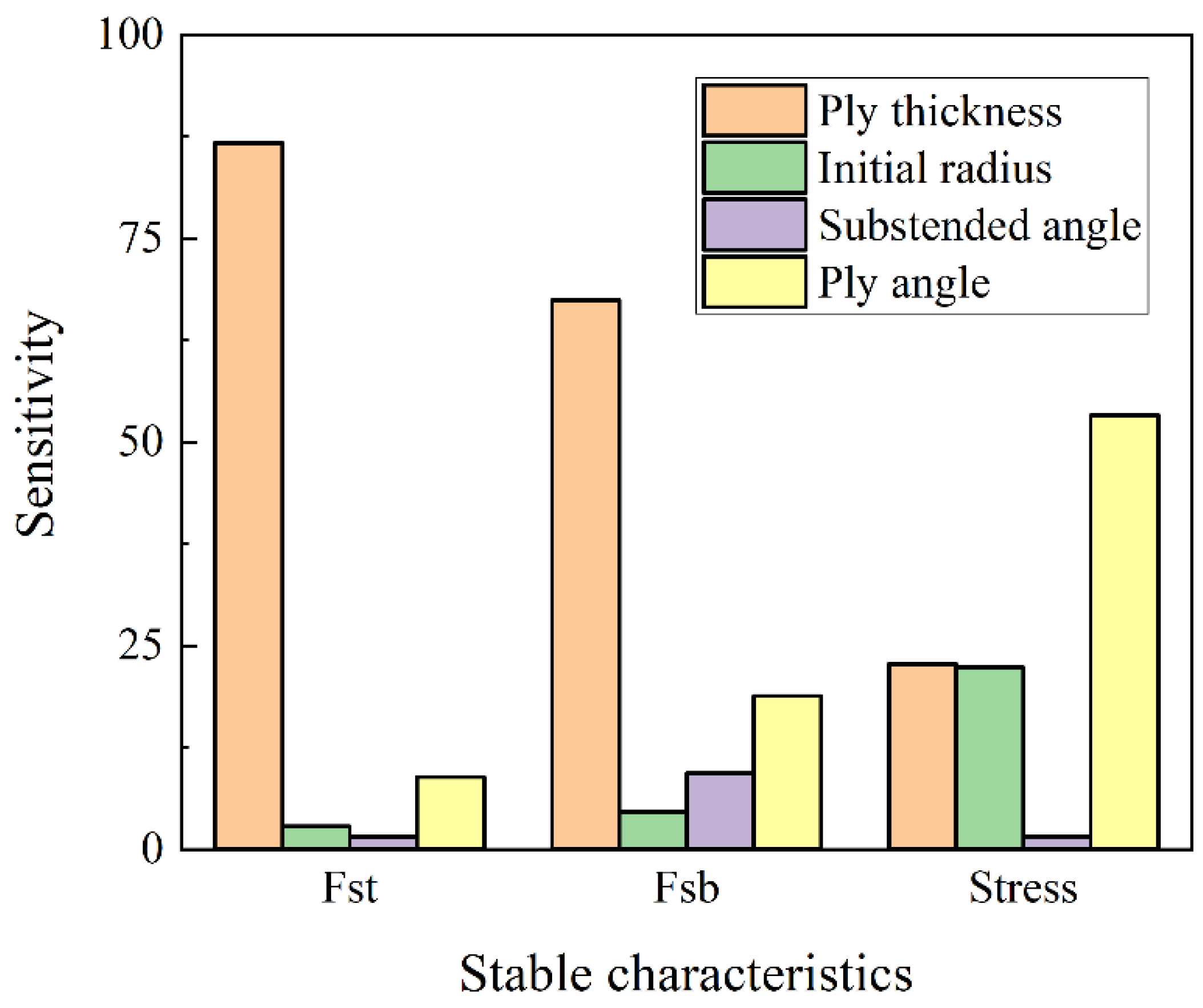
2.3.5. Analysis of the Influence Level of Design Variables
3. Multi-Objective Optimization Model Based on NSGA-Ⅱ Algorithm
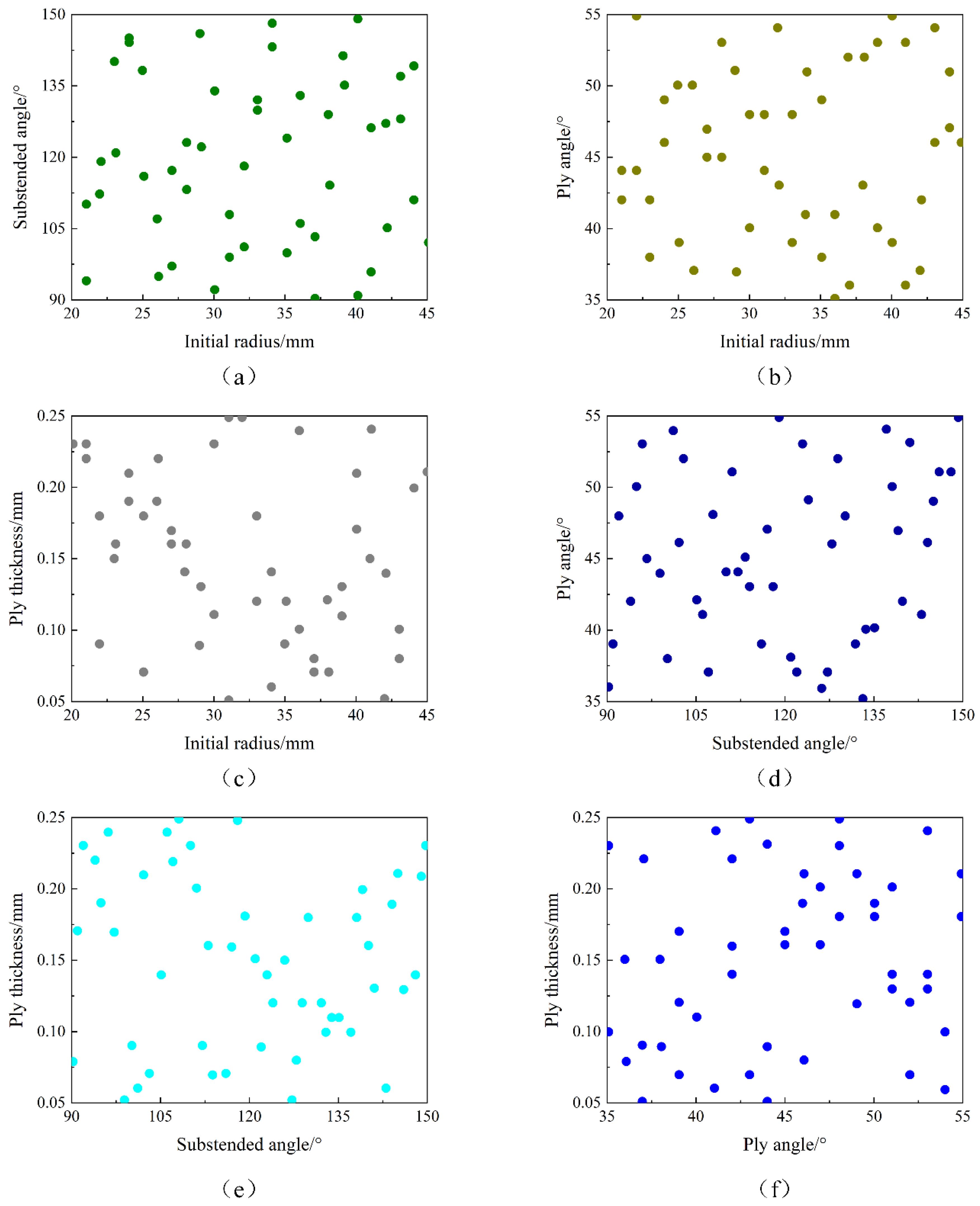
3.1. Specimen Point Collection
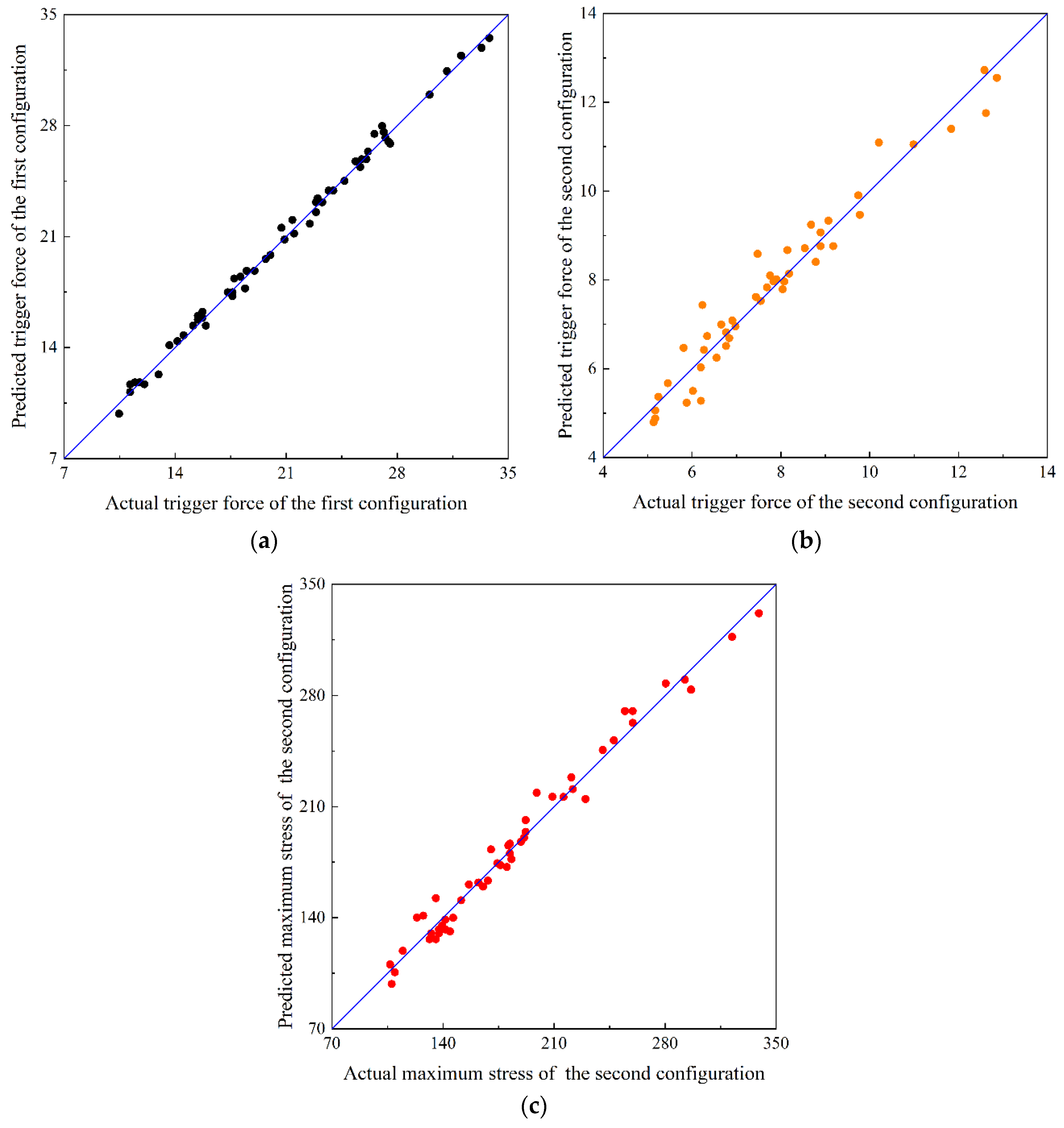
3.2. Approximate Model
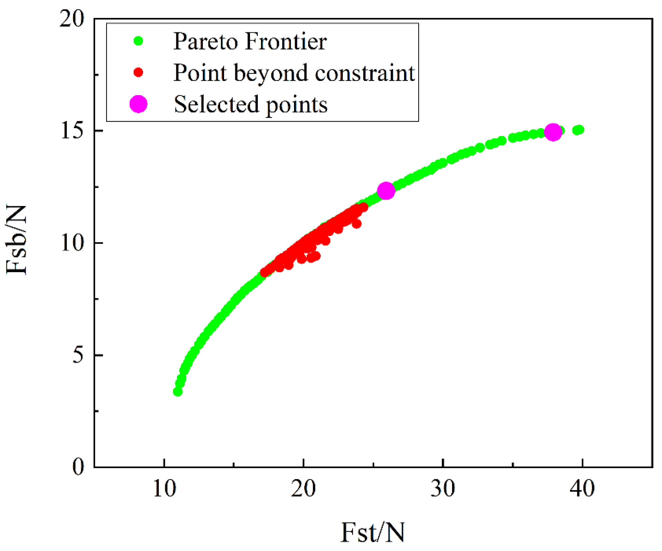
3.3. Optimization Results
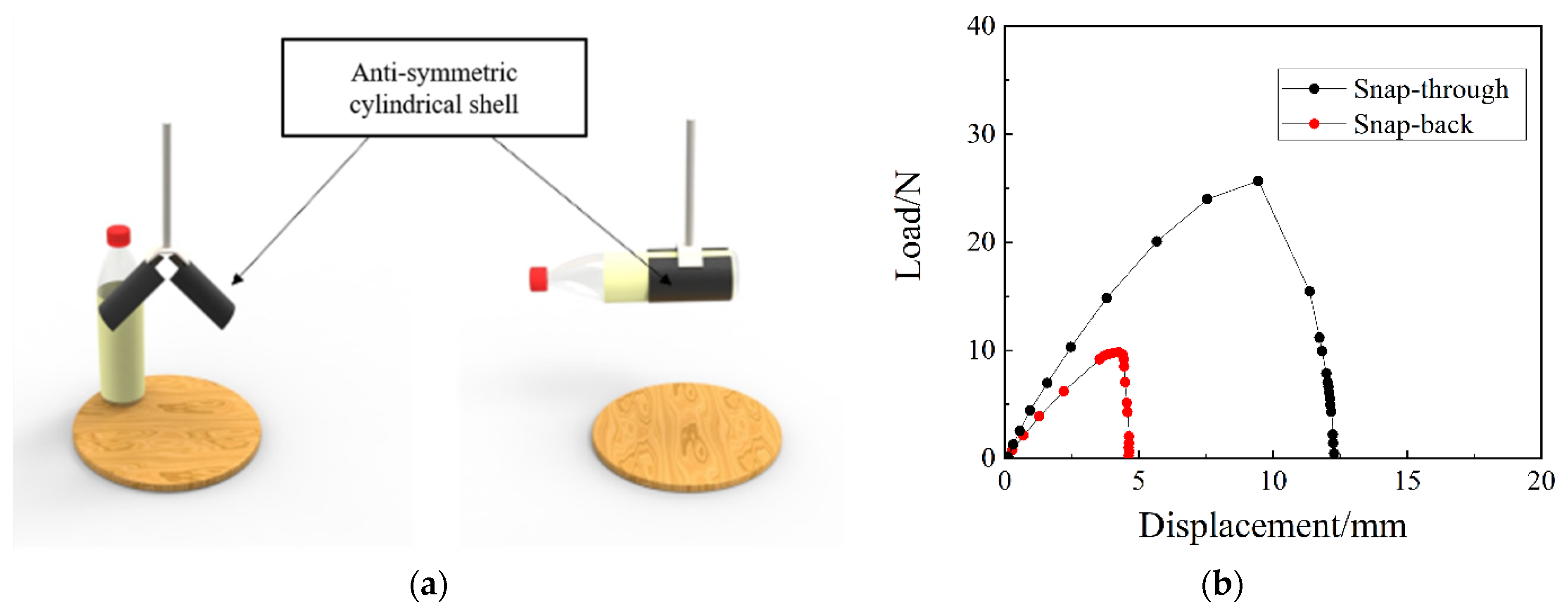
4. Experimental Verification
5. Conclusions
Author Contributions
Funding
Institutional Review Board Statement
Informed Consent Statement
Data Availability Statement
Acknowledgments
Conflicts of Interest
References
- Zhang, Z.; Pei, K.; Sun, M.; Wu, H.; Yu, X.; Wu, H.; Jiang, S.; Zhang, F. A novel solar tracking model integrated with bistable composite structures and bimetallic strips. Compos. Struct. 2020, 248, 112506. [Google Scholar] [CrossRef]
- Zhang, Z.; Li, Y.; Yu, X.; Li, X.; Wu, H.; Wu, H.; Jiang, S.; Chai, G. Bistable morphing composite structures: A review. Thin-Walled Struct. 2019, 142, 74–97. [Google Scholar] [CrossRef]
- Li, S.; Qin, J.; Li, C.; Feng, Y.; Zhao, X.; Hu, Y. Optimization and compressive behavior of composite 2-D lattice structure. Mech. Adv. Mater. Struct. 2018, 27, 1213–1222. [Google Scholar] [CrossRef]
- Nicassio, F. Shape prediction of bistable plates based on Timoshenko and Ashwell theories. Compos. Struct. 2021, 265, 113645. [Google Scholar] [CrossRef]
- Hibbert, L.T.; Jordaan, H.W. Considerations in the design and deployment of flexible booms for a solar sail. Adv. Space Res. 2020, 67, 2716–2726. [Google Scholar] [CrossRef]
- Li, Y.; Zhang, Z.; Yu, X.C.; Chai, H.; Lu, C.; Wu, H.; Wu, H.; Jiang, S. Tristable behaviour of cross-shaped unsymmetric fibre-reinforced laminates with concave-convex boundaries. Eng. Struct. 2020, 225, 111253. [Google Scholar] [CrossRef]
- Zhang, Z.; Li, Y.; Wu, H.L.; Zhang, H.; Wu, H.; Jiang, S.; Chai, G. Mechanical analysis of functionally graded graphene oxide-reinforced composite beams based on the first-order shear deformation theory. Mech. Adv. Mater. Struct. 2020, 27, 3–11. [Google Scholar] [CrossRef]
- Sun, M.; Xiong, L.B.; Zhang, Z.; Zhang, H.; Chai, H.; Zhang, F.; Wu, H.; Jiang, S. Systematic analysis of a new novel variable stiffness stable composite structures using theory, FEM and experiment. Mech. Adv. Mater. Struct. 2021, 1–10. [Google Scholar] [CrossRef]
- Zhang, Z.; Pei, K.; Sun, M.; Wu, H.; Wu, H.; Jiang, S.; Zhang, F. Tessellated multistable structures integrated with new transition elements and anti-symmetric laminates. Thin-Walled Struct. 2022, 170, 108560. [Google Scholar] [CrossRef]
- Hufenbach, W.; Gude, M.; Kroll, L.; Sokolowski, A.; Werdermann, B. Adjustment of residual stresses in unsymmetric fiber-reinforced composites using genetic algorithms. Mech. Compos. Mater. 2001, 37, 71–78. [Google Scholar] [CrossRef]
- Betts, D.N.; Kim, H.A.; Bowen, C.R. Optimization of stiffness characteristics for the design of bistable composite laminates. AIAA J. 2012, 50, 2211–2218. [Google Scholar] [CrossRef]
- Panesar, A.S.; Weaver, P.M.J.C.S. Optimisation of blended bistable laminates for a morphing flap. Compos. Struct. 2012, 94, 3092–3105. [Google Scholar] [CrossRef]
- Kuder, I.K.; Arrieta, A.F.; Ermanni, P. Design space of embeddable variable stiffness bi-stable elements for morphing applications. Compos. Struct. 2015, 122, 445–455. [Google Scholar] [CrossRef]
- Haldar, A.; Jansen, E.; Hofmeister, B.; Bruns, M.; Rolfes, R. Analysis of novel morphing trailing edge flap actuated by multistable laminates. AIAA J. 2020, 58, 3149–3158. [Google Scholar] [CrossRef]
- Zhang, Z.; Ma, W.L.; Wu, H.L.; Wu, H.; Jiang, S.; Chai, G. A rigid thick miura-ori structure driven by bistable carbon fibre-reinforced polymer cylindrical shell. Compos. Sci. Technol. 2018, 167, 411–420. [Google Scholar] [CrossRef]
- Zhang, Z.; Chen, D.D.; Wu, H.L.; Bao, Y.; Chai, G. Non-contact magnetic driving bioinspired Venus flytrap robot based on bistable anti-symmetric CFRP structure. Compos. Struct. 2016, 135, 17–22. [Google Scholar] [CrossRef] [Green Version]
- Zhang, Z.; Chen, B.B.; Lu, C.D.; Wu, H.; Wu, H.; Jiang, S.; Chai, G. A novel thermo-mechanical anti-icing/de-icing system using bi-stable laminate composite structures with superhydrophobic surface. Compos. Struct. 2017, 180, 933–943. [Google Scholar] [CrossRef] [Green Version]
- Belbachir, N.; Draich, K.; Bousahla, A.A. Bending analysis of anti-symmetric cross-ply laminated plates under nonlinear thermal and mechanical loadings. Steel Compos. Struct. 2019, 33, 81–92. [Google Scholar]
- Santo, L.; Bellisario, D.; Iorio, L.; Quadrini, F. Shape memory composite structures for self-deployable solar sails. Astrodynamics 2019, 3, 247–255. [Google Scholar] [CrossRef]
- Viswanathan, K.; Javed, S. Free vibration of anti-symmetric angle-ply cylindrical shell walls using first-order shear deformation theory. J. Vib. Control 2016, 22, 1757–1768. [Google Scholar] [CrossRef]
- Baharali, A.A.; Yazdi, A.A. Analytical approach to study the vibration of delaminated multi-scale composite cylindrical shells. Polym. Compos. 2021, 42, 153–172. [Google Scholar] [CrossRef]
- Narwariya, M.; Choudhury, A. Parametric study on Harmonic Analysis of anti-symmetric laminated composite Plate. Mater. Today Proc. 2018, 5, 232–238. [Google Scholar] [CrossRef]
- Narwariya, M.; Sharma, A.K.; Patidar, V.; Chauhan, P.S. Harmonic Analysis of symmetric and anti-symmetric laminated skew plate using finite element method. IOP Conf. Ser. Mater. Sci. Eng. 2019, 691, 012007. [Google Scholar] [CrossRef]
- Garg, N.; Karkhanis, R.S.; Sahoo, R.; Maiti, P.R.; Singh, B.N. Trigonometric zigzag theory for static analysis of laminated composite and sandwich plates under hygro-thermo-mechanical loading. Compos. Struct. 2018, 209, 460–471. [Google Scholar] [CrossRef]
- Barroso, E.S.; Parente, E.; De Melo, A.M.C. A hybrid PSO-GA algorithm for optimization of laminated composites. Struct. Multidiscip. Optim. 2017, 55, 2111–2130. [Google Scholar] [CrossRef]
- Coelho, P.G.; Guedes, J.M.; Rodrigues, H.C. Multiscale topology optimization of bi-material laminated composite structures. Compos. Struct. 2015, 132, 495–505. [Google Scholar] [CrossRef]
- Reddy, M.P.; Mukherjee, S.; Ganguli, R. Optimal design of damage tolerant composite using ply angle dispersion and enhanced bat algorithm. Neural Comput. Appl. 2020, 32, 3387–3406. [Google Scholar] [CrossRef]
- Aydin, L.; Aydin, O.; Artem, H.S.; Mert, A. Design of dimensionally stable composites using efficient global optimization method. J. Mater. Des. Appl. 2016, 233, 156–168. [Google Scholar] [CrossRef]
- Zhang, Z.; Pei, K.; Wu, H.L.; Sun, M.; Chai, H.; Wu, H.; Jiang, S. Bistable characteristics of hybrid composite laminates embedded with bimetallic strips. Compos. Sci. Technol. 2021, 212, 108880. [Google Scholar] [CrossRef]
- Zhang, Z.; Zhou, Y.S.; Shen, H.C.; Sun, M.; Chai, H.; Wu, H.; Jiang, S. Experimental study of orthogonal bistable laminated composite shell driven by magnetorheological elastomer. Compos. Struct. 2021, 271, 114119. [Google Scholar] [CrossRef]
- Zhang, Z.; Liao, C.J.; Chai, H.; Ni, X.; Pei, K.; Sun, M.; Wu, H.; Jiang, S. Multi-objective optimization of controllable configurations for bistable laminates using NSGA-Ⅱ. Compos. Struct. 2021, 226, 113764. [Google Scholar]
- Zhang, Z.; Ni, X.Q.; Wu, H.L.; Sun, M.; Bao, G.; Wu, H.; Jiang, S. Pneumatically actuated soft gipper with bistable structures. Soft Robot. 2021. [Google Scholar] [CrossRef]
- Rezaiee-Pajand, M.; Arabi, E.; Masoodi, A.R. Nonlinear analysis of FG-sandwich plates and shells. Aerosp. Sci. Technol. 2019, 87, 178–189. [Google Scholar] [CrossRef]
- Rezaiee-Pajand, M.; Masoodi, A.R.; Arabi, E. Geometrically nonlinear analysis of FG doubly-curved and hyperbolical shells via laminated by new element. Steel Compos. Struct. 2018, 28, 389–401. [Google Scholar]
- Brunetti, M.; Vincenti, A.; Vidoli, S. A class of morphing shell structures satisfying clamped boundary conditions. Int. J. Solids Struct. 2016, 82, 47–55. [Google Scholar] [CrossRef]
- Ni, X.Q.; Liao, C.J.; Li, Y.; Zhang, Z.; Sun, M.; Chai, H.; Wu, H.; Jiang, S. Experimental study of multi-stable morphing structures actuated by pneumatic actuation. Int. J. Adv. Manuf. Technol. 2020, 108, 1203–1216. [Google Scholar] [CrossRef]
- Zhang, Z.; Ni, X.Q.; Gao, W.L.; Shen, H.; Sun, M.; Guo, G.; Wu, H.; Jiang, S. Pneumatically controlled reconfigurable bistable bionic flower for robotic gripper. Soft Robot. 2021. [Google Scholar] [CrossRef]
- Bessa, M.A.; Pellegrino, S. Design of ultra-thin shell structures in the stochastic post-buckling range using Bayesian machine learning and optimization. Int. J. Solids Struct. 2018, 139–140, 174–188. [Google Scholar] [CrossRef]
- Li, X.H.; Zhang, Z.; Sun, M.; Wu, H.; Zhou, Y.; Wu, H.; Jiang, S. A magneto-active soft gripper with adaptive and controllable motion. Smart Mater. Struct. 2021, 30, 015024. [Google Scholar] [CrossRef]
- Yang, H.; Guo, H.; Liu, R.; Wang, S.; Liu, Y. Coiling and deploying dynamic optimization of a C-cross section thin-walled composite deployable boom. Struct. Multidiscip. Optim. 2020, 61, 1731–1738. [Google Scholar] [CrossRef]
- Wang, J.; Nartey, M.A.; Luo, Y.; Wang, H.; Scarpa, F.; Peng, H.-X. Designing multi-stable structures with enhanced designability and deformability by introducing transition elements. Compos. Struct. 2020, 233, 111580. [Google Scholar] [CrossRef]
- Gao, D.W.; Liang, H.T.; Shi, G.J.; Cao, L. Multiobjective optimization of carbon fiber-reinforced plastic composite bumper based on adaptive genetic algorithm. Math. Probl. Eng. 2019, 2019, 1–12. [Google Scholar]
- Wu, C.; Viquerat, A. Natural frequency optimization of braided bistable carbon/epoxy tubes: Analysis of braid angles and stacking sequences. Compos. Struct. 2017, 159, 528–537. [Google Scholar] [CrossRef] [Green Version]
- Badallo, P.; Trias, D.; Marin, L.; Mayugo, J.A. A comparative study of genetic algorithms for the multi-objective optimization of composite stringers under compression loads. Compos. Part B Eng. 2013, 47, 130–136. [Google Scholar] [CrossRef] [Green Version]
- Wang, Q.; Jia, X.L. Multi-objective optimization of CFRP drilling parameters with a hybrid method integrating the ANN, NSGA-II and fuzzy C-means. Compos. Struct. 2020, 235, 197–207. [Google Scholar] [CrossRef]
- Talebitooti, R.; Gohari, H.D.; Zarastvand, M.R. Multi objective optimization of sound transmission across laminated composite cylindrical shell lined with porous core investigating Non-dominated Sorting Genetic Algorithm. Aerosp. Sci. Technol. 2017, 69, 269–280. [Google Scholar] [CrossRef]
- Belardi, V.G.; Fanelli, P.; Vivio, F. Structural analysis and optimization of anisogrid composite lattice cylindrical shells. Compos. Part B Eng. 2018, 139, 203–215. [Google Scholar] [CrossRef]
- Yang, H.; Liu, R.Q.; Wang, Y.; Deng, Z.; Guo, H. Experiment and multiobjective optimization design of tape-spring hinges. Struct. Multidiscip. Optim. 2015, 51, 1373–1384. [Google Scholar] [CrossRef]


| Properties | Values | Units |
|---|---|---|
| Longitudinal Young’s modulus (E11) | 130 | GPa |
| Transverse Young’s modulus (E22) | 10 | GPa |
| Poisson’s ratio (μ) | 0.3 | |
| Shear modulus (G12) | 4.4 | GPa |
| Longitudinal thermal expansion coefficient (α11) | −0.018 | 10–6/°C |
| Transverse thermal expansion coefficient (α22) | 30 | 10–6/°C |
| Indicators (Standard Values) | Fst | Fsb | Smax |
|---|---|---|---|
| R2 (>0.9) | 0.9962 | 0.9571 | 0.9760 |
| RMSE (<0.2) | 0.0130 | 0.0434 | 0.0297 |
| (<0.2) | 0.0101 | 0.0329 | 0.0215 |
| (<0.3) | 0.0519 | 0.1247 | 0.1313 |
| Parameters | θ (°) | R (mm) | γ (°) | t (mm) |
|---|---|---|---|---|
| Initial specimen | 45 | 25 | 110 | 0.10 |
| Specimen 1 | 45.7 | 20 | 149.9 | 0.10 |
| Specimen 2 | 40.8 | 25 | 120 | 0.10 |
| Parameters | Finite Element Solution | Response Surface Solution | Relative Error | ||||||
|---|---|---|---|---|---|---|---|---|---|
| Fst (N) | Fsb (N) | S (MPa) | Fst (N) | Fsb (N) | S (MPa) | Fst (%) | Fsb (%) | S (%) | |
| Initial specimen | 27.0 | 10.5 | 212.1 | 25.8 | 9.8 | 201.8 | 4.8 | 7.1 | 5.1 |
| Specimen 1 | 33.8 | 14.9 | 235.9 | 34.9 | 14.9 | 241.5 | 3.2 | 0.5 | 2.3 |
| Specimen 2 | 23.3 | 12.3 | 246.6 | 22.9 | 11.2 | 250.6 | 2.1 | 9.0 | 1.6 |
| Parameters | Fst | Fsb |
|---|---|---|
| Specimen 1 | 25.14% | 42.34% |
| Specimen 2 | −13.52% | 16.72% |
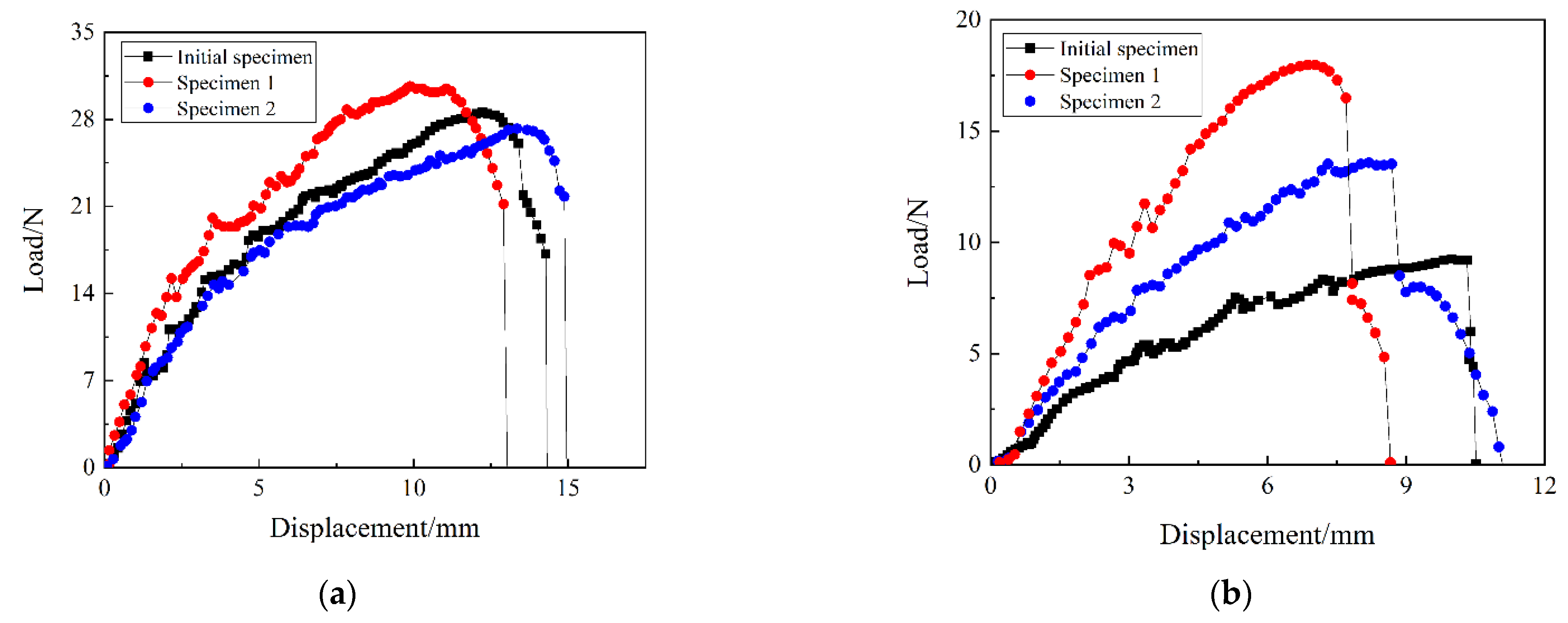
| Exp (N) | FE (N) | Relative Error (%) | ||
|---|---|---|---|---|
| Transition load in Snap-through | Initial specimen | 28.6 | 27.0 | 5.59 |
| Specimen 1 | 30.0 | 34.9 | 12.67 | |
| Specimen 2 | 27.0 | 22.9 | 13.71 | |
| Transition load in Snap-back | Initial specimen | 9.3 | 10.5 | 12.90 |
| Specimen 1 | 18 | 14.9 | 17.22 | |
| Specimen 2 | 13.5 | 11.2 | 8.89 |
| Fst | Fsb | |
|---|---|---|
| Specimen 1 | 4.90% | 93.60% |
| Specimen 2 | −5.59% | 45.20% |
Publisher’s Note: MDPI stays neutral with regard to jurisdictional claims in published maps and institutional affiliations. |
© 2022 by the authors. Licensee MDPI, Basel, Switzerland. This article is an open access article distributed under the terms and conditions of the Creative Commons Attribution (CC BY) license (https://creativecommons.org/licenses/by/4.0/).
Share and Cite
Sun, M.; Zhou, H.; Liao, C.; Zhang, Z.; Zhang, G.; Jiang, S.; Zhang, F. Stable Characteristics Optimization of Anti-Symmetric Cylindrical Shell with Laminated Carbon Fiber Composite. Materials 2022, 15, 933. https://doi.org/10.3390/ma15030933
Sun M, Zhou H, Liao C, Zhang Z, Zhang G, Jiang S, Zhang F. Stable Characteristics Optimization of Anti-Symmetric Cylindrical Shell with Laminated Carbon Fiber Composite. Materials. 2022; 15(3):933. https://doi.org/10.3390/ma15030933
Chicago/Turabian StyleSun, Min, Huping Zhou, Chongjie Liao, Zheng Zhang, Guang Zhang, Shaofei Jiang, and Feng Zhang. 2022. "Stable Characteristics Optimization of Anti-Symmetric Cylindrical Shell with Laminated Carbon Fiber Composite" Materials 15, no. 3: 933. https://doi.org/10.3390/ma15030933