
Free Vibration Analysis of Spinning Sandwich Annular Plates with Functionally Graded Graphene Nanoplatelet Reinforced Porous Core


1
Key Laboratory of Structural Dynamics of Liaoning Province, School of Sciences, Northeastern University, Shenyang 110819, China
2
School of Engineering, RMIT University, P.O. Box 71, Bundoora, VIC 3083, Australia
3
Department of Kinesiology, Shenyang Sport University, Shenyang 110102, China
*
Authors to whom correspondence should be addressed.
†
These authors contributed equally to the article.
Materials 2022, 15(4), 1328; https://doi.org/10.3390/ma15041328
Submission received: 31 December 2021
/
Revised: 2 February 2022
/
Accepted: 6 February 2022
/
Published: 11 February 2022
(This article belongs to the Section Smart Materials)
Abstract
:This paper conducted the free vibration analysis of a sandwich annular thin plate with whirl motion. The upper and lower faces of the annular plate are made of uniform solid metal, while its core is porous foamed metal reinforced by graphene nanoplatelets (GPLs). Both uniform and non-uniform distributions of GPLs and porosity along the direction of plate thickness which leads to a functionally graded (FG) core are taken into account. The effective material properties including Young’s modulus, Poisson’s ratio and mass density are calculated by employing the Halpin–Tsai model and the rule of mixture, respectively. Based on the Kirchhoff plate theory, the differential equations of motion are derived by applying the Lagrange’s equation. Then, the assumed mode method is utilized to obtain free vibration behaviors of the sandwich annular plate. The finite element method is adopted to verify the present model and vibration analysis. The effects of porosity coefficient, porosity distribution, graphene nanoplatelet (GPL) distribution, graphene nanoplatelet (GPL) weight fraction, graphene nanoplatelet length-to-thickness ratio (GPL-LTR), graphene nanoplatelet length-to-width ratio (GPL-LWR), spinning speed, outer radius-to-thickness ratio and inner radius-to-thickness ratio of the plate, are examined in detail.
1. Introduction
Spinning disks are widely applied in a rotor machinery, such as aero engines, gas turbines, and so on. The thick disk is commonly adopted in the traditional rotor structures to achieve great structural stiffness and it can be considered as a rigid body in the vibration analysis. To meet the requirements of high spinning speed and light weight, however, thin disks are increasingly used in practical engineering applications. In such cases, the flexibility and the deformation of the disk can no longer be ignored. Theoretically, the thin disk can be modeled as an elastic annular thin plate, whose vibration behaviors have been extensively investigated [1,2,3,4,5].
By employing the finite element method, Pan et al. [6] studied the vibration of rotor bearing-disk system subjected to three forces. Yang et al. [7] developed a thermal stress stiffening method to investigate the vibration behavior of spinning flexible disks. Maretic et al. [8] proposed vibrations of spinning annular plate with two different materials. By adopting the experimental method, Kang et al. [9] studied the vibration characteristics of spinning disk in an air-filled enclosure. The Ritz method is used by Kang et al. [10] to study the free vibration of spinning annular plates with variable thickness. Rao et al. [11] concerned with free vibration behaviors of an annular plate resting on Winkler foundation. Based on Mindlin plate theory, Chen et al. [12] studied the high-frequency vibration performance of an annular plate. Tan et al. [13] deal with the forced and free vibration of a thin annular plate with variable stiffness. Amin et al. [14] investigated the nonlinear vibration behaviors of an FG annular plate. Wang et al. [15] studied the free vibration of an annular plate with different edges.
Due to the spinning effect, the disk is always subjected to aerodynamic loading on its faces. To enhance structural stiffness and reduce weight, a sandwich annular plate structure could be designed in which the upper and lower faces are made of uniform solid metal and the core is porous foamed metal. Because the pores can weaken the structural stiffness, some reinforcements need to be added. GPLs, owing to their superior mechanical properties, are well suited to be the reinforcements. Recently, the vibration behavior of GPL reinforced structures for better mechanical performance has been a topic of extensive research efforts [16,17,18,19,20]. Yang and Zhao et al. [21,22,23,24] carried out extensive research on the free vibration of rotor structures reinforced by GPLs. Based on the modified couple stress theory, Adab et al. [25] studied the free vibration of a spinning sandwich micro-shell. Saidi et al. [26] investigated vibrations of an FG porous GPL reinforced plate subjected to aerodynamical loading. Li et al. [27] studied nonlinear vibrations of a sandwich FG porous GPL reinforced plate resting on Winker–Pasternak elastic foundation. Zhou et al. [28] investigated vibrations of a GPL reinforced porous cylindrical panel under supersonic flow. Gao et al. [29] conducted nonlinear free vibration analysis of a porous plate reinforced with GPLs. Baghlani et al. [30] studied uncertainty propagation in free vibration of an FG porous shell with GPL reinforcement. Anamagh et al. [31] developed a spectral-Chebyshev approach to study vibrations of an FG porous plate reinforced with GPLs. Based on a trigonometric shear deformation theory, Anirudh et al. [32] discussed the vibration behavior of a GPL reinforced FG porous beam.
For a disk with high spinning speed, sandwich structure with a functionally graded graphene nanoplatelet reinforced porous core and stiff faces is an ideal option due to its light weight yet great structural stiffness. To the best of the authors’ knowledge, however, none of the existing studies, including those mentioned above, has discussed the dynamic behaviors of such a spinning disk. This paper aims to fill in this research gap by studying the free vibration of a spinning sandwich annular plate with FG-GPL reinforced porous core. Considering the whirl motion, the annular plate is modeled by the Kirchhoff plate theory. The differential equations of motion and free vibration results are obtained by employing the Lagrange’s equation and assumed mode method, respectively. A comprehensive study is proposed to examine the effects of the material and structural parameters on the natural frequencies of the spinning annular plate. The presented conclusions can effectively aid the design of spinning annular plates with GPL reinforced porous core.
2. Theoretical Formulations
2.1. Modeling
Figure 1 plots the spinning annular plate model with GPL reinforced porous core and solid faces. The inner radius and outer radius of the annular plate are Ra and Rb, respectively. The thickness of the annular plate, the core and the face are h, hc and hf, respectively. To describe the motion and deformation of the spinning annular plate, both the fixed coordinate system (O-xyz) and polar coordinate system O-rθz1 are established. The annular plate rotates at a constant speed Ω along z1-axis direction.
2.2. Material Properties
As given in Figure 2, three porosity distributions of the core are considered. Figure 2a plots the positive trigonometric porosity distribution XP, where more pores are set around the surfaces of the annular plate and less pores are in the middle plane. Based on the open-cell scheme [33], the effective material properties are
Figure 2c shows the negative trigonometric porosity distribution OP, where fewer pores are arranged around the surfaces of the annular plate and more pores are in the middle plane. The expressions of material properties are
Besides, Figure 2b shows the uniform porosity distribution UP. The material properties are obtained as
where Ec, ρc and μc are the Young’s modulus, mass density and Poisson’s ratio of the core, respectively, while Ec0, ρc0 and μc0 are the corresponding parameters of the core without pores, respectively; (ec0, ecm) are the porosity coefficient and mass density coefficient of Pattern XP, while (e*c0, e*cm) and (αc, α’c) are the corresponding parameters of Pattern OP and UP, respectively.
Due to the typical mechanical property, the mass density coefficients and porosity coefficients are related by
According to the principle of equal mass, the mass density coefficients of different porosity distribution are determined by
Based on the Halpin–Tsai model [34], Ec0 can be given by
in which EM and EGPL are Young’s modulus of the foam metal matrix and GPLs, respectively; lc, wc and tc are the length, width and thickness of GPLs, respectively.
In accordance with the rule of mixture, it can be obtained as
where ρGPL and μGPL are the mass density and Poisson’s ratio of GPLs, respectively, while theρM and μM are the corresponding parameters of the foam metal matrix, respectively.
As shown in Figure 3, three GPL distribution patterns of the core are taken into consideration. Figure 3a illustrates the positive trigonometric GPL distribution XG, where more GPLs are adding around the surfaces of the core and less GPLs are in the middle plane, while Figure 3c gives the opposite GPL distribution OG and Figure 3b indicate the uniform GPL distribution UG.
The expression VGPL of volume fraction of GPLs corresponding to the above three GPL distributions can be expressed as
in which (λ1, λ2, λ3) is the volume fraction index. They can be determined by the GPL weight fraction WGPL in the form of
Thus, the material properties of the annular plate are
where k = hc/h is the ratio of the core thickness to annular plate thickness; Ef, μf and ρf are Young’s modulus, Poisson’s ratio and mass density of the face sheet, respectively.
2.3. Energy Functions
To obtain the equation of motion of the spinning sandwich annular plate, the energy method is applied.
The displacements of the annular plate (rx, ry, rz) are
in which w is the deflection displacement.
The velocities of the annular plate are
Thus, its kinetic energy can be obtained as
Based on the Kirchhoff plate theory, the strain and displacement can be related by
According to the generalized Hooke law, one can obtain that
Due to the deformation, the potential energy of the annular plate can be derived as
Because of the rotation effect, the plane strain can be given by
where u0 is the plane displacement.
On the basis of the generalized Hooke law, the plane stress is
In terms of equilibrium condition and boundary conditions
the plane displacement u0 can be obtained as
where κ1 and κ2 are given in the Appendix A.
Due to the rotation effect, the potential energy of the annular plate is
Finally, the total potential energy of the annular plate is
2.4. Equations of Motion
The assumed modes method is employed in this paper. The displacement of the annular plate is assumed as
in which P(t) is the generalized coordinate vector in the form of
and Φ(r) is the mode function vector, expressed as
where n is the mode number.
The mode function Rn(r) can be given by
in which J1 and I1 are first kind Bessel function and the modified one, respectively; N1 and K1 are second kind Bessel function and the modified one, respectively; An, Bn, Cn, Dn and βn can be determined by the boundary conditions of the annular plate.
According to the Lagrange equation
the equations of motion of the spinning annular plate can be derived as
where M and K are given in the Appendix A.
Setting
gives the eigenvalue equation
where vector ψ is composed of unknown constants An, Bn, Cn, Dn (n = 1, …). The natural frequency ω can be obtained by solving the eigenvalue problem from Equation (35).
3. Results and Discussions
In this part, the effects of material parameters on the free vibration behaviors of the spinning annular plate with porous core reinforced by GPLs are examined in detailed. Unless otherwise stated, the structural and material parameters [34] are given in Table 1. In addition, porosity distribution pattern XP and GPL distribution pattern XG are taken as an example in the subsequent analysis.
3.1. Convergence and Comparison Study
Before parametric analysis, the convergence and comparison analysis have to be conducted first. Table 2 lists the variations of the first four natural frequencies with mode number by theoretical method (MATLAB), which shows that convergent frequencies can be obtained at n = 6.
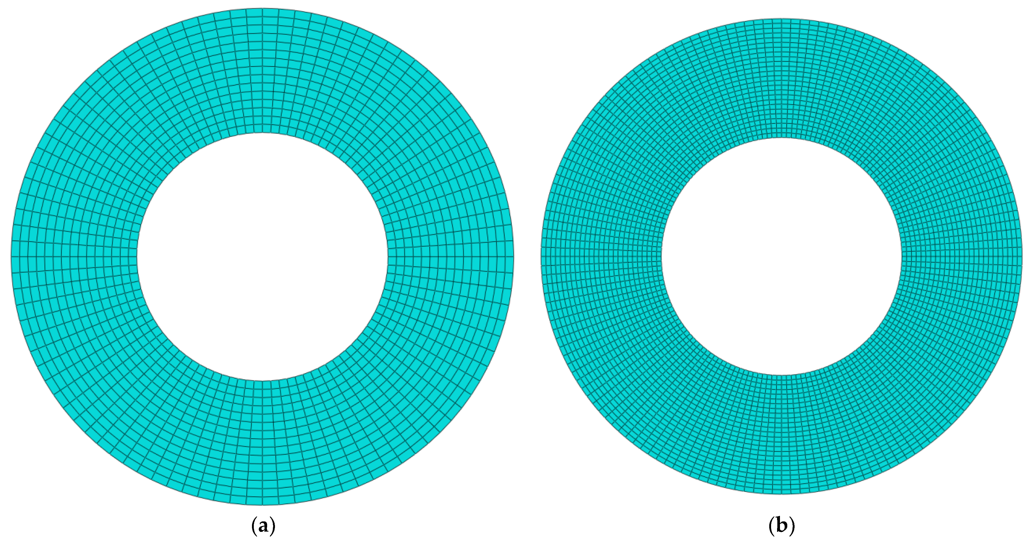
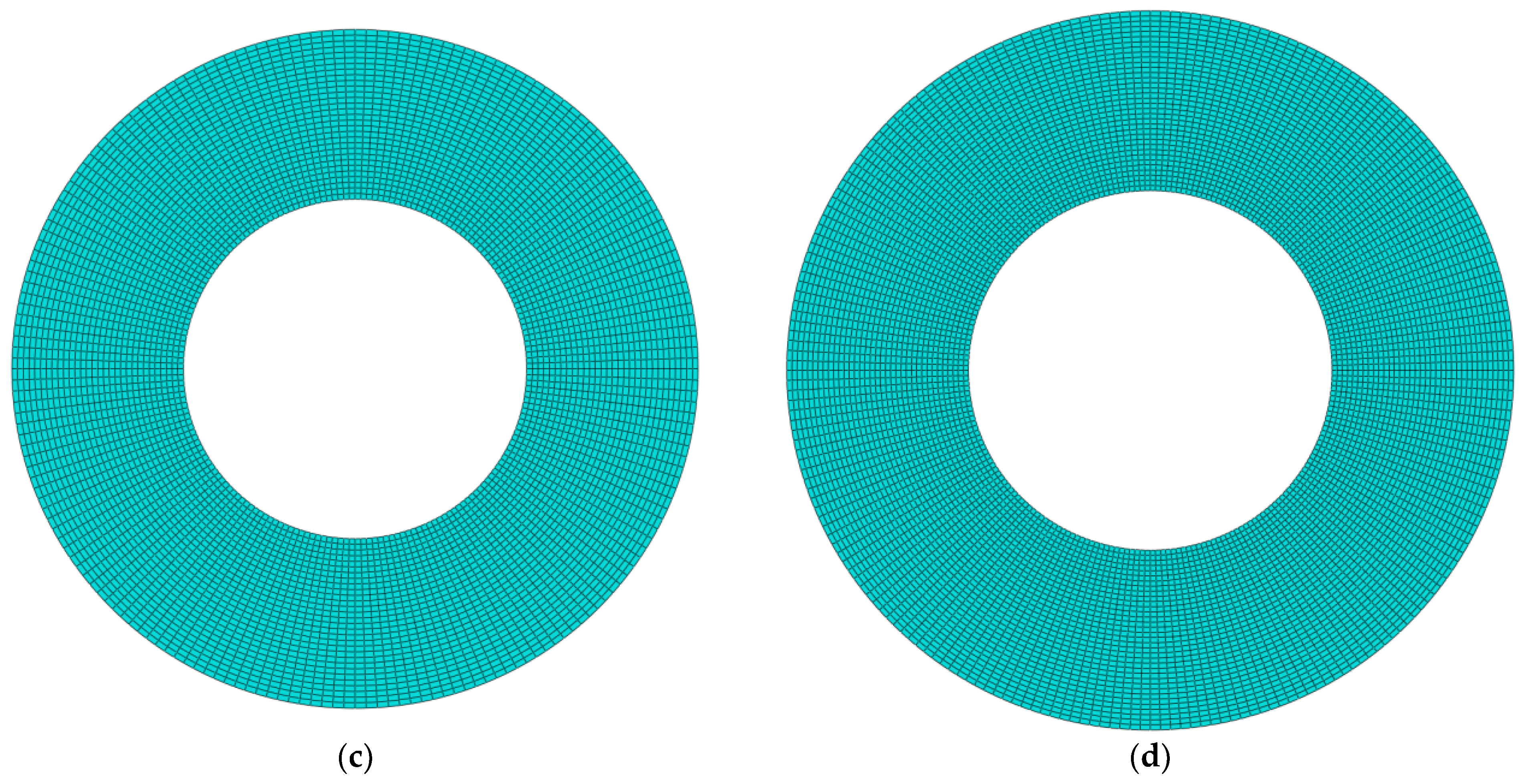
The finite element method is used to validate the present analysis by using commercial software ABAQUS. The functionally graded material core is divided into ten layers and the material properties of each layer are calculated by the equations in Section 2.2. The annular plate is clamped at the inner edge, free at its outer edge, and is discretized by 4-node doubly curved general-purpose shell elements with 6 degrees of freedom. To examine the convergence of the finite element analysis, Table 3 gives the first four natural frequencies at Ω = 500 rad/s with different total numbers of elements Ne = (1440, 4000, 5760, 7840) and nodes (1536, 4160, 5952, 8064). Figure 4 displays the corresponding mesh graphs. It is clear that the free vibration results come to be converged at element number Ne = 7840.
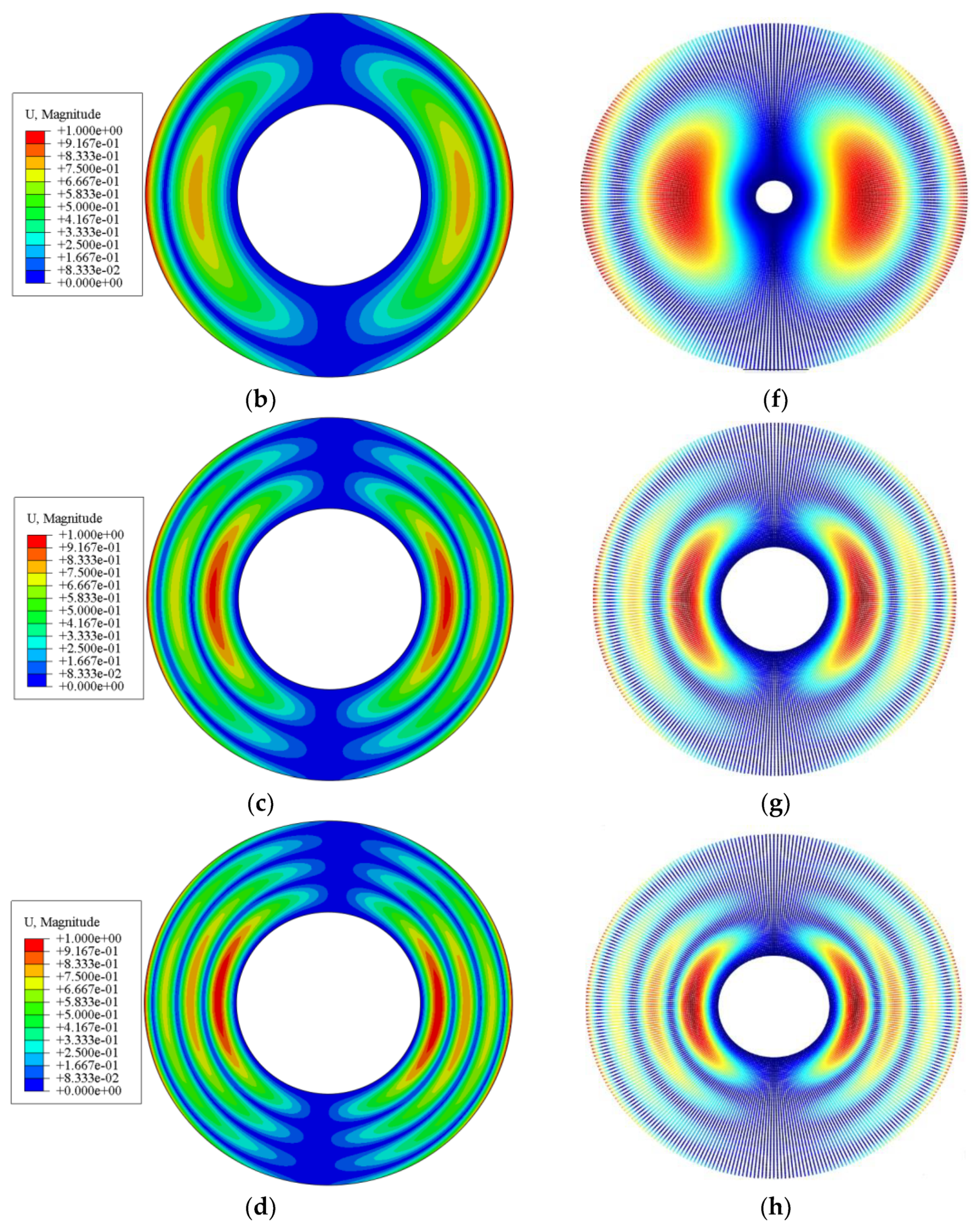
Table 4 and Figure 5 give the comparison of first four natural frequencies and vibration modes by theoretical method (MATLAB) and finite element (ABAQUS) method at Ω = 500 rad/s, respectively. It is obvious that the frequencies and vibration modes are in agreement, which shows that the present analysis is accurate.
In addition, the theoretical results are also compared with the experimental results [35] in Table 5, where the parameters are given in Table 6. One can see that the theoretical calculation results are in good agreement with the experimental results, which tells that the present analysis is accurate.
3.2. Parametric Analysis
In this section, both the graphic form and tabular form are utilized to conduct the parametric analysis on the free vibration results of the spinning FG annular plate with porous core reinforced by GPLs.
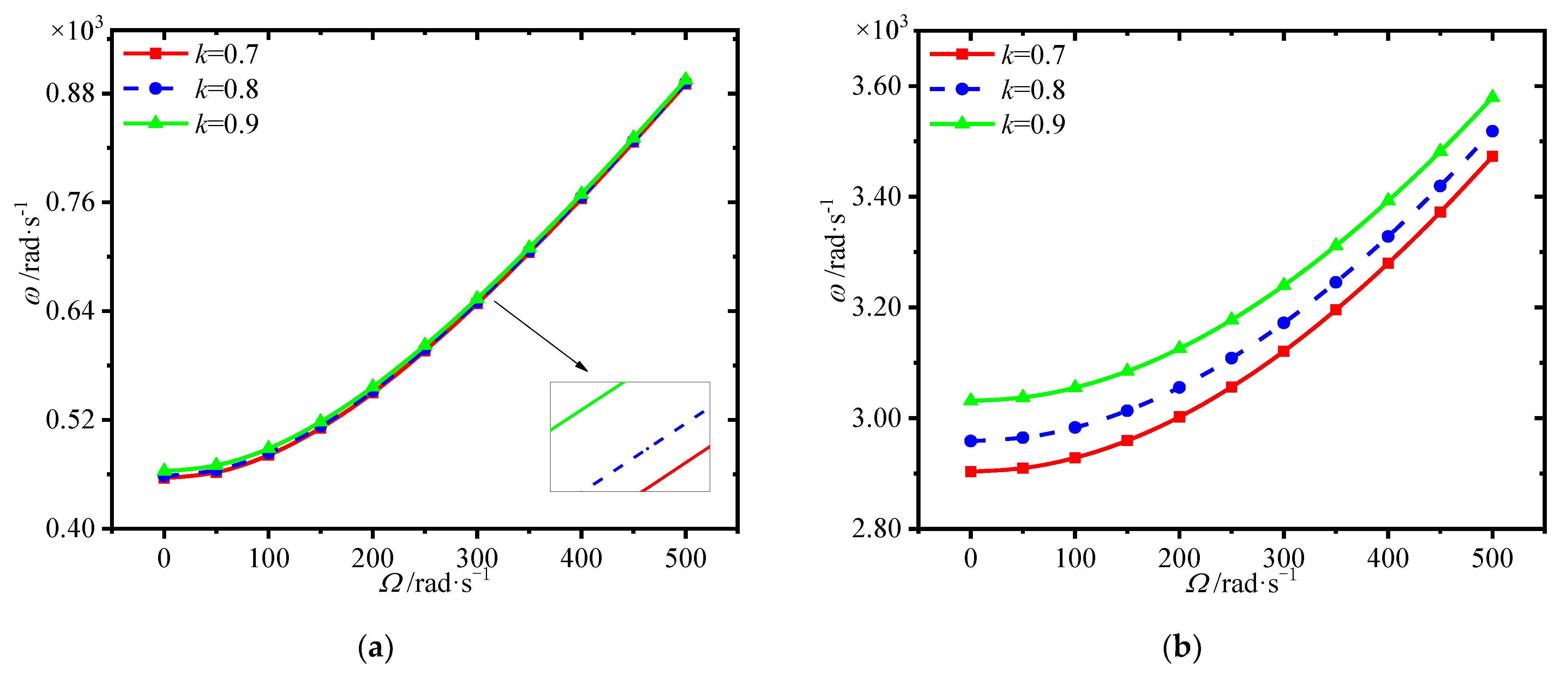
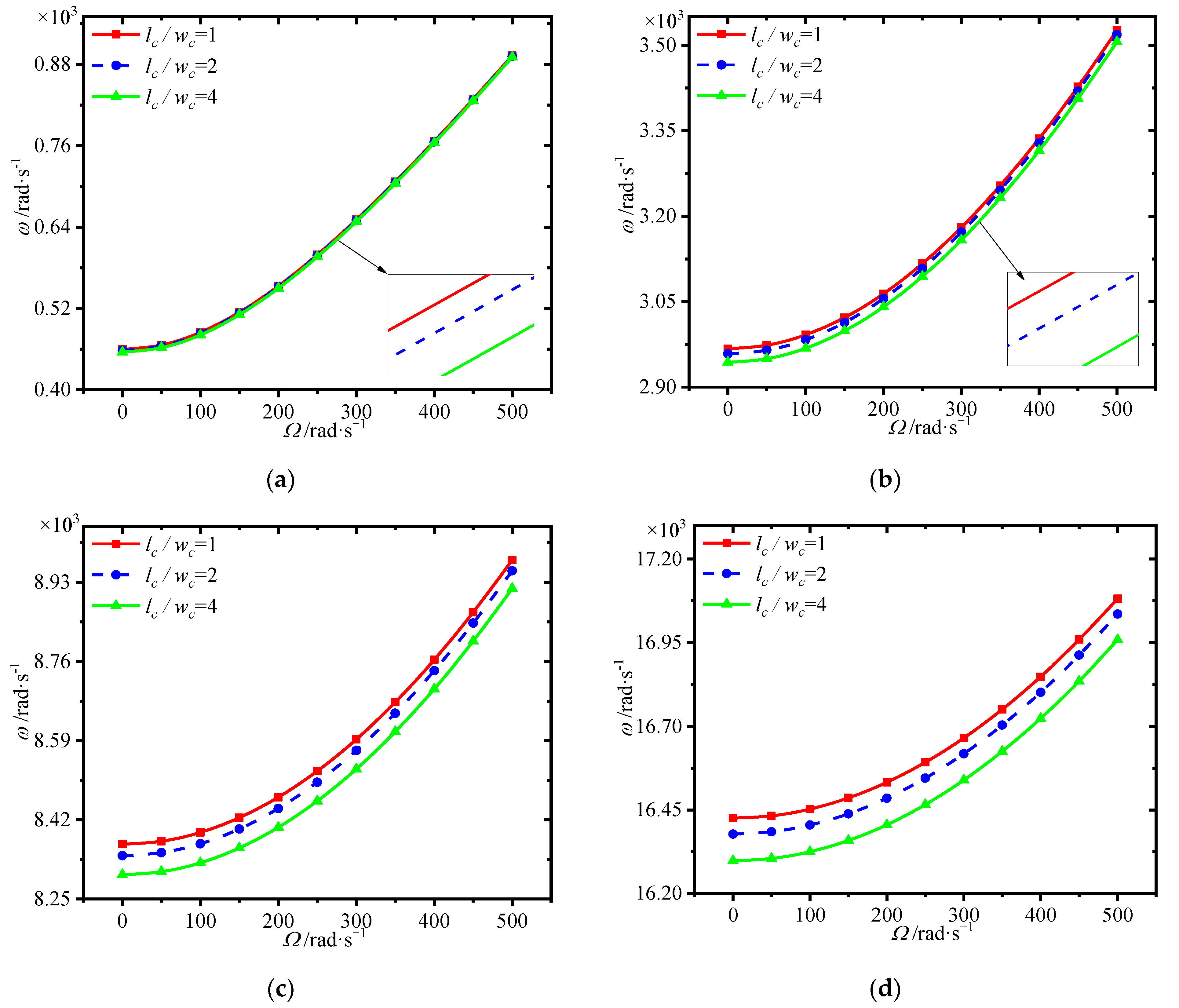
Figure 6 depicts the variations of first four natural frequencies of the annular plate with spinning speed for different ratios of the core thickness to annular plate thickness. A considerable rise in the frequencies is observed as the spinning speed increases. In addition, the larger ratio of the core thickness to annular plate thickness leads to greater frequencies. It indicates that thinner faces could be adopted in the present sandwich structure to achieve better mechanical performance.
Figure 7 plots the variations of first four natural frequencies of the annular plate with spinning speed for different GPL distributions. It is seen that the GPL distribution pattern XG provides highest frequencies, while pattern OG has the worst enhancement effect. This implies that dispersing more GPLs around the surfaces of the core could give a hand to enhance the structural stiffness.
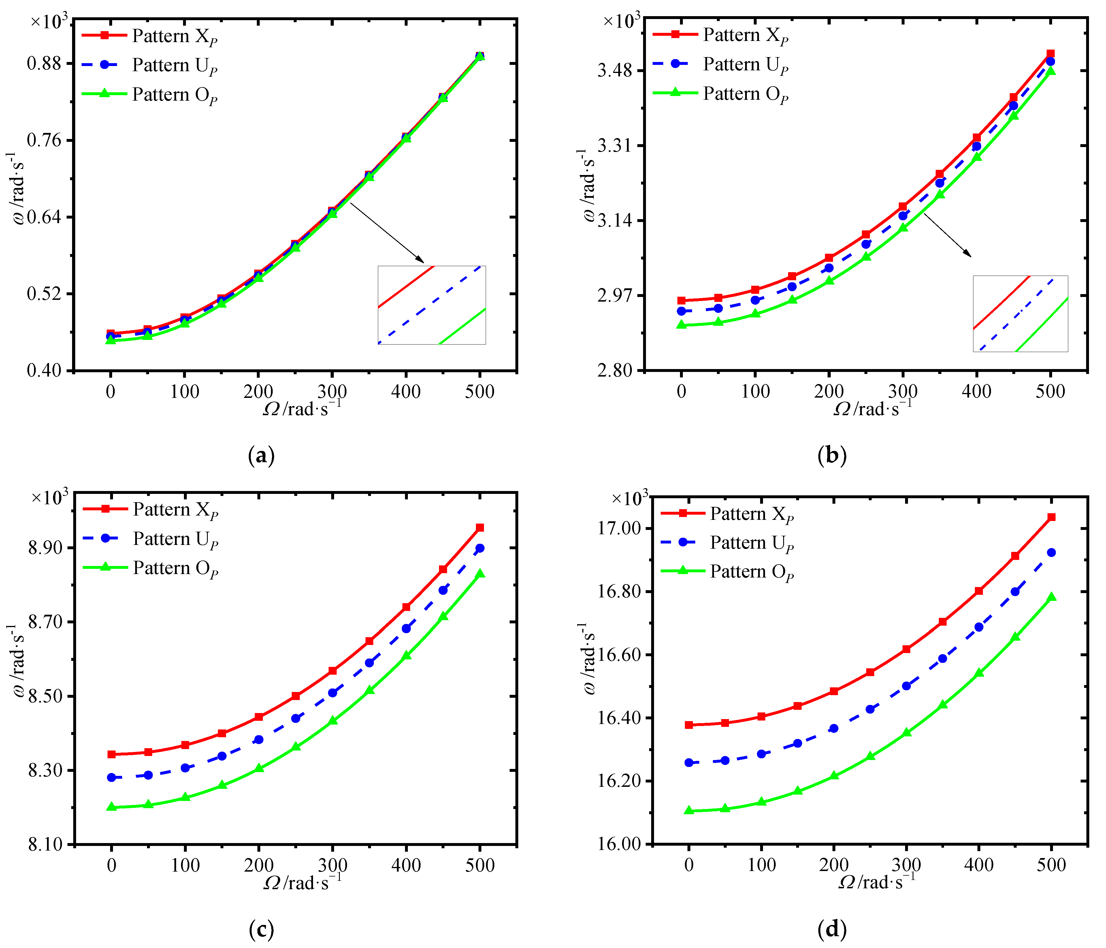
The variations of first four natural frequencies of the annular plate with spinning speed for different porosity distributions are presented in Figure 8. Results show that porosity distribution pattern XP affords greatest frequencies, while the pattern OP gives the smallest one. It is noted that setting more pores around the surfaces of the core is effective to obtain great mechanical performance.
Since the variations of natural frequencies with spinning speed are similar, only two typical spinning speeds, 0 rad/s and 500 rad/s, are adopted in the following analysis.
Figure 9 shows the variations of first four natural frequencies of the annular plate with GPL weight fraction at different spinning speeds. One can see that the frequencies increase markedly with the GPL weight fraction. It is worth noting that adding more GPLs into the core plays a very important role in obtaining greater enhancement.
Figure 10 lists the variations of first four natural frequencies of the annular plate with GPL length-to-thickness ratio at different spinning speeds. We can see that the frequencies rise dramatically with the GPL length-to-thickness ratio. For the same content of GPLs, larger GPL length-to-thickness ratio means a thinner GPL. It can be seen that better enhancement effect occurs when thinner GPLs are added into the core.
Figure 11 gives the variations of first four natural frequencies of the annular plate with GPL length-to-width ratio at different spinning speeds, where GPL length remains constant. It is seen that the frequencies are reduced with a rise in GPL length-to-width ratios. Here it should be noted that a smaller GPL length-to-width ratio means each GPL with larger surface area, which can lead to better load transfer capacity.
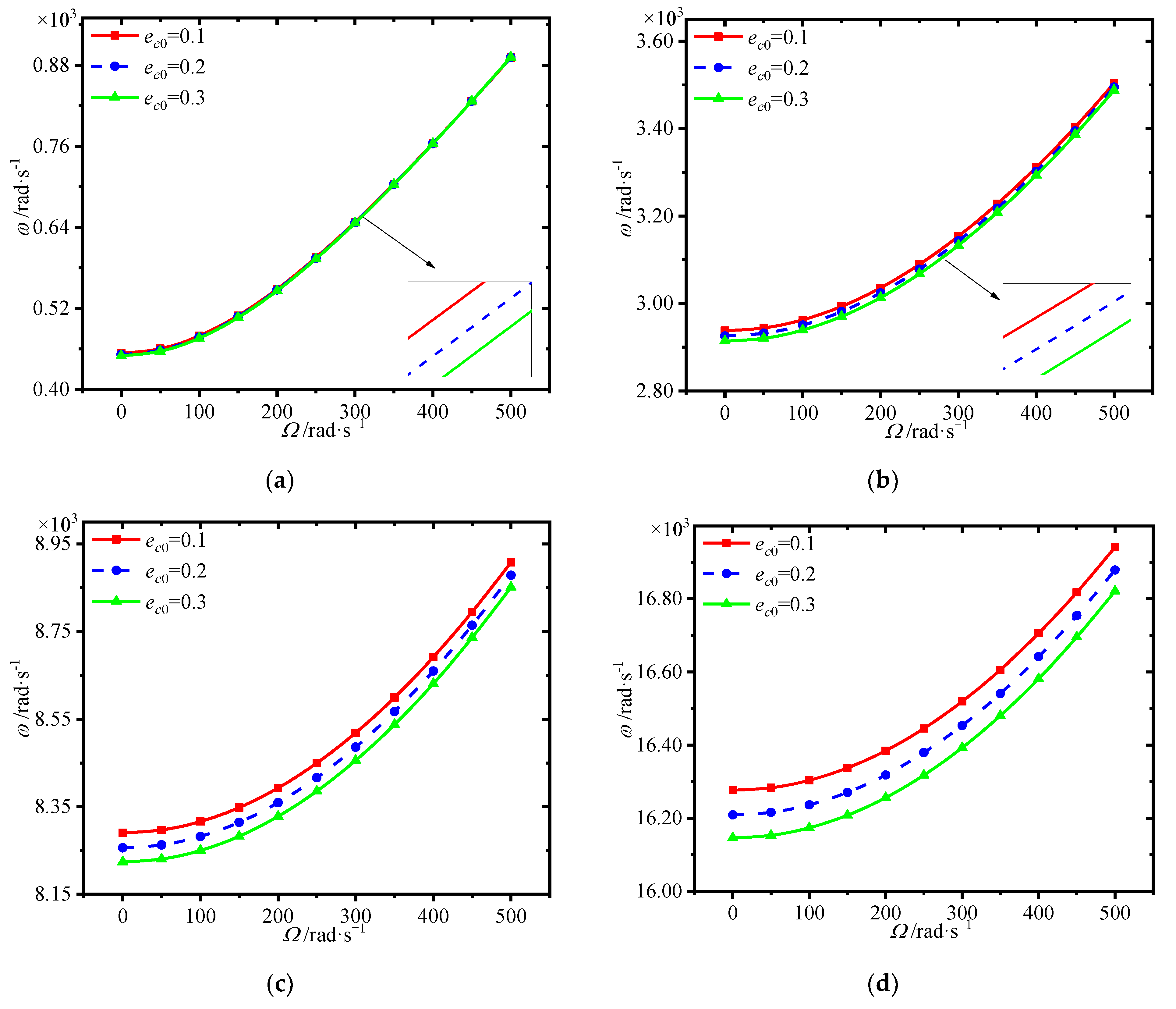
The variations of first four natural frequencies of the annular plate with porosity coefficient at different spinning speeds is presented in Figure 12. One can see that the frequencies decrease in general with the increase of porosity coefficient. Although the larger porosity coefficient can result in light weight, it weakens the structural stiffness.
4. Conclusions
This paper concerned with the free vibration behavior of a spinning FG annular plate with porous core reinforced by GPLs. Based on the Kirchhoff plate theory, the equations of motion are obtained by employing the Lagrange equation method. The model and vibration analysis are verified by adopting the FE method. Several interesting results could be noted as follows.
- (1)
- thinner faces could be adopted in the present sandwich structure to achieve better mechanical performance.
- (2)
- setting more pores and GPLs around the surfaces of the core is effective in enhancing the structural stiffness.
- (3)
- adding a few GPLs into the core plays a very important role in obtaining greater enhancement.
- (4)
- better enhance effect occurs when thinner GPLs with larger surface areas are applied to be added into the core.
- (5)
- larger porosity coefficient can result in light weight and weaken the structural stiffness.
Author Contributions
Conceptualization, J.Y.; methodology, T.H. and Y.M.; finite element analysis, T.Z.; validation, Y.M.; formal analysis, T.H. and Y.M.; investigation, T.H., T.Z. and X.W.; writing—original draft, T.H. and Y.M.; writing—review & editing, J.Y.; supervision, J.Y. and X.W.; funding acquisition, T.Z. All authors have read and agreed to the published version of the manuscript.
Funding
This project is funded by the National Science Foundation of China (No. 51805076, No. U1708255 and No. 51775093), National Science and Technology Major Project of China (J2019-I-0008-0008), and the Fundamental Research Funds for the Central Universities of China (N2105013).
Institutional Review Board Statement
Not applicable.
Informed Consent Statement
Not applicable.
Data Availability Statement
Data sharing is not applicable to this article.
Conflicts of Interest
The authors declare no conflict of interest.
Appendix A
References
- Rdzanek, W.P.; Wiciak, J.; Pawelczyk, M. Analysis of Sound Radiation from a Vibrating Elastically Supported Annular Plate Using Compatibility Layer and Radial Polynomials. J. Sound Vib. 2022, 519, 116593. [Google Scholar] [CrossRef]
- Quaegebeur, S.; Chouvion, B.; Thouverez, F. Nonlinear Dynamic Analysis of Three-Dimensional Bladed-Disks with Frictional Contact Interfaces Based on Cyclic Reduction Strategies. Int. J. Solids Struct. 2022, 236, 111277. [Google Scholar] [CrossRef]
- Prabith, K.; Praveen Krishna, I.R. Response and Stability Analysis of a Two-Spool Aero-Engine Rotor System Undergoing Multi-Disk Rub-Impact. Int. J. Mech. Sci. 2022, 213, 106861. [Google Scholar] [CrossRef]
- Mirjavadi, S.S.; Forsat, M.; Barati, M.R.; Hamouda, A.M.S. Investigating Nonlinear Forced Vibration Behavior of Multi-Phase Nanocomposite Annular Sector Plates Using Jacobi Elliptic Functions. Steel Compos. Struct. 2020, 36, 87–101. [Google Scholar]
- Liew, K.M.; Liu, F.-L. Differential Quadrature Method for Vibration Analysis of Shear Deformable Annular Sector Plates. J. Sound Vib. 2000, 230, 335–356. [Google Scholar] [CrossRef]
- Pan, W.; Ling, L.; Qu, H.; Wang, M. Coupling Dynamic Behavior of Aero-Engine Rotor System Caused by Rolling, Pitching and Yawing Maneuver Loads. Appl. Math. Model. 2022, 102, 726–747. [Google Scholar] [CrossRef]
- Yang, F.; Pei, Y.-C. A Thermal Stress Stiffening Method for Vibration Suppression of Rotating Flexible Disk with Mass-Spring-Damper System Loaded. Int. J. Mech. Sci. 2022, 213, 106860. [Google Scholar] [CrossRef]
- Maretic, R.; Glavardanov, V.; Milosevic-Mitic, V. Vibration and Stability of Rotating Annular Disks Composed of Different Materials. Arch. Appl. Mech. 2015, 85, 117–131. [Google Scholar] [CrossRef]
- Kang, N.; Raman, A. Vibrations and Stability of a Flexible Disk Rotating in a Gas-Filled Enclosure—Part 2: Experimental Study. J. Sound Vib. 2006, 296, 676–689. [Google Scholar] [CrossRef]
- Kang, J.-H. Axisymmetric Vibration of Rotating Annular Plate with Variable Thickness Subjected to Tensile Centrifugal Body Force. Int. J. Str. Stab. Dyn. 2017, 17, 1750101. [Google Scholar] [CrossRef]
- Rao, L.B.; Rao, C.K. Frequency Analysis of Annular Plates with Inner and Outer Edges Elastically Restrained and Resting on Winkler Foundation. Int. J. Mech. Sci. 2014, 81, 184–194. [Google Scholar] [CrossRef]
- Chen, H.; Wu, R.; Xie, L.; Du, J.; Yi, L.; Huang, B.; Zhang, A.; Wang, J. High-Frequency Vibrations of Circular and Annular Plates with the Mindlin Plate Theory. Arch. Appl. Mech. 2020, 90, 1025–1038. [Google Scholar] [CrossRef]
- Tan, P.; Nie, G.J. Free and Forced Vibration of Variable Stiffness Composite Annular Thin Plates with Elastically Restrained Edges. Compos. Struct. 2016, 149, 398–407. [Google Scholar] [CrossRef]
- Amini, M.H.; Soleimani, M.; Altafi, A.; Rastgoo, A. Effects of Geometric Nonlinearity on Free and Forced Vibration Analysis of Moderately Thick Annular Functionally Graded Plate. Mech. Adv. Mater. Struct. 2013, 20, 709–720. [Google Scholar] [CrossRef]
- Wang, C.Y. Fundamental Frequencies of Annular Plates with Movable Edges. J. Sound Vib. 2006, 290, 524–528. [Google Scholar] [CrossRef]
- Dong, Y.H.; Li, Y.H.; Chen, D.; Yang, J. Vibration Characteristics of Functionally Graded Graphene Reinforced Porous Nanocomposite Cylindrical Shells with Spinning Motion. Compos. Part B Eng. 2018, 145, 1–13. [Google Scholar] [CrossRef]
- Ansari, R.; Hassani, R.; Gholami, R.; Rouhi, H. Free Vibration Analysis of Postbuckled Arbitrary-Shaped FG-GPL-Reinforced Porous Nanocomposite Plates. Thin-Walled Struct. 2021, 163, 107701. [Google Scholar] [CrossRef]
- Barati, M.R.; Zenkour, A.M. Vibration Analysis of Functionally Graded Graphene Platelet Reinforced Cylindrical Shells with Different Porosity Distributions. Mech. Adv. Mater. Struct. 2019, 26, 1580–1588. [Google Scholar] [CrossRef]
- Twinkle, C.M.; Pitchaimani, J. Free Vibration and Stability of Graphene Platelet Reinforced Porous Nano-Composite Cylindrical Panel: Influence of Grading, Porosity and Non-Uniform Edge Loads. Eng. Struct. 2021, 230, 111670. [Google Scholar]
- Chai, Q.; Wang, Y.Q. Traveling Wave Vibration of Graphene Platelet Reinforced Porous Joined Conical-Cylindrical Shells in a Spinning Motion. Eng. Struct. 2022, 252, 113718. [Google Scholar] [CrossRef]
- Zhao, T.Y.; Ma, Y.; Zhang, H.Y.; Pan, H.G.; Cai, Y. Free Vibration Analysis of a Rotating Graphene Nanoplatelet Reinforced Pre-Twist Blade-Disk Assembly with a Setting Angle. Appl. Math. Model. 2021, 93, 578–596. [Google Scholar] [CrossRef]
- Zhao, T.Y.; Jiang, L.P.; Pan, H.G.; Yang, J.; Kitipornchai, S. Coupled Free Vibration of a Functionally Graded Pre-Twisted Blade-Shaft System Reinforced with Graphene Nanoplatelets. Compos. Struct. 2021, 262, 113362. [Google Scholar] [CrossRef]
- Zhao, T.Y.; Cui, Y.S.; Pan, H.G.; Yuan, H.Q.; Yang, J. Free Vibration Analysis of a Functionally Graded Graphene Nanoplatelet Reinforced Disk-Shaft Assembly with Whirl Motion. Int. J. Mech. Sci. 2021, 197, 106335. [Google Scholar] [CrossRef]
- Zhao, T.Y.; Cui, Y.S.; Wang, Y.Q.; Pan, H.G. Vibration Characteristics of Graphene Nanoplatelet Reinforced Disk-Shaft Rotor with Eccentric Mass. Mech. Adv. Mater. Struct. 2021, 1–21. [Google Scholar] [CrossRef]
- Adab, N.; Arefi, M.; Amabili, M. A Comprehensive Vibration Analysis of Rotating Truncated Sandwich Conical Microshells Including Porous Core and GPL-Reinforced Face-Sheets. Compos. Struct. 2022, 279, 114761. [Google Scholar] [CrossRef]
- Saidi, A.R.; Bahaadini, R.; Majidi-Mozafari, K. On Vibration and Stability Analysis of Porous Plates Reinforced by Graphene Platelets under Aerodynamical Loading. Compos. Part B Eng. 2019, 164, 778–799. [Google Scholar] [CrossRef]
- Li, Q.; Wu, D.; Chen, X.; Liu, L.; Yu, Y.; Gao, W. Nonlinear Vibration and Dynamic Buckling Analyses of Sandwich Functionally Graded Porous Plate with Graphene Platelet Reinforcement Resting on Winkler–Pasternak Elastic Foundation. Int. J. Mech. Sci. 2018, 148, 596–610. [Google Scholar] [CrossRef]
- Zhou, X.; Wang, Y.; Zhang, W. Vibration and Flutter Characteristics of GPL-Reinforced Functionally Graded Porous Cylindrical Panels Subjected to Supersonic Flow. Acta Astronaut. 2021, 183, 89–100. [Google Scholar] [CrossRef]
- Gao, K.; Gao, W.; Chen, D.; Yang, J. Nonlinear Free Vibration of Functionally Graded Graphene Platelets Reinforced Porous Nanocomposite Plates Resting on Elastic Foundation. Compos. Struct. 2018, 204, 831–846. [Google Scholar] [CrossRef]
- Baghlani, A.; Najafgholipour, M.A.; Khayat, M. The Influence of Mechanical Uncertainties on the Free Vibration of Functionally Graded Graphene-Reinforced Porous Nanocomposite Shells of Revolution. Eng. Struct. 2021, 228, 111356. [Google Scholar] [CrossRef]
- Anamagh, M.R.; Bediz, B. Free Vibration and Buckling Behavior of Functionally Graded Porous Plates Reinforced by Graphene Platelets Using Spectral Chebyshev Approach. Compos. Struct. 2020, 253, 112765. [Google Scholar] [CrossRef]
- Anirudh, B.; Ganapathi, M.; Anant, C.; Polit, O. A Comprehensive Analysis of Porous Graphene-Reinforced Curved Beams by Finite Element Approach Using Higher-Order Structural Theory: Bending, Vibration and Buckling. Compos. Struct. 2019, 222, 110899. [Google Scholar] [CrossRef]
- Kitipornchai, S.; Chen, D.; Yang, J. Free vibration and elastic buckling of functionally graded porous beams reinforced by graphene platelets. Mater. Des. 2017, 116, 656–665. [Google Scholar] [CrossRef]
- Zhao, S.Y.; Zhao, Z.; Yang, Z.C.; Ke, L.L.; Kitipornchai, S.; Yang, J. Functionally graded graphene reinforced composite structures: A review. Eng. Struct. 2020, 210, 110339. [Google Scholar] [CrossRef]
- D’Angelo, C.; Mote, C.D. Natural Frequencies of A Thin Disk, Clamped By Thick Collars With Friction At The Contacting Surfaces, Spinning At High Rotation Speed. J. Sound Vib. 1993, 168, 1–14. [Google Scholar] [CrossRef]
Figure 1.
The spinning annular plate model with GPL reinforced porous core and solid faces.

Figure 2.
Porosity distribution patterns for the core of the annular plate. (a) Pattern XP; (b) Pattern UP; (c) Pattern OP.
Figure 2.
Porosity distribution patterns for the core of the annular plate. (a) Pattern XP; (b) Pattern UP; (c) Pattern OP.

Figure 3.
GPL distribution patterns for the core of the annular plate. (a) Pattern XG (b) Pattern UG (c) Pattern OG.
Figure 3.
GPL distribution patterns for the core of the annular plate. (a) Pattern XG (b) Pattern UG (c) Pattern OG.

Figure 4.
Mesh graph of different mesh element numbers. (a) Ne = 1440 (b) Ne = 4000, (c) Ne = 5760 (d) Ne = 7840.
Figure 4.
Mesh graph of different mesh element numbers. (a) Ne = 1440 (b) Ne = 4000, (c) Ne = 5760 (d) Ne = 7840.


Figure 5.
Vibration modes of the spinning annular plate: (a–d) are the first four vibration modes obtained by ABAQUS; (e–h) are the first four vibration modes obtained by MATLAB.
Figure 5.
Vibration modes of the spinning annular plate: (a–d) are the first four vibration modes obtained by ABAQUS; (e–h) are the first four vibration modes obtained by MATLAB.


Figure 6.
Variations of first four natural frequencies (rad/s) with spinning speed for different ratio of the core thickness to annular plate thickness. (a) first frequency (b) second frequency, (c) third frequency (d) fourth frequency.
Figure 6.
Variations of first four natural frequencies (rad/s) with spinning speed for different ratio of the core thickness to annular plate thickness. (a) first frequency (b) second frequency, (c) third frequency (d) fourth frequency.


Figure 7.
Variations of first four natural frequencies (rad/s) with spinning speed for different GPL distributions. (a) first frequency (b) second frequency, (c) third frequency (d) fourth frequency.
Figure 7.
Variations of first four natural frequencies (rad/s) with spinning speed for different GPL distributions. (a) first frequency (b) second frequency, (c) third frequency (d) fourth frequency.

Figure 8.
Variations of first four natural frequencies (rad/s) with spinning speed for different porosity distributions. (a) first frequency (b) second frequency, (c) third frequency (d) fourth frequency.
Figure 8.
Variations of first four natural frequencies (rad/s) with spinning speed for different porosity distributions. (a) first frequency (b) second frequency, (c) third frequency (d) fourth frequency.

Figure 9.
Variations of first four natural frequencies (rad/s) with GPL weight fraction for different spinning speeds. (a) first frequency (b) second frequency, (c) third frequency (d) fourth frequency.
Figure 9.
Variations of first four natural frequencies (rad/s) with GPL weight fraction for different spinning speeds. (a) first frequency (b) second frequency, (c) third frequency (d) fourth frequency.

Figure 10.
Variations of first four natural frequencies (rad/s) with GPL length-to-thickness ratio for different spinning speeds. (a) first frequency (b) second frequency, (c) third frequency (d) fourth frequency.
Figure 10.
Variations of first four natural frequencies (rad/s) with GPL length-to-thickness ratio for different spinning speeds. (a) first frequency (b) second frequency, (c) third frequency (d) fourth frequency.


Figure 11.
Variations of first four natural frequencies (rad/s) with GPL length-to-width ratio for different spinning speeds. (a) first frequency (b) second frequency, (c) third frequency (d) fourth frequency.
Figure 11.
Variations of first four natural frequencies (rad/s) with GPL length-to-width ratio for different spinning speeds. (a) first frequency (b) second frequency, (c) third frequency (d) fourth frequency.

Figure 12.
Variations of first four natural frequencies (rad/s) with porosity coefficient for different spinning speeds. (a) first frequency (b) second frequency, (c) third frequency (d) fourth frequency.
Figure 12.
Variations of first four natural frequencies (rad/s) with porosity coefficient for different spinning speeds. (a) first frequency (b) second frequency, (c) third frequency (d) fourth frequency.


Table 1.
The structural and material parameters.
| Parameters | Value |
|---|---|
| Ra | 0.5 m |
| Rb | 1 m |
| h | 0.02 m |
| k | 0.8 |
| EGPL | 1010 GPa |
| ρGPL | 1062.5 kg/m3 |
| μGPL | 0.186 |
| EM | 68.3 GPa |
| Ef | 68.3 GPa |
| ρM | 2689.8 kg/m3 |
| ρf | 2689.8 kg/m3 |
| μM | 0.34 |
| μf | 0.34 |
| WGPL | 0.67% |
| lc/tc | 100 |
| Lc/wc | 2 |
| ec0 | 0.1 |
Table 2.
First four natural frequencies (rad/s) of the spinning annular plate with different mode numbers (Ω = 500 rad/s).
Table 2.
First four natural frequencies (rad/s) of the spinning annular plate with different mode numbers (Ω = 500 rad/s).
| Frequency (rad/s) | n = 4 | n = 5 | n = 6 | n = 7 |
|---|---|---|---|---|
| First | 892.13 | 892.06 | 892.02 | 892.01 |
| Second | 3518.88 | 3518.56 | 3518.44 | 3518.36 |
| Third | 8955.60 | 8954.89 | 8954.70 | 8954.58 |
| Fourth | 17,039.40 | 17,035.83 | 17,035.43 | 17,035.32 |
Table 3.
First four natural frequencies (rad/s) of the spinning annular plate with different element numbers by finite element (FE) method (Ω = 500 rad/s).
Table 3.
First four natural frequencies (rad/s) of the spinning annular plate with different element numbers by finite element (FE) method (Ω = 500 rad/s).
| Frequency (Hz) | Ne = 1440 | Ne = 4000 | Ne = 5760 | Ne = 7840 |
|---|---|---|---|---|
| First | 140.96 | 140.82 | 140.80 | 140.79 |
| Second | 555.15 | 551.85 | 551.29 | 550.95 |
| Third | 1421.00 | 1395.70 | 1391.50 | 1388.90 |
| Fourth | 2728.30 | 2630.20 | 2613.90 | 2604.10 |
Table 4.
Comparison of first four natural frequencies of the spinning annular plate by theory method and finite element (FE) method (Ω = 500 rad/s).
Table 4.
Comparison of first four natural frequencies of the spinning annular plate by theory method and finite element (FE) method (Ω = 500 rad/s).
| Frequency | Present (Hz) | FE (Hz) | Error |
|---|---|---|---|
| First | 141.97 | 140.79 | 0.84% |
| Second | 559.98 | 550.95 | 1.64% |
| Third | 1425.18 | 1388.90 | 2.61% |
| Fourth | 2711.27 | 2604.10 | 4.12% |
Table 5.
Comparison of first two natural frequencies of a spinning annular plate between theory method and experiment method [35] (Ω = 0 rad/s).
Table 5.
Comparison of first two natural frequencies of a spinning annular plate between theory method and experiment method [35] (Ω = 0 rad/s).
| Frequency | Present (Hz) | Experiment (Hz) | Error |
|---|---|---|---|
| First | 38.95 | 37.19 ± 0.29 | 4.73% |
| Second | 265.35 | 262.38 ± 1.42 | 1.01% |
Table 6.
The structural and material parameters in the literature [35].
Table 6.
The structural and material parameters in the literature [35].
| Parameter | Value |
|---|---|
| Ra | 178 mm |
| Rb | 53.35 mm |
| h | 0.775 mm |
| E | 200 GPa |
| ρ | 7840 kg/m3 |
| μ | 0.3 |
Publisher’s Note: MDPI stays neutral with regard to jurisdictional claims in published maps and institutional affiliations. |
© 2022 by the authors. Licensee MDPI, Basel, Switzerland. This article is an open access article distributed under the terms and conditions of the Creative Commons Attribution (CC BY) license (https://creativecommons.org/licenses/by/4.0/).
Share and Cite
MDPI and ACS Style
Huang, T.; Ma, Y.; Zhao, T.; Yang, J.; Wang, X. Free Vibration Analysis of Spinning Sandwich Annular Plates with Functionally Graded Graphene Nanoplatelet Reinforced Porous Core. Materials 2022, 15, 1328. https://doi.org/10.3390/ma15041328
AMA Style
Huang T, Ma Y, Zhao T, Yang J, Wang X. Free Vibration Analysis of Spinning Sandwich Annular Plates with Functionally Graded Graphene Nanoplatelet Reinforced Porous Core. Materials. 2022; 15(4):1328. https://doi.org/10.3390/ma15041328
Chicago/Turabian StyleHuang, Tianhao, Yu Ma, Tianyu Zhao, Jie Yang, and Xin Wang. 2022. "Free Vibration Analysis of Spinning Sandwich Annular Plates with Functionally Graded Graphene Nanoplatelet Reinforced Porous Core" Materials 15, no. 4: 1328. https://doi.org/10.3390/ma15041328
Note that from the first issue of 2016, this journal uses article numbers instead of page numbers. See further details here.