Article

Destructive and Non-Destructive Testing of the Performance of Copper Slag Fiber-Reinforced Concrete

by
Vijayaprabha Chakrawarthi
1,
Brindha Dharmar
2,
Siva Avudaiappan
3,*,
Mugahed Amran
4,5,*,
Erick Saavedra Flores
6,
Mohammad Ayaz Alam
7,
Roman Fediuk
8,9,
Nikolai Ivanovich Vatin
9 and
Raizal S. M. Rashid
10
1
Department of Civil Engineering, Alagappa Chettiar Government College of Engineering and Technology, Karaikudi 630003, India
2
Department of Civil Engineering, Thiagarajar College of Engineering, Madurai 625015, India
3
Departamento de Ingeniería Civil, Universidad de Concepción, Concepción 4030000, Chile
4
Department of Civil Engineering, College of Engineering, Prince Sattam Bin Abdulaziz University, Alkharj 16273, Saudi Arabia
5
Department of Civil Engineering, Faculty of Engineering and IT, Amran University, Amran 9677, Yemen
6
Departamento de Ingeniería en Obras Civiles, University of Santiago of Chile, Av. Ecuador 3659, Santiago 9170201, Chile
7
Departamento de Geología, Facultad de Ingeniería, Universidad de Atacama, Avenida Copayapu 485, Copiapó 1531772, Región de Atacama, Chile
8
Polytechnic Institute, Far Eastern Federal University, 690922 Vladivostok, Russia
9
Peter the Great St. Petersburg Polytechnic University, 195251 St. Petersburg, Russia
10
Department of Civil Engineering, Faculty of Engineering, Universiti Putra Malaysia, Serdang 43400, Malaysia
*
Authors to whom correspondence should be addressed.
Materials 2022, 15(13), 4536; https://doi.org/10.3390/ma15134536
Submission received: 12 May 2022 / Revised: 17 June 2022 / Accepted: 23 June 2022 / Published: 28 June 2022

Abstract

:
Concrete technology is adopted worldwide in construction due to its effectiveness, performance, and price benefits. Subsequently, it needs to be an eco-friendly, sustainable, and energy-efficient material. This is achieved by replacing or adding energy-efficient concrete materials from industries, such as ground granulated blast furnace slag, steel slag, fly ash, bottom ash, rice husk ash, etc. Likewise, copper slag is a waste material produced as molten slag from the copper industry, which can be used in concrete production. Copper slag can perform roles similar to pozzolans in the hydration process. This paper extends the comparative study of copper slag concrete with polypropylene fiber (PPF) subjected to destructive and non-destructive testing. Under destructive testing, compressive strength of concrete cubes, compressive strength of mortar cubes, splitting tensile tests on cylindrical specimens, and flexural tests on plain cement concrete were conducted and analysed. Ultrasonic pulse velocity and rebound hammer tests were performed on the samples as per IS13311-Part 1-1992 for non-destructive testing. The 100% replacement of copper slag exhibited a very high workability of 105 mm, while the addition of 0.8% PPF decreased the flowability of the concrete. Hence, the workability of concrete decreases as the fiber content increases. The density of the concrete was found to be increased in the range of 5% to 10%. Furthermore, it was found that, for all volume fractions of fiber, there was no reduction in compressive strength of up to 80% of copper slag concrete compared to control concrete. The 40% copper slag concrete was the best mix proportion for increasing compressive strength. However, for cement mortar applications, 80% copper slag is recommended. The findings of non-destructive testing show that, except for 100% copper slag, all mixes were of good quality compared to other mixes. Linear relationships were developed to predict compressive strength from UPV and rebound hammer test values. This relationship shows better prediction among dependent and independent values. It is concluded that copper slag has a pozzolanic composition, and is compatible with PPF, resulting in good mechanical characteristics.

1. Introduction

Concrete is a versatile material, popular for its low cost and adaptability [1]. It is the second-largest material consumed by humanity, second only to water [2]. Concrete is a composite paste of calcareous and argillaceous material, such as cement, sand, and coarse aggregate, mixed with water [3]. A material other than cement water, known as an aggregate, provides high dimensional stability to the concrete, since 55–80% of the concrete volume consists of aggregates. It also determines the particle packing and strength of the concrete. Each material contributes a unique property to develop a homogeneous mass. The total construction cost depends on the number of individual constituents. Among these materials, sand and aggregates are the non-renewable resources under the highest demand among construction industries [4]. The availability of sand is diminishing, and its cost is increasing daily [5,6].
Natural resources are diminishing at their source due to recent development in urbanization and industrialization. Sand is one of such natural resources disappearing daily due to large mining operations utilized for construction [7]. The illegal mining of river sand near the river bed affects the surrounding ecology; aquatic mining also leads to soil erosion, intrusion of seawater, and water contamination, etc. Altogether, some of the industrial wastes disposed of into open land cause environmental pollution and contaminate nearby water bodies, leading to severe health hazards and loss of aquatic life [8]. Industrial waste faces problems in terms of disposal methods, increasing costs of disposal, health hazard issues in metal recovery and water treatment industries, etc., and needs sustainable decisions for the safe and productive disposal of waste [7,9]. Industrial wastes have advantageous components, such as silica, calcium oxide, ferrous metals, etc., which can produce harder mass when incorporated into concrete [10]. As a solution to river sand scarcity and industrial waste recycling, such wastes can be substituted into cement, aggregate, or both, resulting in sustainable concrete and green technology [11,12,13,14,15].
Researchers are interested in replacing bottom ash, blast furnace slag [1], copper slag, steel slag, furnace slag, iron scales, ceramic waste, e-waste, marble dust, and recycled aggregate in the place of river sand in concrete [4,5,7,8,9,10,11,12]. Reportedly, slag is the 16th element used in creating high-performance concrete [16], and is known as a supplemental cementitious material (SCM) [17], which can improve the strength and durability of concrete [18]. With a surface area of 400–600 m2/kg and a bulk density of 1200 kg/m3, fine slag powder may be combined with free lime to replace 40–65% of total cement content. On the other hand, the coarser slag powder can be employed as an aggregate substitute in the concrete matrix [19]. Despite its low hydration activity, the slag has cementitious properties similar to ordinary Portland cement (OPC) [20,21,22,23,24]. As a result, slag has several advantages in manufacturing concrete [20,21,22,23]. It decreases cement hydration heat, improves long-term compressive strength, increases durability, and considerably reduces the adiabatic temperature rise in concrete [24,25]. Ground granulated blast furnace slag is one form of slag that can be used to replace the high cement content in concrete [26]. However, it may have lower mechanical strength [27].
Furthermore, because of the large particle size of slag, it has weaker cementing characteristics, which may decrease the bond between slag particles and calcium–silicate–hydrate gels [28,29]. Under significant volumes of steel slag, coarser pore structures can emerge [30], reducing concrete strength and durability [31]. However, earlier research has found that a slag-based composite binder can minimize setting time, enhance concrete rheology, refine porosity, and provide sufficient compressive strength [32,33]. In a previous study, the composite binder displayed decreased hydration heat, and the concrete adiabatic temperature rose compared to another common additive—flying ash [32]. The GGBFS exhibits a good pozzolanic response, absorbing Ca(OH)2 to react with sulfate and reducing gypsum [34]. Due to the development of C–S–H gels via a pozzolanic reaction, the resulting slag concrete is denser and has better sulfate resistance [35].
Copper slag is a waste derivative obtained from the smelting and refining process during copper separation from copper ore [1]. Using copper slag in cement and concrete enhances the quality of concrete, providing an environmentally sustainable material with cost-effectiveness [36]. Copper slag is widely used in the sandblasting industry and in manufacturing abrasive tools, such as cutting, polishing, and grinding tools [37]. Many works in the literature testify that copper slag is one of the alternates to fine aggregates, and can also possibly produce good concrete. Copper slag holds a high specific gravity; hence, the concrete is 5% denser than ordinary concrete [38].
Moreover, copper slag has an irregular glassy texture that does not absorb large quantities of water [39,40]. Therefore, the water absorption rate in copper slag is meager compared to river sand. In addition, its irregular texture results in sharp edges that provide better bonding between aggregate cement matrixes, and thus make a more robust interfacial zone [41]. Therefore, the workability of concrete improves due to the lower absorption rate of copper slag. However, in the case of more extensive substitution of copper slag, the lower water absorption rate affects the performance of fresh concrete properties [40]. Reportedly, 80–100% replacement lead to aggregate settlement and the floating of excess water, resulting in bleeding and segregation [42,43].
The effect of copper slag on concrete strength after a 56- and 90-day curing period evidenced higher concrete strength, and in no case was the strength reduced. Additionally, each mix has a variation of high strength values compared to ordinary concrete [44,45]. The graph profile shows a gentle slope of increasing compressive strength up to 50% copper slag, and, in the case of tensile strength, up to 40% copper slag replacement [46]. The sharp and irregular texture ensures better particle packing under pressure, reducing the stress at critical points. The voids are filled with water, and the cement–copper slag matrix reduces voids by up to 40% [47,48]. A combination of cement, copper slag, and water-produced concrete mortars incorporating copper slag exhibit 1.14 times higher compressive strength [40]. ASTM fixed criteria for a pozzolan requires that the total percentage of silica, alumina, and ferric oxide should be more than 70%. In the case of copper slag, it was found to be around 95%. Therefore, copper slag is proven to be a high-quality pozzolanic material. The heavy metal leaching was analyzed, and all heavy metals were under safe limits, even in extremely hostile situations. Some studies have included 2% hydraulic lime to accelerate the pozzolanic reaction [49,50,51].
Slag concrete was also found to show better durability and higher corrosion resistance [51]. The ferric oxide content in copper slag makes the concrete susceptible to acid attack [52,53]. At the same time, copper slag concrete shows superior performance in protecting the concrete against sulfate attack in the case of fine aggregate replacement, wherein the resistance is comparatively low when copper slag is replaced by cement [51]. Polypropylene fiber is added to enhance flexural, tensile, toughness, and impact properties [54,55,56]. PPFs above 0.2% in volume show a reduction in workability [57,58], and fiber content beyond 1% reduces the strength [59,60]. Use of staple or fibrillated fiber instead of monofilament fiber showed increased compressive strength (14.60–17.31%), splitting tensile strength (8.88–13.35%), and modulus of rupture (8.99–24.60%), and decreased shrinkage stain (0.862 to 0.871) [61,62,63]. Very few researchers to date have concentrated on fully replacing copper slag in concrete and cement mortar applications. Moreover, none of the previous studies considered copper slag concrete combined with PPF. Hence, this experimental work concentrates on the assessment of workability parameters, density variation of concrete, compressive strength of concrete, mortar compressive strength, and non-destructive evaluation of different replacements of copper slag and polypropylene fiber. Copper slag replacement levels are 20%, 40%, 60%, 80%, and 100% regarding river sand, whereas the PPF volume fraction ranges are 0.2%, 0.4%, 0.6%, and 0.8%.

2. Materials and Methods
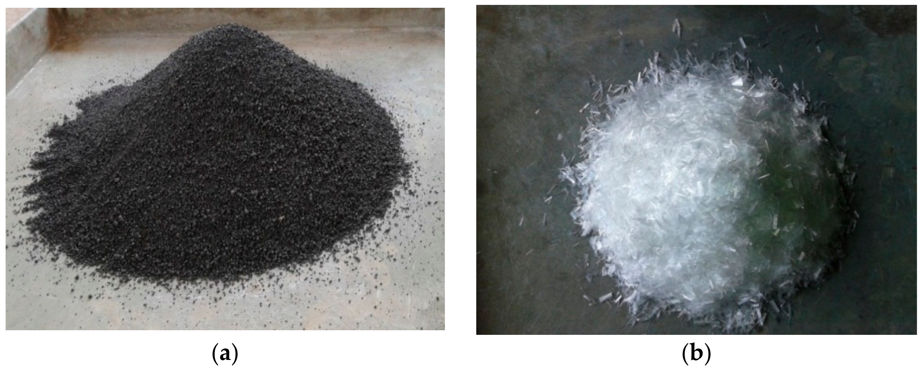
2.1. Materials

Ordinary Portland cement (OPC, 43 grade conforming to IS 8112-2013 [64]) was used throughout this study. Crushed stone aggregate of 20 mm maximum size, was used as coarse aggregate. River sand was combined with a suitable proportion of copper slag purchased from the Sterlite Corporation of India, Tuticorin. Drinking water is used for concreting works. Naphthalene-based superplasticizer Conplast SP430 was used. The dosage was fixed as 0.5% of the weight of cement. Fibrillated polypropylene fiber of 0.91 kg/m3 density was obtained from Jeetmull Pvt Ltd., Chennai, India. Figure 1a,b shows images of the copper slag and fibrillated polypropylene fiber. Aggregates were tested conforming to IS 2386-1963 [65] codal provisions; the tabulated physical properties are presented in Table 1.
From the obtained results of fundamental properties of copper slag, it was noted that the water absorption was 88% lower than for the sand. When copper slag is replaced at a higher rate, the unoccupied moisture content accumulates [66]. Surplus concrete water accelerates the hydration process, and bleeds in 100% replacement. The chemical composition of cement, copper slag, sand, and PPF are compared in Table 2. The chemical compositions of various ingredients were obtained using the XRD technique.

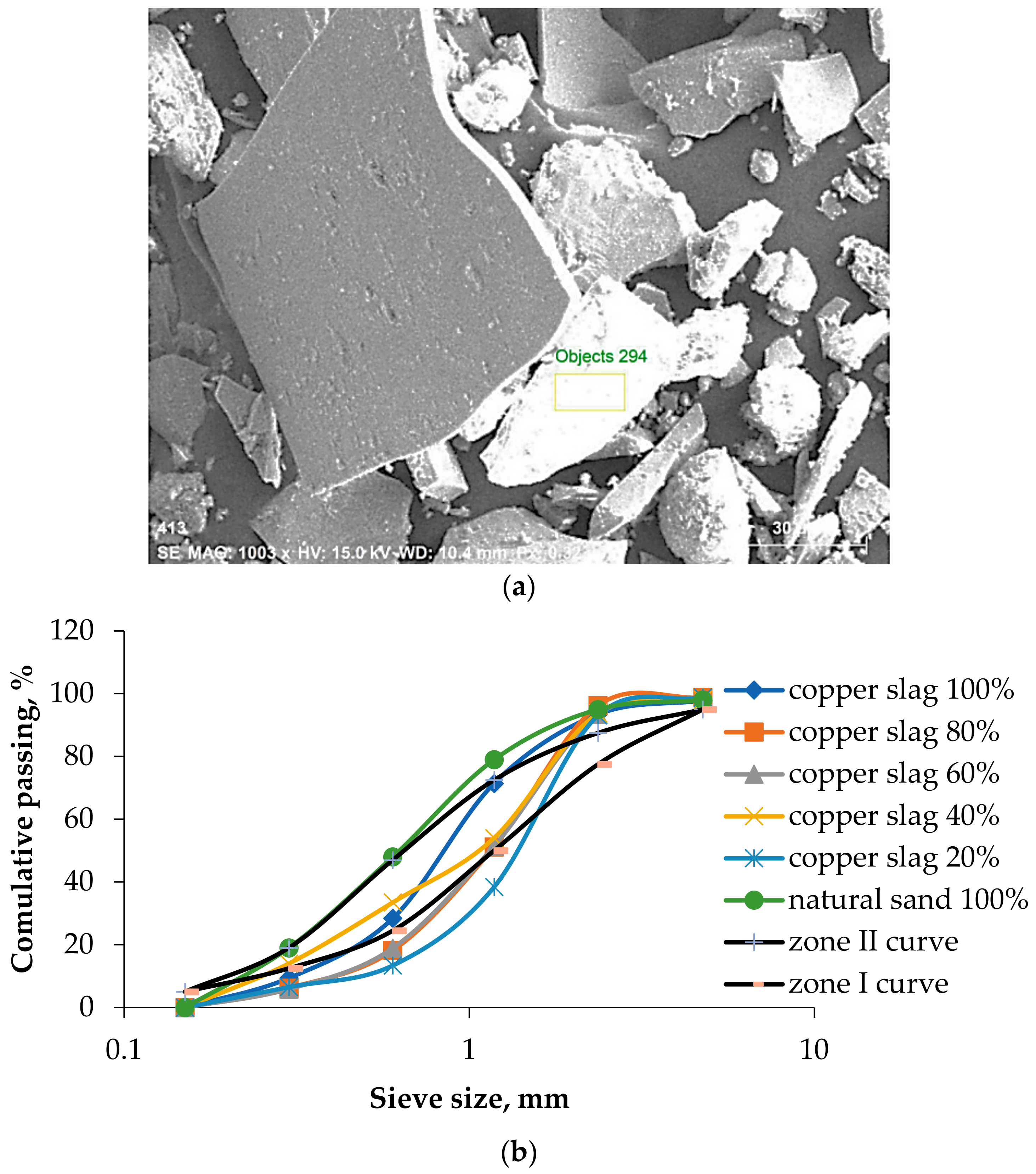
2.2. Gradation of Fine Aggregate

Copper slag particles are available from 4.75 mm to 0.075 mm in size and exhibit a proper grading and good particle packing. Figure 2a shows the particle size of copper slag on a 30 µ scale. Copper slag constitutes a 90% high-stability glassy material that does not absorb or allow water to penetrate. This property attributes the prevention of moisture intrusion inside the concrete, providing long life to the structure. Since copper slag is a high specific gravity material, the equivalent weight of copper slag to the quantum weight of natural sand is higher. In addition, the particles are densely packed among cement particles and coarse aggregates in concrete. Based on sieve analysis, 40% and 100% copper slag have the same percentage passing as sand. All proportions come under zones II and III of the Indian standard classification [67,68]. From the semi-log graph shown in Figure 2b, it is clear that 20% and 60% are deviating more from the natural sand. From these results, it was concluded that copper slag can be used as a fine aggregate without any alteration in grading.

2.3. Concrete Proportioning

Concrete proportioning was conducted on copper slag replacement from 0% to 100% and fibrillated polypropylene fiber from 0% to 0.8%, in increments of 20% and 0.2%, respectively. Cement mortars were cast on a 1:3 ratio, in which the sand was replaced up to 100%. The cement content was taken as 360 kg/m3, and the water–cement ratio was fixed as 0.41. The mix proportions and specimen details for various testing are listed in Table 3 and Table 4, respectively.

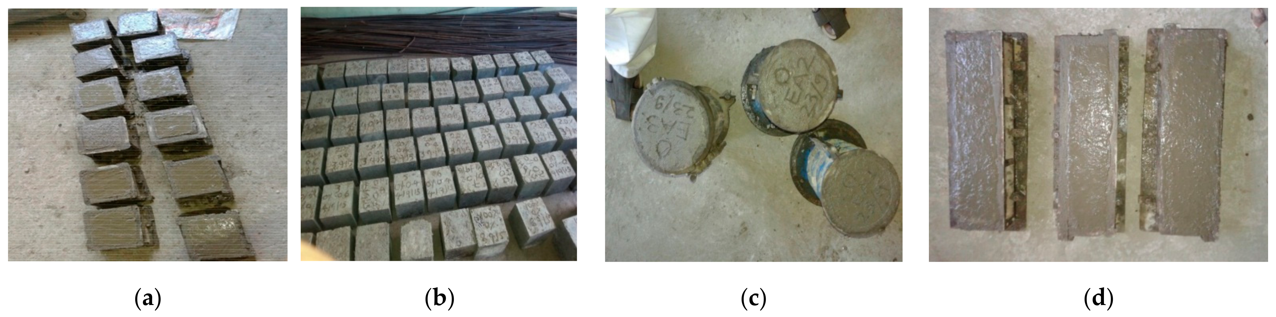
3. Experimental Procedures

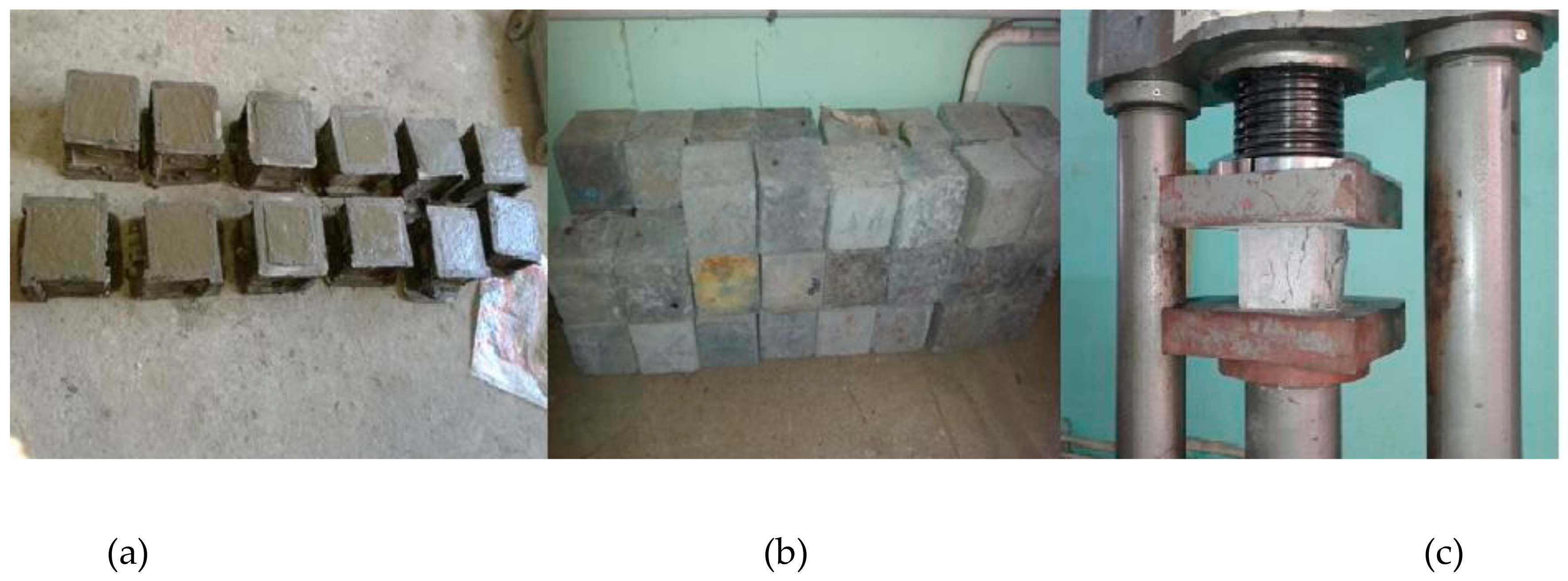
3.1. Destructive Testing

The slump and compacting tests were performed according to Indian standard IS-1199-1959 [69] to analyze the workability characteristics. The dry weight of the concrete cubes was noted to find the dry density of concrete before testing the compression test. Compressive strength tests on concrete cubes and cement mortar cubes were conducted on cubes of sizes 150 mm × 150 mm × 150 mm and 70.6 mm × 70.6 mm × 70.6 mm, respectively. A compression testing machine set at 2000 kN and 300 kN was used to conduct the compression test on concrete and mortar cubes. The test was performed according to the codal provision IS 516-1959 [70]. Figure 3 shows cast specimens for different destructive tests. The splitting tensile strength is determined at 28 days on cylinders of 150 mm in diameter and 300 mm in length, as per IS: 516-1959. Microstructural images are captured via HITACHI-3000N scanning electron microscope. Figure 4 illustrates the split tensile test using the compression testing machine (Figure 4a) and scanning electron microscope (Figure 4b). An array of electrons focused on the sample and backscattered the secondary electrons. The signals detect the secondary electrons to produce the nanoscale images.

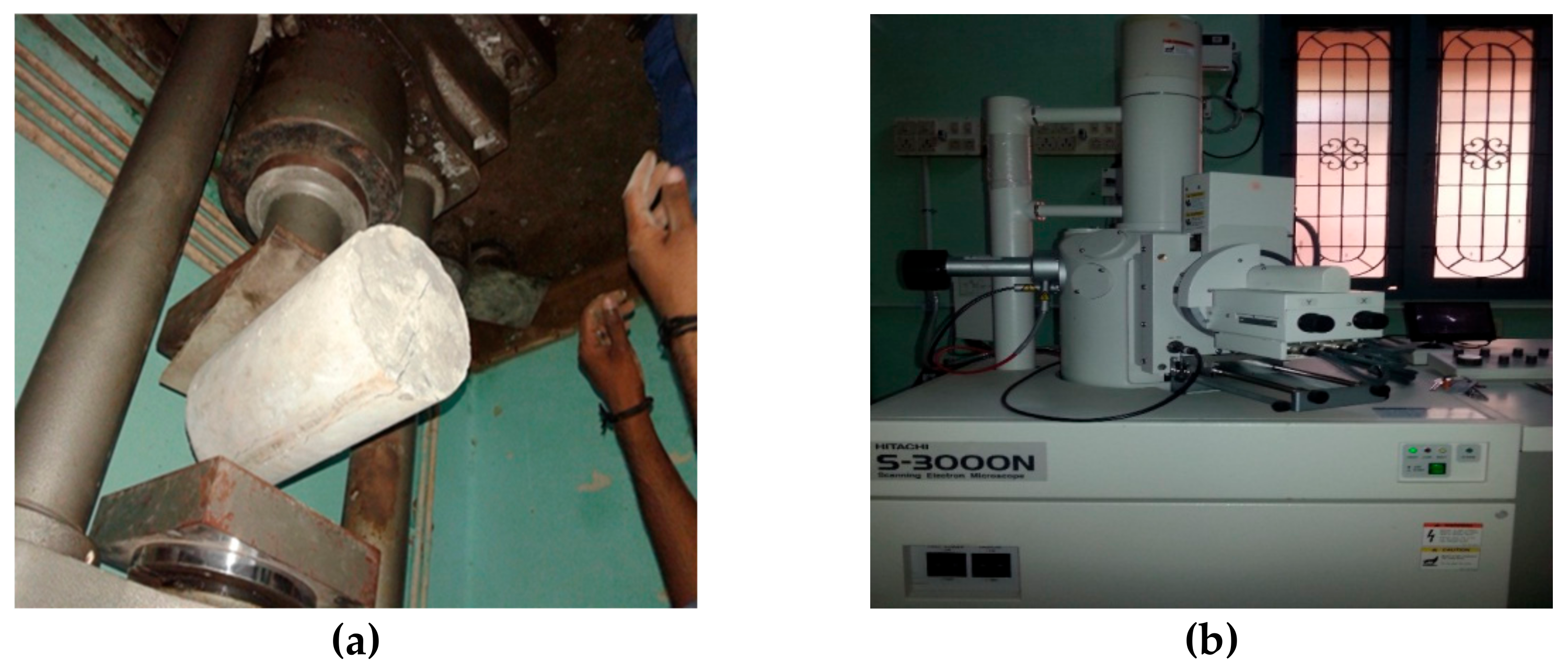
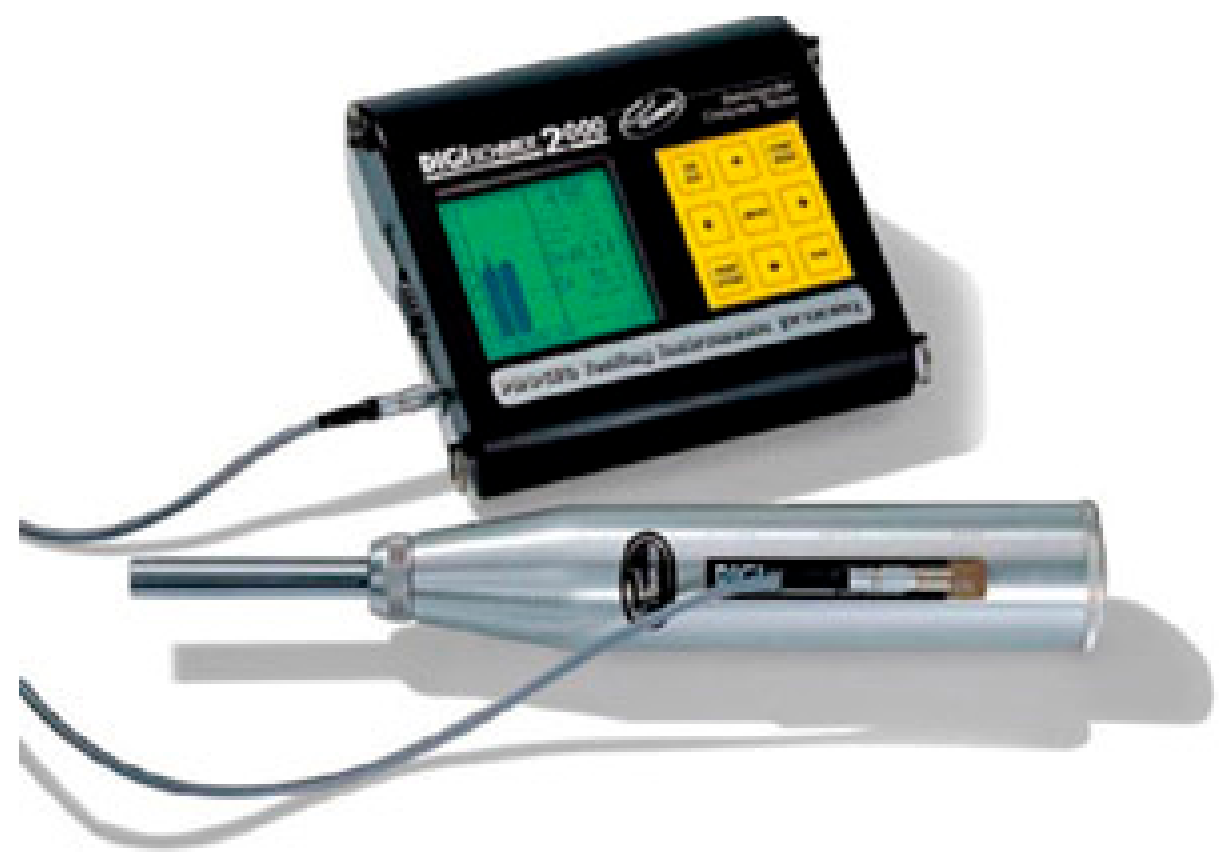
3.2. Non-Destructive Testing

3.2.1. Ultrasonic Pulse Velocity

The UPV test is an in situ, qualitative, non-destructive testing methodology for concrete conducted per the procedure in IS: 13311:1992 [71]. Before conducting destructive tests, this test was performed on 150 mm × 150 mm × 150 mm cubes. The UPV test is used to analyze the porous, cavities, and non-homogeneity of the concrete in terms of applying and receiving the electronic pulses on both sides of the concrete specimen. The velocity of electronic waves is influenced by the concrete grade, path length, curing period, and maximum size of aggregates. The instrument consists of a transducer, receiver or pulser (two probes), and necessary display units. The sound energy produced by the pulse passes through the transducer as wave energy. Some energy is back-reflected because of cavities and flaws inside the concrete. The time taken by the pulse to penetrate the structure is measured. After calibration with a standard sample material with known properties, the transducers were placed on opposite sides of the material. A portable ultrasonic non-destructive digital indicating tester (PUNDIT) was used to test UPV, as shown in Figure 5. Pulse velocity was measured by a simple formula (1):
U l t r a s o n i c   P u l s e   v e l o c i t y = P a t h   l e n g t h T r a n s i t   t i m e ,
In the case of flaws and cavities, the time taken to travel for a particular path length is high, which indicates the lower velocity of sound waves, and results in poor quality of concrete. This velocity relates to the compressive strength of concrete. Table 5 presents the pulse velocity, which relates to the quality of concrete.

3.2.2. Rebound Hammer Test

Concrete’s surface hardness is expressed as the non-destructive compressive strength of concrete. The uniformity of the concrete is affected by the compaction variability and variability in curing and temperature changes. Figure 6 illustrates the SCHMIDT rebound hammer (digital) equipment used to assess the uniformity of concrete. It was used to obtain the average compressive strength of 150 mm3 cube at 28 days. The surface was cleaned and free from moisture content. The impact load was applied at a constant energy of 2.2 Nm. The number of trails against each measurement was entered as input data before starting the test. The impact energy is used so that the hammer spring rebounds against the concrete surface. The surface hardness of concrete is indicated as the compressive strength. According to BIS 13311—Part 2 [71], the estimation can vary by ±25% with the experimental compressive strength results.

4. Results and Discussions
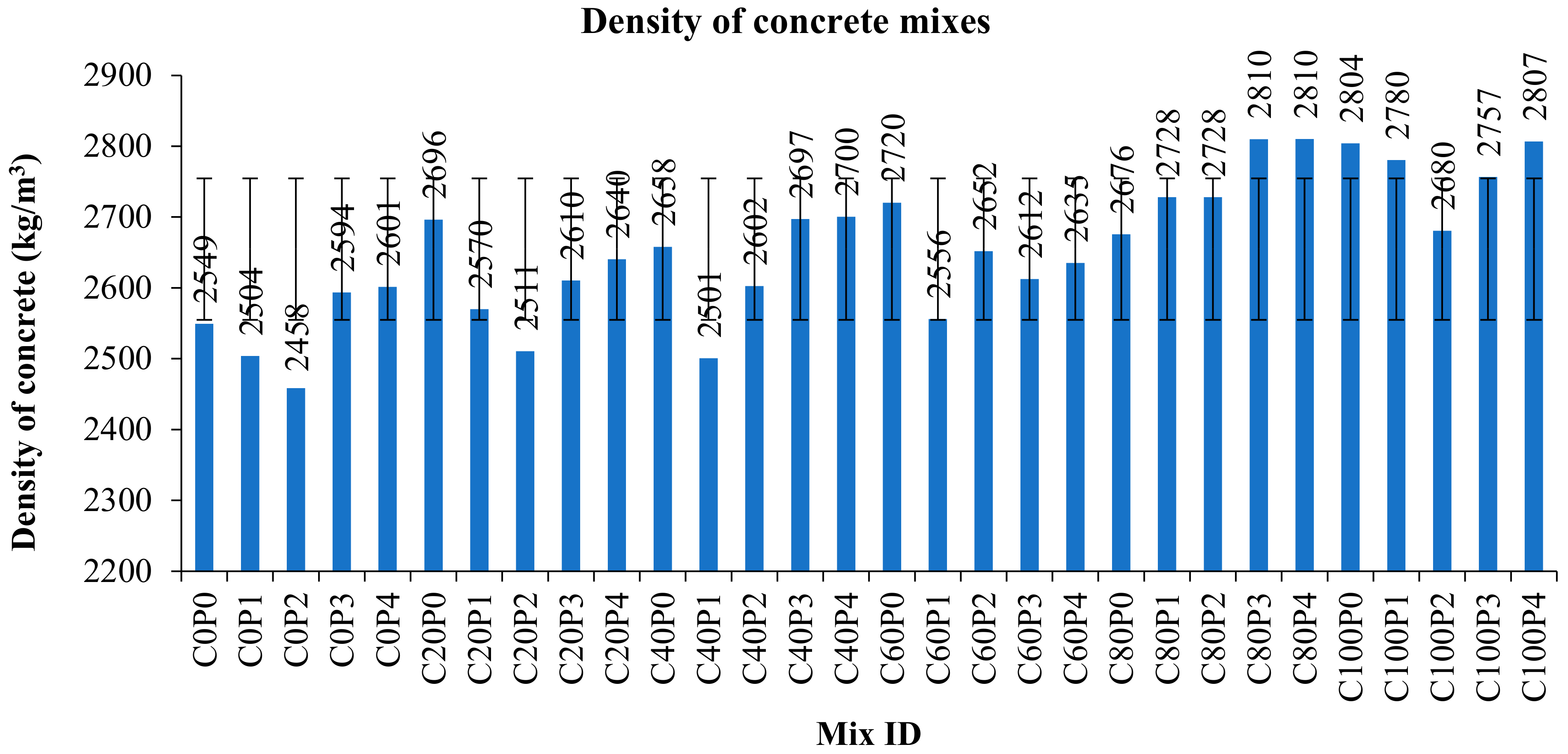
4.1. Density

Copper slag is available in the fine aggregate state, and has a higher bulk density than river sand and crushed stone aggregate. The fineness modulus lies between sand and coarse aggregate. Copper slag occupies less volume than concrete due to its higher bulk density and specific gravity. These factors invariably influence the density of concrete. Hence, concrete with copper slag has higher density values, ranging from 2500 kg/m3 to 2850 kg/m3 [72]. A significant reduction in density was noted with the increase in fiber content, since the fiber occupies a specific volume of the concrete depending upon its percentage volume fraction in the concrete. Figure 7 shows the variation in density of all mixes. The minimum density observed was 2696 kg/m3, whereas the maximum density was 2810 kg/m3. The densities varied from 5% to 10% compared to control concrete.

4.2. Workability

Figure 8 illustrates the variation in the slump and compacting factors. Many studies have proven that the copper slag has outstanding workability characteristics because of its glittering texture and low water absorption capacity [48,73,74,75]. The 100% replacement of copper slag (C100P0) has a slump value of 105 mm, whereas control concrete exhibits a 40 mm slump. One study observed that 100% copper slag shows a 200 mm slump, and the control concrete exhibited 65 mm workability. However, 100% copper slag was noted to exhibit bleeding and segregation, even with the addition of PPF [37,76]. C100P4 decreases the slump value significantly to 47 mm. Adding polypropylene fiber leads to excess water demand in the interfacial transition zone (ITZ). Loss of moisture content in ITZ causes cracking. The presence of copper slag avoids fluid loss and improves the microstructure of the cement aggregate phase. Copper slag is crystalline in structure and has a glassy appearance. The surface prevents free surface moisture from entering. As a result, accessible water is conserved for hydration, which densifies the microstructure. Additionally, the diamond length of a single fibrillated polypropylene fiber is longer; hence, the cement paste needed to coat the fiber substantially reduces the fluidity of the concrete. It is worth noting that the addition of PPF maintains the ideal slump value; the sand is entirely replaced with copper slag. The concrete containing 0.8% PPF had a large lumped mass of fibers and exhibited difficulty in mixing due to the insufficient capacity of the mortar and considerable amount of fibers, which were visible in the fresh concrete mix. It was observed that clear segregation did not occur in mixes up to 80% of copper slag substitution with PPF.
The degree of compaction was determined using a compacting factor test. The compacting factor values of copper slag–PPF concrete ranged from 0.90 to 0.95, whereas the compacting factor of control concrete was 0.942. The high specific gravity of copper slag in concrete facilitates the self-settling of aggregates, resulting in void-free concrete. Conversely, PPF added to concrete occupies a specific volume, resulting in weight loss in partially compacted concrete. Hence, there was a slight decrease in compacting factor when PPF was added to the concrete. However, this difference had no influence, since the desirable compacting factor for manually compacted heavily reinforced sections is 0.90 to 0.95. The equivalent slump values analogous to the above-mentioned compacting factors start from 50 mm to 100 mm.

4.3. Destructive Testing

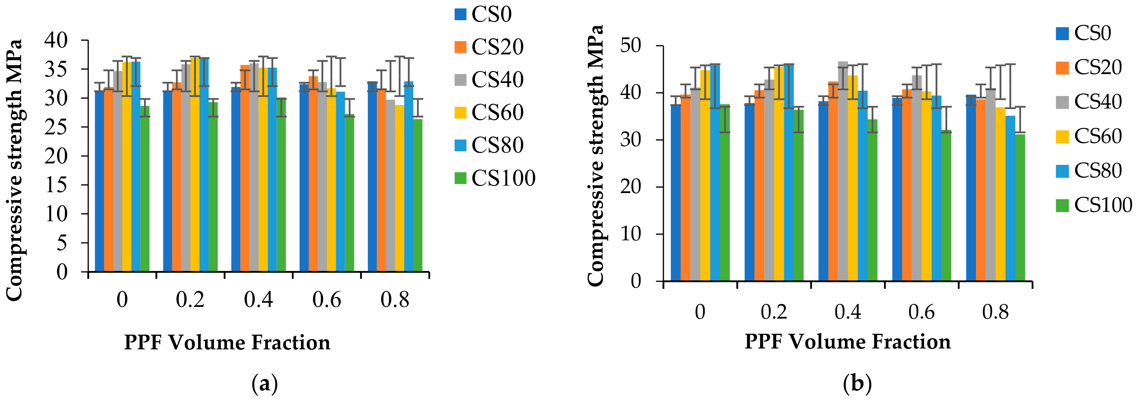
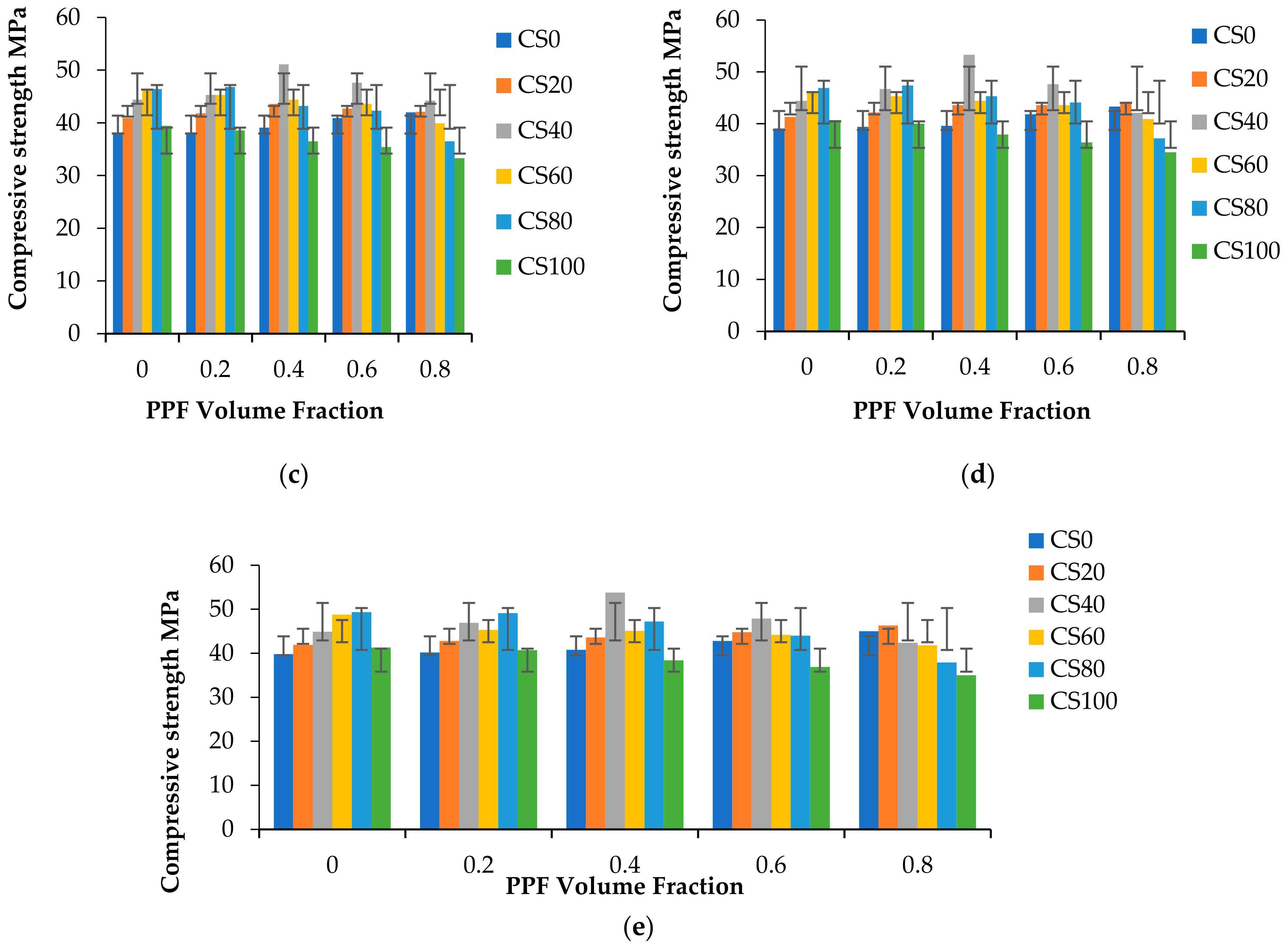
4.3.1. Compressive Strength

From Figure 4, Figure 5, Figure 6, Figure 7, Figure 8 and Figure 9 in this study, it was predicted that strength increases as the curing period increases. Past literature [45,77,78] analyzed copper slag incorporation into high-strength concrete, cement mortar, and high-performance concrete applications. The common observation in the results of these studies was that the copper slag addition increases the compressive strength over the control concrete. Most research has concluded that 30% to 40% of copper slag is the optimum replacement [38,79,80]. Some studies have confirmed that the compressive strength gradually increases up to 60%, and then decreases.
Moreover, it was found that 100% copper slag replacement does not meet the mean target strength [38,81,82]. Adding fiber contributes to the enhancement of compressive strength by 6%. Copper slag replacement of 20% delivers a 35% improvement in compressive strength at 28 days. However, Hsie et al. [61] reported only a 14.6 to 17.35 % strength gain over control concrete. Copper slag content increases the volume of free water in the concrete. PPF contributes higher water absorption characteristics in up to 40% copper slag mixes. Beyond this limit, the surplus water remains unused by the fiber matrix regarding pronounced segregation [83]. High compressive strength was observed at 40% copper slag, and PPF 0.4% exhibited a 15 to 35% increase in strength. Since particle size distribution plays a significant role, the particle packing of 40% copper slag can maintain good characteristic strength. Copper slag 40% replacement exhibits the optimum compressive strength value of 53.8 N/mm2 at 180 days. PPF 0.6% can be used with 60% copper slag to produce workable concrete. After that, compressive strength decreases as copper slag replacement increases from 60% to 100%. The decrease in the compressive strength of concrete is due to the presence of freely available water in cement, but the strength value does not fall below the target mean strength or the compressive strength of control concrete. Replacement of 80% copper slag (Figure 9) achieved the highest strength (50.3 N/mm2) at 180 days without fiber content. The 100% replacement of copper slag to fine aggregate exhibited higher strength than control concrete.

4.3.2. Compressive Strength of Cement Mortar

Compressive strength results were obtained by casting and testing cement mortar cubes of size 70.6 mm × 70.6 mm × 70.6 mm at 7 and 28 days. In addition, various proportions of copper slag and polypropylene fiber constituting 180 specimens were tested; the results are tabulated in Table 6, followed by the graphical representation in Figure 10. Additionally, Figure 11 shows the sample of specimens involved in casting (Figure 11a), curing (Figure 11b) and testing (Figure 11c).
After 7 days, the C100P2 mix shows 44% higher compressive strength. Even when the sand was 100% replaced with copper slag, it showed 11% higher compressive strength than control concrete. Compared to control concrete, the C20P2 mortar mix exhibited a 133.31% increase in compressive strength after 7 days. This was due to the confinement of the mortar mix due to the PPF in the concrete.
The compressive strengths of cement mortar at 28 days for C20P0 mix and C80P2 mix were 39.11 N/mm2 and 37.33 N/mm2, respectively. This implies that the replacement of 20% and 80% copper slag produces 83% and 75% higher strength values than the reference mix. Copper slag replacement without PPF increased compressive strength by 11.13%, whereas the addition of PPF further improved the compressive strength by 25.57%. By no means did the compressive strength of any of the mixes fall below that of the control mix. Hence, the copper slag can be entirely replaced with sand in cement mortar application to maximize waste utilization. Table 7 illustrates the splitting and tensile strength of concrete. The ratio between splitting tensile strength and compressive strength indicates that the compressive strength is closely related to tensile stress.

4.4. Non-Destructive Testing

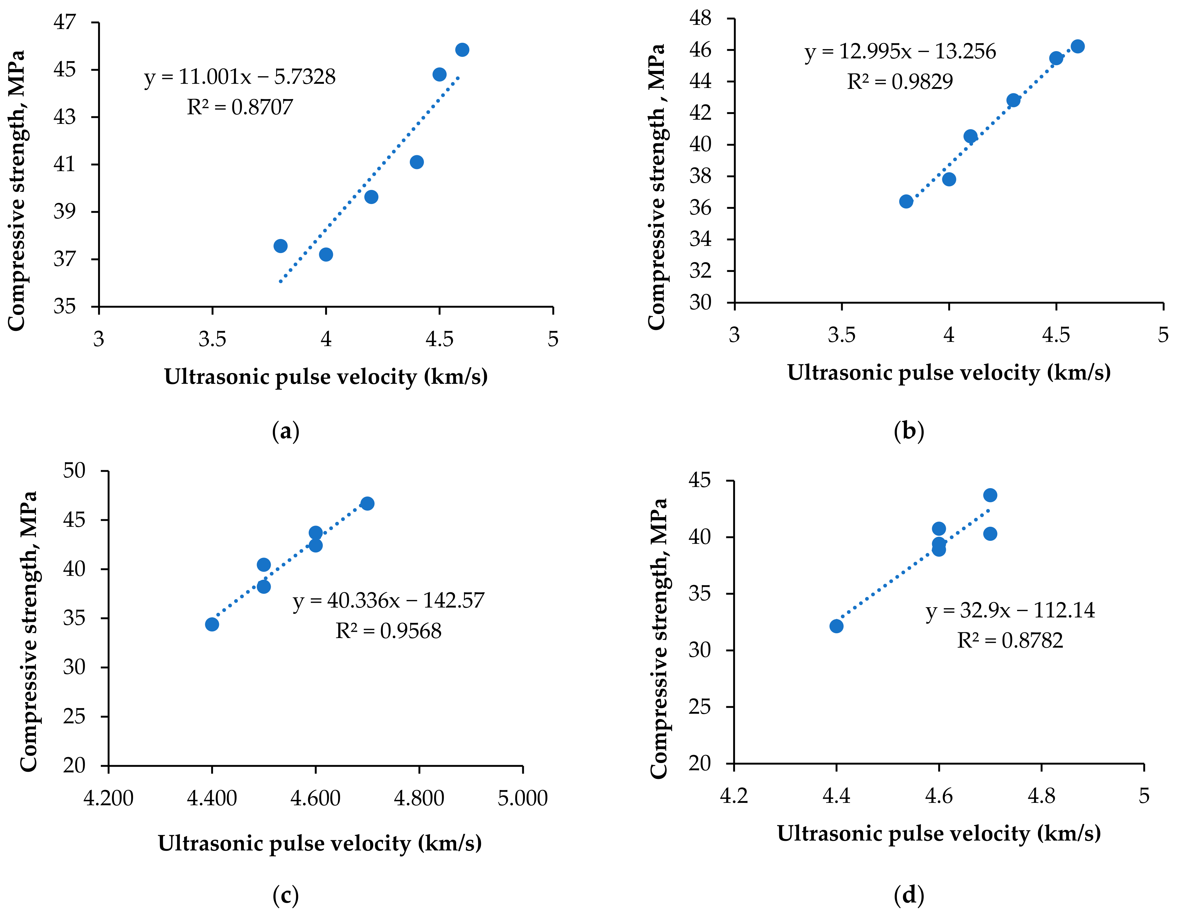
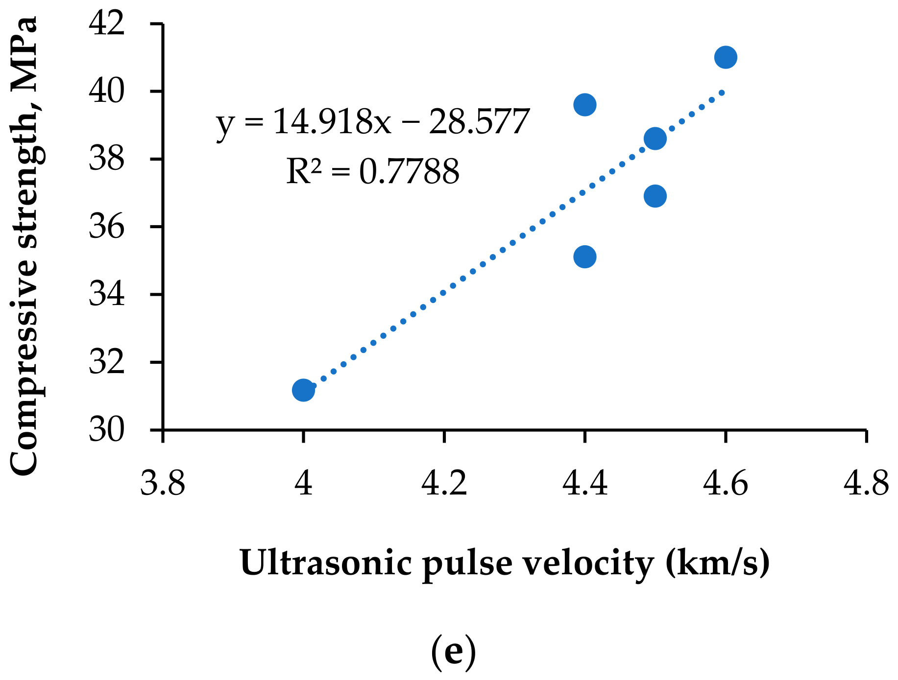
4.4.1. Ultrasonic Pulse Velocity

The transit time in µs was noted for each cube specimen at 28 days of curing. The ultrasonic pulse velocity was calculated as per the formula in Equation (1). Table 8 lists the ultrasonic pulse velocity and rebound hammer values. The pulse velocity increased to 0.6% fiber volume fraction and increased further to 0.8%. In that volume fraction, if copper slag is in lower quantity, it causes a balling effect and reduces the homogeneity and the performance of the concrete [84]. At higher volumes of copper slag content, 0.8% of PPF produces large amounts of bleeding and segregation. The fibers become clogged in separate places, leading to microcrack propagation in the concrete matrix [85]. This is the reason for the voids and non-homogenous structure of the cement concrete matrix, which delays the transit [86]. At the same time, increase in pulse velocity up to 0.6% PPF contributes to the networking texture of the PPF composite of the cement concrete matrix, and the bridging mechanism of PPF with copper slag concrete matrix. The larger the substitution, the greater the free water available. If the water–cement ratio increases, the pulse velocity decreases due to the availability of large capillary pores and microscale cracks inside the concrete [87]. Ultrasonic waves pass faster when the cement concrete matrix is filled with water than air [53]. The highest pulse velocities obtained for each replacement of copper slags were as follows: C0P3, 4700 m/s; C20P2 and C20P3, 4600 m/s; C40P2 and C40P3, 4700 m/s; C60P3, 4700 m/s; C80P3, 4600 m/s; and C100P3, 4400 m/s. The lowest pulse velocity values were obtained at 100% replacement of copper slag. Even the quality of the concrete was ascertained to be as good as the codal provisions. Figure 12 depicts the prediction of compressive strength over UPV values.
Following Equations (2) to (4) are the compressive strength equations using UPV obtained by the previous researchers. Equations (5) and (6) are the equations derived in this study. fc is the predicted compressive strength of concrete [88,89].
fc’ = 20.312UPV − 40.959
fc’ = 0.0171UPV − 25.478
fc’ = 0.1982UPV3.79
fc’ = 12.995UPV − 13.256
fc’ = 40.336UPV − 142.57

4.4.2. Rebound Hammer

A rebound hammer expresses the relationship between the surface hardness and the compressive strength of concrete within the limiting error. Rebound hammer observations are discarded when the variation is more than 15%. Three continuous impacts were applied perpendicular to the reference plane. Figure 13 presents the compressive strength values obtained using the rebound number. The rebound number increases as the surface resistance increases. The high specific gravity of copper slag offers more resistance to the surface indentation. CS100% shows less resistance to the hammering force. The maximum compressive strength was observed as 37.6 MPa at the C40P2 proportion. The minimum compressive strength was noted to be 20.2 MPa at the C100P3 mix. In total, 13% of results fell below 30 MPa, and all others were between 30 to 40 MPa. Except 100% copper slag replacement, all of the different mixes showed excellent resistance as per the codal provision IS 1881-Part 2 (1986) [90]. It is observed that the CS40 series showed good resistance for the surface indentation. It is concluded that the 60:40 ratio of copper slag versus sand performed well in Schmid Rebound hammer testing. The variability in our results may be connected to the curing condition and homogeneity. In copper slag–PPF concrete, the homogeneity was affected with 0.8% PPF, due to the large fiber volume. Regression equations were predicted to assess the compressive strength of concrete from the rebound hammer values. The equations are as indicated in Figure 13a–e, and the R2 values are nearer to 1; hence, values derived from the proposed equations fit well with the actual values.

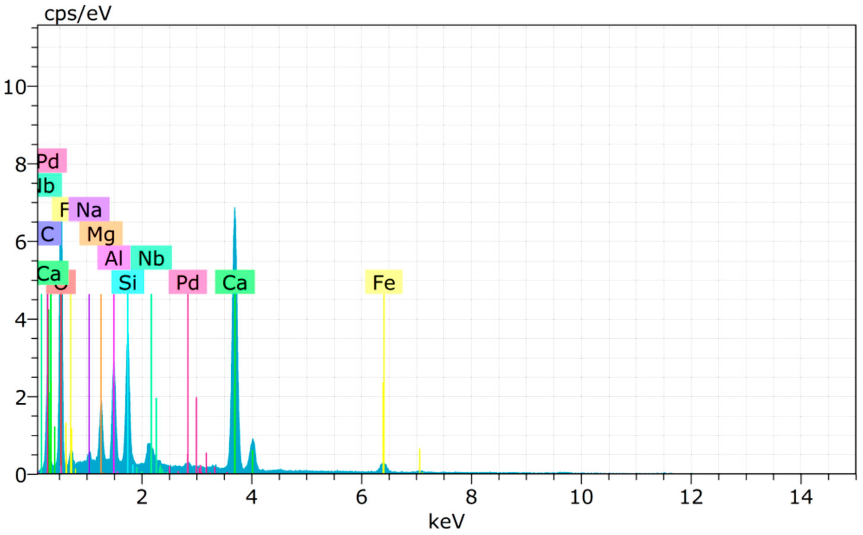
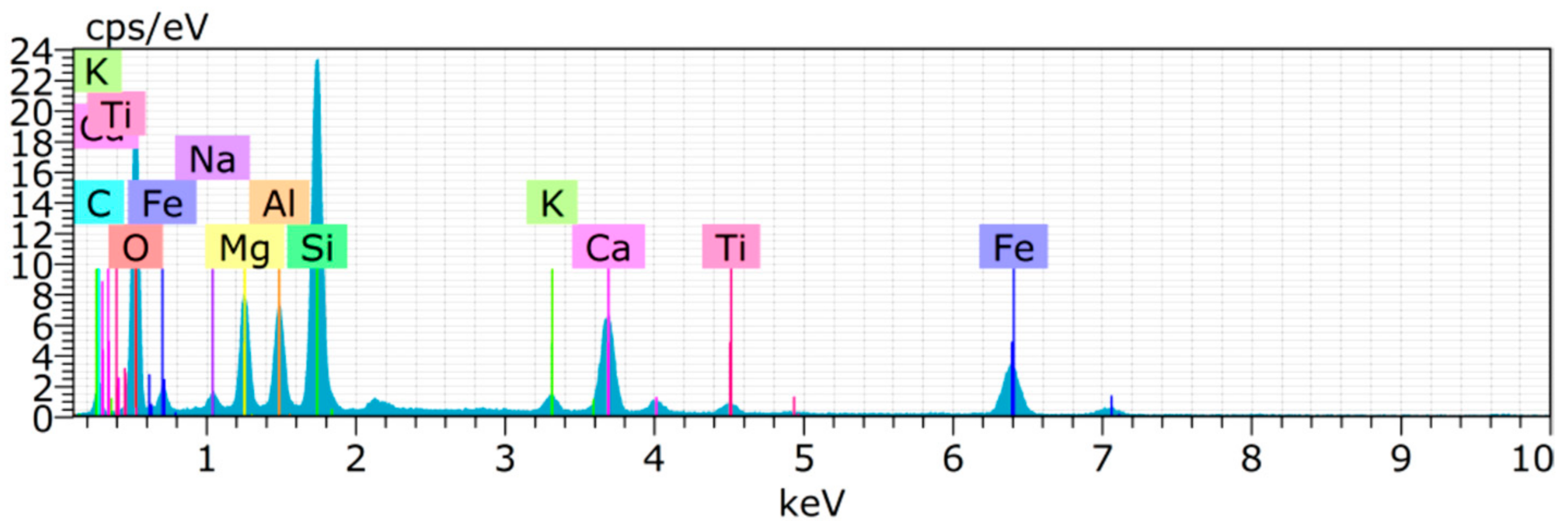
4.5. Chemical Composition of Copper Slag

The main components in cement and copper slag are shown in Figure 14 and Figure 15. The chemical compositions of the materials are compared in Table 3. The main components in copper slag are Fe2O3 and SiO2 [91]. Since the amount of calcium oxide in copper slag is relatively low, it produces a pozzolanic effect rather than exhibiting cementitious properties. Similar compounds were found in cement and copper slag, such as Ca, Si, Al, Na, Fe, Mg, etc. The high peaks from the XRD image of copper slag indicate the presence of iron silicate fines and magnetite in the crystalline form [92]. Aluminum compounds in copper slag combine with dehydrated calcium hydroxide to produce a calcium aluminate hydrate with cementitious properties [72]. Hence, it improves the dense microstructure and strength characteristics of concrete.
Significant explanations were proposed regarding the SEM images of the cement aggregate matrix of the control concrete and copper slag-replaced concrete. Control concrete (Figure 16a) showed very little C–S–H gel, whereas the C20 mix (Figure 16b) showed C–S–H gel formation due to the additional silicate ions contributed by CS. In successive replacement mixes, it was evident that the presence of C–S–H gel was greater. The substitution exceeding 60% was shown with capillary pores and separation of PPF due to excess water in the concrete. C40 (Figure 16c) and C60 (Figure 16d) were identified with PPF surrounded by C–S–H gel, which was missing in the C80 (Figure 16e) proportion. The microcracks, voids, and capillary pores combined to form the networking fracture fault zones, leading to premature failure of the specimen under its service condition. At higher copper slag levels, the smooth, heavy, and glassy surface texture of copper slag induced the water to bleed to the top of the concrete, producing the weakest links in the microstructure, with available pores, voids, and microcracks [93]. In the C100 mix (Figure 16f), the PPF was not frequently observed in the microstructure images, even in 0.8% PPF. Due to lower density of PPF, it floats at the top because of excess bleeding in 100% replacement of copper slags. Since copper slag exhibits medium pozzolanic behavior, the presence of CA(Oh)2 is unavoidable in each mix proportion. We conclude that C–S–H gel formation increases as the replacement increases up to 60%, and further reduces due to excess water. Eventually, the strength decreases below the target level.

5. Conclusions

This paper extends the comparative study of copper slag concrete with polypropylene fiber (PPF) subjected to destructive and non-destructive testing. Under destructive testing of compressive strength of concrete cubes, compressive strength of mortar cubes, splitting tensile test on cylindrical specimens, and flexural tests on plain cement concrete were conducted and analyzed. Ultrasonic pulse velocity and rebound hammer tests were performed as per IS13311-Part 1-1992 for non-destructive testing. In addition, this experimental work also analyzed the microstructure of the concrete and its mechanical properties through destructive, as well as non-destructive testing. The derived conclusions are listed as follows:
-
Copper slag has sharp angular lines and points that bond between aggregates. It has dimensional stability due to its high density. The density of the concrete increased within the range of 5% to 10%.
-
In line with the IS: 383-1970, the gradation of 40% of copper slag replaced with sand fits with zone II. Copper slag 20%, 60%, 80%, and 100% replacements satisfy zone I criterion, which shows that the particle sizes are coarser than sand.
-
Fiber-reinforced concrete alone gives equivalent or lower strength when compared to the control. From our results, copper slag addition leads to a 35% increase in the compressive strength of concrete. The application of copper slag for mortar shows better results, up to 80% replacement. Compressive strength increased to 75% was reported against the reference mix.
-
The split tensile test of concrete disclosed that the maximum split tensile strength of 3.54 N/mm2 was perceived at the C40P4 mix, which was 31.58% greater than the control concrete. The maximum flexural strength of control concrete at 28 days for the C40P2 mix was 9.58 N/mm2, which is a 26.05% increase compared to control concrete.
-
In cement mortar, the maximum compressive strength at 28 days was 39.11 N/mm2 for 20% copper slag and 0.4% PPF, which was 83% higher than normal concrete.
-
Even 80% copper slag in cement mortar produced a compressive strength of 37.11 N/mm2 at 28 days, which was almost 75% greater than the compressive strength of the control mix.
-
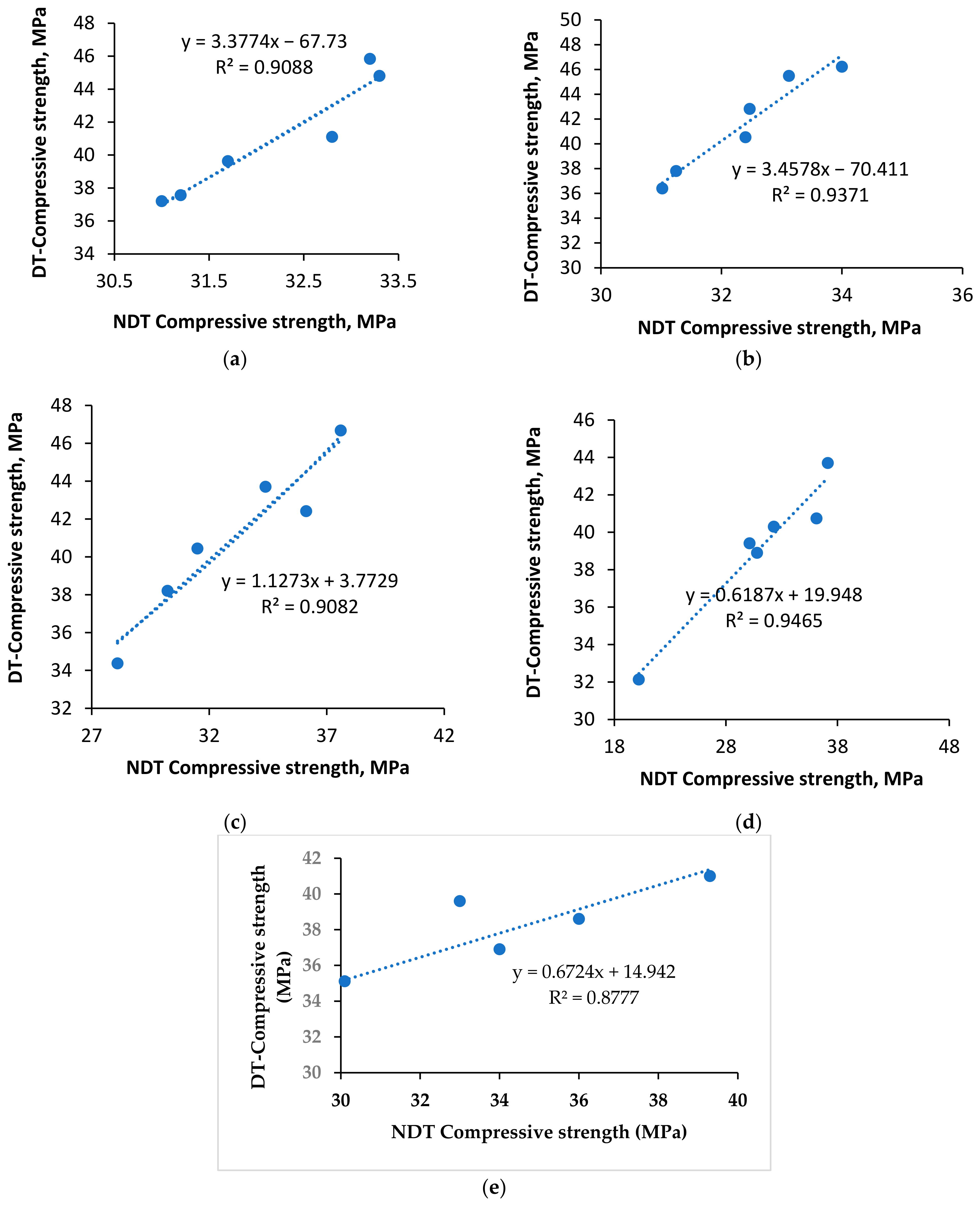
The concrete quality is good, and, in fact, excellent according to the ultrasonic pulse velocity test. In the rebound hammer test, 87% of results showed 30 to 40 MPa strength values, while only 13% fell below 30 MPa. The regression analysis designed to predict the compressive strength through NDT testing provided a better fit with the true values.
-
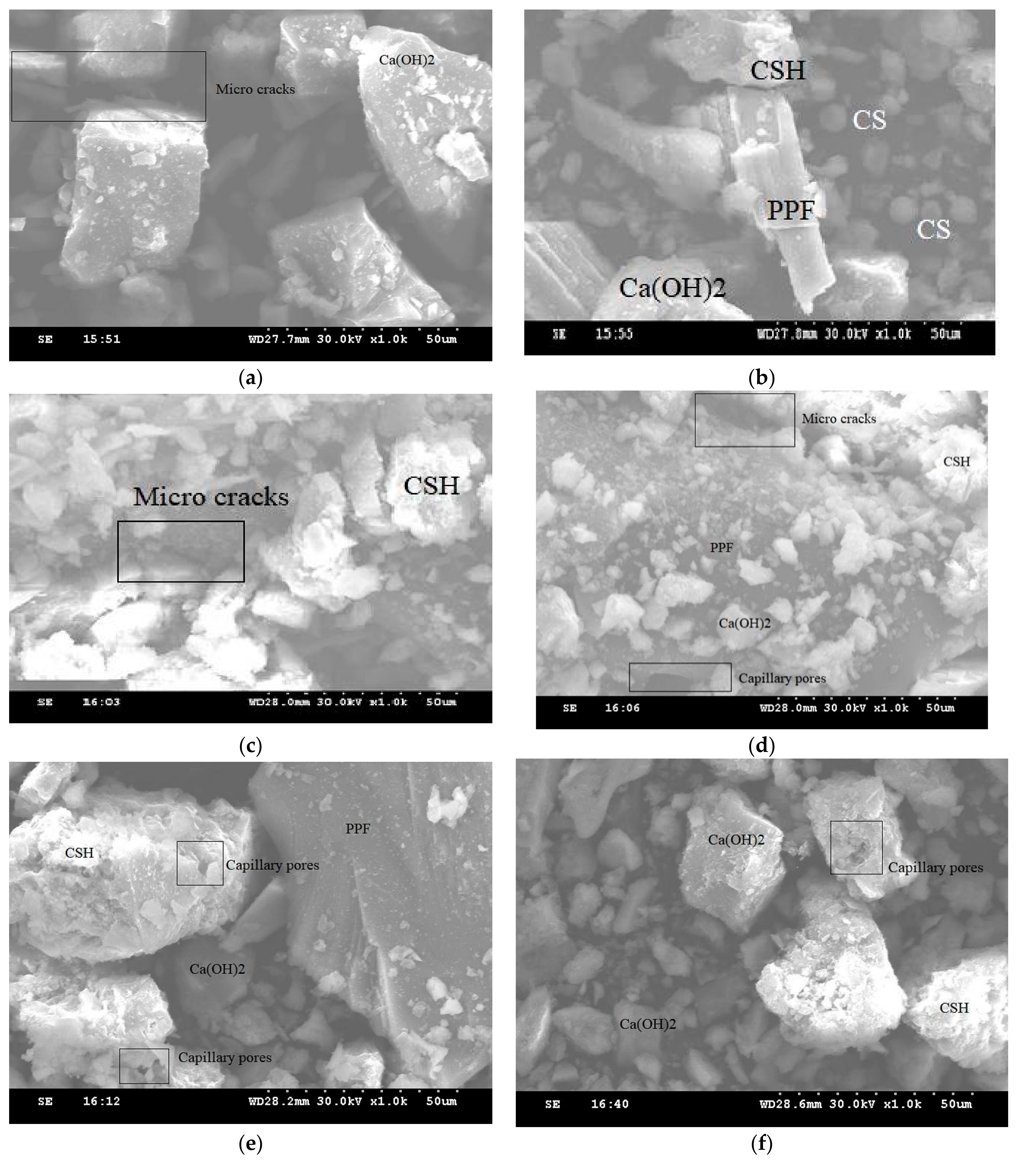
The Ca(OH)2 crystalline structure freely available in the microstructure of control concrete is depleted in copper slag concrete, since the copper slag consumes the unreacted Ca(OH)2 to produce C–S–H gel.

Author Contributions

Conceptualization, V.C. and B.D.; Data curation, V.C., B.D., S.A., M.A., E.S.F., M.A.A., R.F., N.I.V. and R.S.M.R.; Formal analysis, V.C., B.D., S.A., M.A., E.S.F., M.A.A., R.F., N.I.V. and R.S.M.R.; Funding acquisition, M.A., R.F. and N.I.V.; Investigation, V.C. and B.D.; Methodology, V.C., B.D. and S.A.; Project administration, B.D.; Resources, B.D., S.A., M.A., R.F. and N.I.V.; Software, V.C.; Supervision, B.D. and S.A.; Validation, B.D., S.A., M.A., E.S.F., M.A.A., R.F., N.I.V. and R.S.M.R.; Visualization, M.A., E.S.F., M.A.A., R.F., N.I.V. and R.S.M.R.; Writing—original draft, V.C.; Writing—review & editing, B.D., S.A., M.A., E.S.F., M.A.A., R.F., N.I.V. and R.S.M.R. All authors have read and agreed to the published version of the manuscript.

Funding

The research is partially funded by the Ministry of Science and Higher Education of the Russian Federation as part of the World-class Research Center program: Advanced Digital Technologies (contract No. 075-15-2022-311 dated 20 April 2022).

Institutional Review Board Statement

Not applicable.

Informed Consent Statement

Not applicable.

Data Availability Statement

Data sharing not applicable.

Acknowledgments

The authors gratefully appreciate the support for the experimental works given by the Department of Civil Engineering, Alagappa Chettiar Government College of Engineering and Technology, Karaikudi, Tamilnadu, India. E.I. Saavedra Flores acknowledges the financial support from the Chilean National Agency for Research and Development (ANID), research grant FONDECYT REGULAR No. 1211767. Also, the authors gratefully acknowledge the financial support given by the Deanship of Scientific Research at Prince Sattam bin Abdulaziz University, Alkharj, Saudi Arabia, for this research.

Conflicts of Interest

The authors declare no conflict of interest.

Correction Statement

This article has been republished with a minor correction to resolve spelling and grammatical errors. This change does not affect the scientific content of the article.

References

  1. Amran, M.; Murali, G.; Khalid, N.H.A.; Fediuk, R.; Ozbakkaloglu, T.; Lee, Y.H.; Haruna, S.; Lee, Y.Y. Slag uses in making an ecofriendly and sustainable concrete: A review. Constr. Build. Mater. 2021, 272, 121942. [Google Scholar] [CrossRef]
  2. Fediuk, R.; Amran, M.; Vatin, N.; Vasilev, Y.; Lesovik, V.; Ozbakkaloglu, T. Acoustic properties of innovative concretes: A review. Materials 2021, 14, 398. [Google Scholar] [CrossRef] [PubMed]
  3. Gagg, C.R. Cement and concrete as an engineering material: An historic appraisal and case study analysis. Eng. Fail. Anal. 2014, 40, 114–140. [Google Scholar] [CrossRef]
  4. Mundra, S.; Sindhi, P.R.; Chandwani, V.; Nagar, R.; Agrawal, V. Crushed rock sand—An economical and ecological alternative to natural sand to optimize concrete mix. Perspect. Sci. 2016, 8, 345–347. [Google Scholar] [CrossRef]
  5. Kumar, P.; Singh, N. Influence of recycled concrete aggregates and coal bottom ash on various properties of high volume fly ash-self compacting concrete. J. Build. Eng. 2020, 32, 101491. [Google Scholar] [CrossRef]
  6. Aggarwal, Y.; Siddique, R. Microstructure and properties of concrete using bottom ash and waste foundry sand as partial replacement of fine aggregates. Constr. Build. Mater. 2014, 54, 210–223. [Google Scholar] [CrossRef]
  7. Amran, M.; Fediuk, R.; Murali, G.; Avudaiappan, S.; Ozbakkaloglu, T.; Vatin, N.; Karelina, M.; Klyuev, S.; Gholampour, A. Fly ash-based eco-efficient concretes: A comprehensive review of the short-term properties. Materials 2021, 14, 4264. [Google Scholar] [CrossRef]
  8. Amran, M.; Debbarma, S.; Ozbakkaloglu, T. Fly ash-based eco-friendly geopolymer concrete: A critical review of the long-term durability properties. Constr. Build. Mater. 2021, 270, 121857. [Google Scholar] [CrossRef]
  9. Amran, M.; Lee, Y.H.; Fediuk, R.; Murali, G.; Mosaberpanah, M.A.; Ozbakkaloglu, T.; Lee, Y.Y.; Vatin, N.; Klyuev, S.; Karelia, M. Palm oil fuel ash-based eco-friendly concrete composite: A critical review of the long-term properties. Materials 2021, 14, 7074. [Google Scholar] [CrossRef]
  10. Amran, M.; Murali, G.; Fediuk, R.; Vatin, N.; Vasilev, Y.; Abdelgader, H. Palm oil fuel ash-based eco-efficient concrete: A critical review of the short-term properties. Materials 2021, 14, 332. [Google Scholar] [CrossRef]
  11. Makul, N.; Fediuk, R.; Amran, M.; Zeyad, A.M.; Murali, G.; Vatin, N.; Klyuev, S.; Ozbakkaloglu, T.; Vasilev, Y. Use of recycled concrete aggregates in production of green cement-based concrete composites: A review. Crystals 2021, 11, 232. [Google Scholar] [CrossRef]
  12. Tolstoy, A.; Lesovik, V.; Fediuk, R.; Amran, M.; Gunasekaran, M.; Vatin, N.; Vasilev, Y. Production of greener high-strength concrete using russian quartz sandstone mine waste aggregates. Materials 2020, 13, 5575. [Google Scholar] [CrossRef]
  13. Makul, N.; Fediuk, R.; Amran, M.; Zeyad, A.M.; Klyuev, S.; Chulkova, I.; Ozbakkaloglu, T.; Vatin, N.; Karelina, M.; Azevedo, A. Design strategy for recycled aggregate concrete: A review of status and future perspectives. Crystals 2021, 11, 695. [Google Scholar] [CrossRef]
  14. Makul, N.; Fediuk, R.; Amran, H.M.M.; Zeyad, A.M.; de Azevedo, A.R.G.; Klyuev, S.; Vatin, N.; Karelina, M. Capacity to develop recycled aggregate concrete in South East Asia. Buildings 2021, 11, 234. [Google Scholar] [CrossRef]
  15. Patel, D.; Shrivastava, R.; Tiwari, R.P.; Yadav, R.K. Properties of cement mortar in substitution with waste fine glass powder and environmental impact study. J. Build. Eng. 2020, 27, 100940. [Google Scholar] [CrossRef]
  16. Dai, J.; Wang, Q.; Xie, C.; Xue, Y.; Duan, Y.; Cui, X. The effect of fineness on the hydration activity index of ground granulated blast furnace slag. Materials 2019, 12, 2984. [Google Scholar] [CrossRef]
  17. Aprianti, E.; Shafigh, P.; Bahri, S.; Farahani, J.N. Supplementary cementitious materials origin from agricultural wastes—A review. Constr. Build. Mater. 2015, 74, 176–187. [Google Scholar] [CrossRef]
  18. Amran, Y.H.M.; Alyousef, R.; Alabduljabbar, H.; El-Zeadani, M. Clean production and properties of geopolymer concrete; A review. J. Clean. Prod. 2020, 251, 119679. [Google Scholar] [CrossRef]
  19. Wang, W.; Noguchi, T. Alkali-silica reaction (ASR) in the alkali-activated cement (AAC) system: A state-of-the-art review. Constr. Build. Mater. 2020, 252, 119105. [Google Scholar] [CrossRef]
  20. Samad, S.; Shah, A. Role of binary cement including supplementary cementitious material (SCM), in production of environmentally sustainable concrete: A critical review. Int. J. Sustain. Built Environ. 2017, 6, 663–674. [Google Scholar] [CrossRef]
  21. Yang, K.H.; Song, J.K.; Song, K.I. CO2 reduction assessment of alkali-activated concrete based on korean life-cycle inventory database. In Handbook of Low Carbon Concrete; Butterworth-Heinemann: Oxford, UK, 2017; pp. 139–157. [Google Scholar] [CrossRef]
  22. Tavasoli, S.; Nili, M.; Serpoosh, B. Effect of GGBS on the frost resistance of self-consolidating concrete. Constr. Build. Mater. 2018, 165, 717–722. [Google Scholar] [CrossRef]
  23. Mathew, B.J.; Sudhakar, M.; Natarajan, C. Strength, economic and sustainability characteristics of coal ash—GGBS based geopolymer concrete. Int. J. Comput. Eng. Res. 2013, 3, 207–212. [Google Scholar]
  24. Liu, S.; Li, L. Influence of fineness on the cementitious properties of steel slag. J. Therm. Anal. Calorim. 2014, 117, 629–634. [Google Scholar] [CrossRef]
  25. Mengxiao, S.; Qiang, W.; Zhikai, Z. Comparison of the properties between high-volume fly ash concrete and high-volume steel slag concrete under temperature matching curing condition. Constr. Build. Mater. 2015, 98, 649–655. [Google Scholar] [CrossRef]
  26. Onn, C.C.; Mo, K.H.; Radwan, M.K.H.; Liew, W.H.; Ng, C.G.; Yusoff, S. Strength, carbon footprint and cost considerations of mortar blends with high volume ground granulated blast furnace slag. Sustainability 2019, 11, 7194. [Google Scholar] [CrossRef]
  27. Siddique, R.; Bennacer, R. Use of iron and steel industry by-product (GGBS) in cement paste and mortar. Resour. Conserv. Recycl. 2012, 69, 29–34. [Google Scholar] [CrossRef]
  28. Wang, Q.; Yan, P. Hydration properties of basic oxygen furnace steel slag. Constr. Build. Mater. 2010, 24, 1134–1140. [Google Scholar] [CrossRef]
  29. Li, J.; Yu, Q.; Wei, J.; Zhang, T. Structural characteristics and hydration kinetics of modified steel slag. Cem. Concr. Res. 2011, 41, 324–329. [Google Scholar] [CrossRef]
  30. Hu, J. Comparison between the effects of superfine steel slag and superfine phosphorus slag on the long-term performances and durability of concrete. J. Therm. Anal. Calorim. 2017, 128, 1251–1263. [Google Scholar] [CrossRef]
  31. Zhang, T.; Yu, Q.; Wei, J.; Li, J. Investigation on mechanical properties, durability and micro-structural development of steel slag blended cements. J. Therm. Anal. Calorim. 2012, 110, 633–639. [Google Scholar] [CrossRef]
  32. Wang, Q.; Yan, P.; Mi, G. Effect of blended steel slag-GBFS mineral admixture on hydration and strength of cement. Constr. Build. Mater. 2012, 35, 8–14. [Google Scholar] [CrossRef]
  33. Zhao, J.; Wang, D.; Yan, P. Design and experimental study of a ternary blended cement containing high volume steel slag and blast-furnace slag based on fuller distribution model. Constr. Build. Mater. 2017, 140, 248–256. [Google Scholar] [CrossRef]
  34. Atahan, H.N.; Dikme, D. Use of mineral admixtures for enhanced resistance against sulfate attack. Constr. Build. Mater. 2011, 25, 3450–3457. [Google Scholar] [CrossRef]
  35. Attari, A.; McNally, C.; Richardson, M.G. A COMBINED SEM—Calorimetric approach for assessing hydration and porosity development in GGBS concrete. Cem. Concr. Compos. 2016, 68, 46–56. [Google Scholar] [CrossRef]
  36. Smirnova, O.M.; Potyomkin, D.A. Influence of ground granulated blast furnace slag properties on the superplasticizers effect. Int. J. Civ. Eng. Technol. 2018, 9, 874–880. [Google Scholar]
  37. Hong, C.W.; Lee, J.I.; Ryu, J.H. Effect of copper slag as a fine aggregate on the properties of concrete. J. Ceram. Process. Res. 2017, 18, 324–328. [Google Scholar]
  38. Tang, Y.X.; Lee, Y.H.; Amran, M.; Fediuk, R.; Vatin, N.; Kueh, A.B.H.; Lee, Y.Y. Artificial Neural Network-Forecasted Compression Strength of Alkaline-Activated Slag Concretes. Sustainability 2022, 14, 5214. [Google Scholar] [CrossRef]
  39. Chin, W.Q.; Lee, Y.H.; Amran, M.; Fediuk, R.; Vatin, N.; Kueh, A.B.H.; Lee, Y.Y. A sustainable reuse of agro-industrial wastes into green cement bricks. Materials 2022, 15, 1713. [Google Scholar] [CrossRef]
  40. Lee, J.Y.; Choi, J.S.; Yuan, T.F.; Yoon, Y.S.; Mitchell, D. Comparing properties of concrete containing electric arc furnace slag and granulated blast furnace slag. Materials 2019, 12, 1371. [Google Scholar] [CrossRef]
  41. Bostanci, S.C. Use of waste marble dust and recycled glass for sustainable concrete production. J. Clean. Prod. 2020, 251, 119785. [Google Scholar] [CrossRef]
  42. Amran, M.; Al-Fakih, A.; Chu, S.H.; Fediuk, R.; Haruna, S.; Azevedo, A.; Vatin, N. Long-term durability properties of geopolymer concrete: An in-depth review. Case Stud. Constr. Mater. 2021, 15, e00661. [Google Scholar] [CrossRef]
  43. Siddika, A.; Amin, M.R.; Rayhan, M.A.; Islam, M.S.; Al Mamun, M.A.; Alyousef, R.; Mugahed Amran, Y.H. Performance of sustainable green concrete incorporated with fly ash, rice husk ash, and stone dust. Acta Polytech. 2021, 61, 279–291. [Google Scholar] [CrossRef]
  44. Chithra, S.; Senthil Kumar, S.R.R.; Chinnaraju, K. The effect of colloidal nano-silica on workability, mechanical and durability properties of high performance concrete with copper slag as partial fine aggregate. Constr. Build. Mater. 2016, 113, 794–804. [Google Scholar] [CrossRef]
  45. Al-Jabri, K.S.; Hisada, M.; Al-Oraimi, S.K.; Al-Saidy, A.H. Copper slag as sand replacement for high performance concrete. Cem. Concr. Compos. 2009, 31, 483–488. [Google Scholar] [CrossRef]
  46. Mavroulidou, M. Mechanical properties and durability of concrete with water cooled copper slag aggregate. Waste Biomass Valoriz. 2017, 8, 1841–1854. [Google Scholar] [CrossRef]
  47. Al-Jabri, K.S.; Hisada, M.; Al-Saidy, A.H.; Al-Oraimi, S.K. Performance of high strength concrete made with copper slag as a fine aggregate. Constr. Build. Mater. 2009, 23, 2132–2140. [Google Scholar] [CrossRef]
  48. Ambily, P.S.; Umarani, C.; Ravisankar, K.; Prem, P.R.; Bharatkumar, B.H.; Iyer, N.R. Studies on ultra high performance concrete incorporating copper slag as fine aggregate. Constr. Build. Mater. 2015, 77, 233–240. [Google Scholar] [CrossRef]
  49. Siddique, S.; Chaudhary, S.; Shrivastava, S.; Gupta, T. Sustainable utilisation of ceramic waste in concrete: Exposure to adverse conditions. J. Clean. Prod. 2019, 210, 246–255. [Google Scholar] [CrossRef]
  50. Kim, H.K. Utilization of sieved and ground coal bottom ash powders as a coarse binder in high-strength mortar to improve workability. Constr. Build. Mater. 2015, 91, 57–64. [Google Scholar] [CrossRef]
  51. Brindha, D.; Baskaran, T.; Nagan, S. Assessment of corrosion and durability characteristics of copper slag admixed concrete. Int. J. Civ. Struct. Eng. 2010, 1, 192–210. [Google Scholar]
  52. Abdelgader, H.S.; Kurpińska, M.; Amran, M. Effect of slag coal ash and foamed glass on the mechanical properties of two-stage concrete. Mater. Today Proc. 2022, 58, 1091–1097. [Google Scholar] [CrossRef]
  53. Raju, S.; Rathinam, J.; Dharmar, B.; Rekha, S.; Avudaiappan, S.; Amran, M.; Usanova, K.I.; Fediuk, R.; Guindos, P.; Ramamoorthy, R.V. Cyclically loaded copper slag admixed reinforced concrete beams with cement partially replaced with fly ash. Materials 2022, 15, 3101. [Google Scholar] [CrossRef]
  54. Mashrei, M.A.; Sultan, A.A.; Mahdi, A.M. Effects of polypropylene fibers on compressive and flexural strength of concrete material. Int. J. Civ. Eng. Technol. 2018, 9, 2208–2217. [Google Scholar]
  55. Lesovik, V.; Fediuk, R.; Amran, M.; Alaskhanov, A.; Volodchenko, A.; Murali, G.; Uvarov, V.; Elistratkin, M. 3D-printed mortars with combined steel and polypropylene fibers. Fibers 2021, 9, 79. [Google Scholar] [CrossRef]
  56. Chakrawarthi, V.; Avudaiappan, S.; Amran, M.; Dharmar, B.; Raj Jesuarulraj, L.; Fediuk, R.; Saavedra Flores, E. Impact resistance of polypropylene fibre-reinforced alkali–Activated copper slag concrete. Materials 2021, 14, 7735. [Google Scholar] [CrossRef]
  57. Pothisiri, T.; Soklin, C. Effects of mixing sequence of polypropylene fibers on spalling resistance of normal strength concrete. Eng. J. 2014, 18, 55–63. [Google Scholar] [CrossRef]
  58. Amran, M.; Huang, S.-S.; Debbarma, S.; Rashid, R.S. Fire resistance of geopolymer concrete: A critical review. Constr. Build. Mater. 2022, 324, 126722. [Google Scholar] [CrossRef]
  59. Sohaib, N.; Mamoon, R.; Sana, G.; Seemab, F. Using polypropylene fibers in concrete to achieve maximum strength. In Proceedings of the Eighth International Conference on Advances in Civil and Structural Engineering—CSE, Kuala Lumpur, Malaysia, 3–4 February 2018. [Google Scholar] [CrossRef]
  60. Chakrawarthi, V.; Darmar, B.; Elangovan, A. Copper slag concrete admixed with polypropylene fibres. Gradjevinar 2016, 68, 95–104. [Google Scholar] [CrossRef]
  61. Hsie, M.; Tu, C.; Song, P.S. Mechanical properties of polypropylene hybrid fiber-reinforced concrete. Mater. Sci. Eng. A 2008, 494, 153–157. [Google Scholar] [CrossRef]
  62. Mubarak, M.; Muhammad Rashid, R.S.; Amran, M.; Fediuk, R.; Vatin, N.; Klyuev, S. Mechanical properties of high-performance hybrid fibre-reinforced concrete at elevated temperatures. Sustainability 2021, 13, 13392. [Google Scholar] [CrossRef]
  63. Abid, S.R.; Murali, G.; Amran, M.; Vatin, N.; Fediuk, R.; Karelina, M. Evaluation of mode II fracture toughness of hybrid fibrous geopolymer composites. Materials 2021, 14, 349. [Google Scholar] [CrossRef] [PubMed]
  64. IS:8112-1989; Specification for 43 Grade Ordinary Portland Cement. Bureau of Indian Standards: New Delhi, India, 2013; p. 17.
  65. IS:2386-1963; Methods of Test for Aggregates for Concrete. Bureau of Indian Standards: New Delhi, India, 1963; pp. 1–14.
  66. Prem, P.R.; Verma, M.; Ambily, P.S. Sustainable cleaner production of concrete with high volume copper slag. J. Clean. Prod. 2018, 193, 43–58. [Google Scholar] [CrossRef]
  67. Wang, R.; Shi, Q.; Li, Y.; Cao, Z.; Si, Z. A critical review on the use of copper slag (CS) as a substitute constituent in concrete. Constr. Build. Mater. 2021, 292, 123371. [Google Scholar] [CrossRef]
  68. Vijayaprabha, C.; Brindha, D. Investigation on cyclic behaviour of FRC beams incorporating copper slag as sustainable waste. J. Mater. Eng. Struct. 2020, 7, 293–306. [Google Scholar]
  69. IS 1199:1959; Indian Standard Methods of Sampling and Analysis of Concrete. Bureau of Indian Standards: New Delhi, India, 2004; pp. 1199–1959.
  70. IS 516; Method of Tests for Strength of Concrete. Bureau of Indian Standards: New Delhi, India, 1959; pp. 1–30.
  71. IS 13311-2; Method of Non-Destructive Testing of Concret-Methods of Test, Part 2: Rebound Hammer. Bureau of Indian Standards: New Delhi, India, 1992.
  72. Gabasiane, T.S.; Danha, G.; Mamvura, T.A.; Mashifana, T.; Dzinomwa, G. Characterization of copper slag for beneficiation of iron and copper. Heliyon 2021, 7, e06757. [Google Scholar] [CrossRef]
  73. Raju, S.; Dharmar, B. Studies on flexural behavior of reinforced concrete beams with copper slag and fly ash. Struct. Concr. 2020, 21, 107–116. [Google Scholar] [CrossRef]
  74. Mithun, B.M.; Narasimhan, M.C. Performance of alkali activated slag concrete mixes incorporating copper slag as fine aggregate. J. Clean. Prod. 2016, 112, 837–844. [Google Scholar] [CrossRef]
  75. Chithra, S.; Kumar, S.R.R.S.; Chinnaraju, K.; Alfin Ashmita, F. A comparative study on the compressive strength prediction models for high performance concrete containing nano silica and copper slag using regression analysis and artificial neural networks. Constr. Build. Mater. 2016, 114, 528–535. [Google Scholar] [CrossRef]
  76. Siddique, R.; Singh, M.; Jain, M. Recycling copper slag in steel fibre concrete for sustainable construction. J. Clean. Prod. 2020, 271, 122559. [Google Scholar] [CrossRef]
  77. Al-Jabri, K.S.; Al-Saidy, A.H.; Taha, R. Effect of copper slag as a fine aggregate on the properties of cement mortars and concrete. Constr. Build. Mater. 2011, 25, 933–938. [Google Scholar] [CrossRef]
  78. Wu, W.; Zhang, W.; Ma, G. Optimum content of copper slag as a fine aggregate in high strength concrete. Mater. Des. 2010, 31, 2878–2883. [Google Scholar] [CrossRef]
  79. Amran, M.; Fediuk, R.; Abdelgader, H.S.; Murali, G.; Ozbakkaloglu, T.; Lee, Y.H.; Lee, Y.Y. Fiber-reinforced alkali-activated concrete: A review. J. Build. Eng. 2022, 45, 103638. [Google Scholar] [CrossRef]
  80. Dash, M.K.; Patro, S.K.; Rath, A.K. Sustainable use of industrial-waste as partial replacement of fine aggregate for preparation of concrete–A review. Int. J. Sustain. Built Environ. 2016, 5, 484–516. [Google Scholar] [CrossRef]
  81. Shi, C.; Meyer, C.; Behnood, A. Utilization of copper slag in cement and concrete. Resour. Conserv. Recycl. 2008, 52, 1115–1120. [Google Scholar] [CrossRef]
  82. Sudarvizhi, M.; Ilangovan, R. Performance of copper slag and ferrous slag as partial replacement of sand in concrete. Int. J. Civ. Struct. Eng. 2011, 1, 918–927. [Google Scholar]
  83. Zhong, H.; Zhang, M. Experimental study on engineering properties of concrete reinforced with hybrid recycled tyre steel and polypropylene fibres. J. Clean. Prod. 2020, 259, 120914. [Google Scholar] [CrossRef]
  84. Gebretsadik, B.; Jadidi, K.; Farhangi, V.; Karakouzian, M. Application of ultrasonic measurements for the evaluation of steel fiber reinforced concrete. Eng. Technol. Appl. Sci. Res. 2021, 11, 6662–6667. [Google Scholar] [CrossRef]
  85. Ramli, M.; Hoe, K.W. Influences of short discrete fibers in high strength concrete with very coarse sand. Am. J. Appl. Sci. 2010, 7, 1572–1578. [Google Scholar] [CrossRef]
  86. Lee, S. Effect of nylon fiber addition on the performance of recycled aggregate concrete. Appl. Sci. 2019, 9, 767. [Google Scholar] [CrossRef]
  87. Khademi, F.; Akbari, M.; Jamal, S.M. Prediction of concrete compressive strength using ultrasonic pulse velocity test and artificial neural network modeling. Rev. Romana Mater. 2016, 46, 343–350. [Google Scholar]
  88. Badache, A.; Benosman, A.S.; Senhadji, Y.; Mouli, M. Thermo-physical and mechanical characteristics of sand-based lightweight composite mortars with recycled high-density polyethylene (HDPE). Constr. Build. Mater. 2018, 163, 40–52. [Google Scholar] [CrossRef]
  89. Ahmmad, R.; Jumaat, M.Z.; Alengaram, U.J.; Bahri, S.; Rehman, M.A.; Bin Hashim, H. Performance evaluation of palm oil clinker as coarse aggregate in high strength lightweight concrete. J. Clean. Prod. 2016, 112, 566–574. [Google Scholar] [CrossRef]
  90. Sreenivasulu, C.; Guru Jawahar, J.; Sashidhar, C. Effect of copper slag on micro, macro, and flexural characteristics of geopolymer concrete. J. Mater. Civ. Eng. 2020, 32, 04020086. [Google Scholar] [CrossRef]
  91. Murari, K.; Siddique, R.; Jain, K.K. Use of waste copper slag, a sustainable material. J. Mater. Cycles Waste Manag. 2015, 17, 13–26. [Google Scholar] [CrossRef]
  92. Najimi, M.; Sobhani, J.; Pourkhorshidi, A.R. Durability of copper slag contained concrete exposed to sulfate attack. Constr. Build. Mater. 2011, 25, 1895–1905. [Google Scholar] [CrossRef]
  93. Wu, W.; Zhang, W.; Ma, G. Mechanical properties of copper slag reinforced concrete under dynamic compression. Constr. Build. Mater. 2010, 24, 910–917. [Google Scholar] [CrossRef]
Figure 1. (a) Copper slag and (b) PPFs.
Materials 15 04536 g001
Figure 2. (a) SEM image of copper slag and (b) grading curves of various copper slag proportion.
Materials 15 04536 g002
Figure 3. Cast of specimens processed: (a) cube samples, (b) samples dismantled from the molds, (c) cylinder samples, and (d) prism samples.
Materials 15 04536 g003
Figure 4. (a) Compression testing machine and (b) scanning electron microscope.
Materials 15 04536 g004
Figure 5. Test set up for ultrasonic pulse velocity test.
Materials 15 04536 g005
Figure 6. SCHMIDT rebound hammer test apparatus.
Materials 15 04536 g006
Figure 7. Density of various concrete mixes.
Materials 15 04536 g007
Figure 8. Slump and compacting factor variations.
Materials 15 04536 g008
Figure 9. Compressive strength of concrete at 7, 28, 56, 90, and 180 days. (a) Compressive strength at 7 days; (b) Compressive strength at 28 days; (c) Compressive strength at 56 days; (d) Compressive strength at 90 days; (e) Compressive strength at 180 days.
Materials 15 04536 g009aMaterials 15 04536 g009b
Figure 10. Compressive strength of cement mortar cubes.
Materials 15 04536 g010
Figure 11. (a) Casting, (b) curing and (c) testing of mortar cubes.
Materials 15 04536 g011
Figure 12. Relationship between UPV and compressive strength for CS40 group. (a) 0% PPF; (b) 0.2%PPF; (c) 0.4%PPF; (d) 0.6%PPF; (e) 0.8%PPF.
Materials 15 04536 g012aMaterials 15 04536 g012b
Figure 13. Prediction of compressive strength via rebound hammer values at each CS40% group. (a) 0.0%PPF; (b) 0.2%PPF; (c) 0.4%PPF; (d) 0.6%PPF; (e) 0.8%PPF.
Materials 15 04536 g013
Figure 14. EDS pattern of ordinary Portland cement.
Materials 15 04536 g014
Figure 15. EDS pattern of copper slag.
Materials 15 04536 g015
Figure 16. SEM images of CS–PPF concrete of CS20 group with 0.4% PPF. (a) CS0; (b) CS20; (c) CS40; (d) CS60; (e) CS80; (f) CS100.
Materials 15 04536 g016
Table 1. Properties of sand, copper slag, and coarse aggregate.
Types of
Aggregate
Specific
Gravity
Bulk
Density (g/cm3)
Fineness
Modulus
Water
Absorption (%)
Sand2.511.423.371.25
Copper Slag3.561.753.000.15
Coarse aggregate2.801.386.130.92
Table 2. Chemical composition of materials used.
Chemical CompositionCementCopper
Slag
SandPolypropylene
Fiber
(%)
Oxide (O)45.2845.9643.4-
Silica (Si)4.2112.8748.220.2
Ferrous (Fe)3.389.730.4-
Calcium (Ca)26.348.79--
Carbon (C)12.518.557.9799.04
Magnesium (Mg)2.115.73-0.1
Aluminum (Al)3.374.59--
Sodium (Na)0.561.31--
Titanium (Ti)-1.27--
Potassium (K)-1.19--
Palladium (Pd)0.47--0.51
Fluorine (F)---0.14
Table 3. Quantity of the material per cubic meter for all proportions.
No.IDCopper Slag (%)PPF (%)Quantity (kg/m3)
CementFine
Aggregate
Copper SlagCoarse
Aggregate
WaterPPF
1Control mixCS0036362001343148.80
2C0P10.236361901343148.81.82
3C0P20.436361801343148.83.64
4C0P30.636361601343148.85.46
5C0P40.836361501343148.87.28
6C20P0CS2003634961781343148.80
7C20P10.23634951771343148.81.82
8C20P20.43634941771343148.83.64
9C20P30.63634931761343148.85.46
10C20P40.83634921761343148.87.28
11C40P0CS4003633723551343148.80
12C40P10.23633713541343148.81.82
13C40P20.43633713541343148.83.64
14C40P30.63633703531343148.85.46
15C40P40.83633693521343148.87.28
16C60P0CS6003632485331343148.80
17C60P10.23632475311343148.81.82
18C60P20.43632475301343148.83.64
19C60P30.63632465291343148.85.46
20C60P40.83632465281343148.87.28
21C80P0CS8003631247081343148.80
22C80P10.23631247081343148.81.82
23C80P20.43631247071343148.83.64
24C80P30.63631237051343148.85.46
25C80P40.83631237041343148.87.28
26C100P0CS100036362001343148.80
27C100P10.236362001343148.81.82
28C100P20.436362001343148.83.64
29C100P30.636362001343148.85.46
30C100P40.836362001343148.87.28
Table 4. Tests conducted, test duration, and number of specimens.
No.Name of the TestingDuration of Testing in DaysDimension in mmNo. of
Proportions
No. of Specimens for Each TestingTotal No. of Specimens
1Compressive strength of concrete7, 28, 56, 90, 180150 × 150 × 1503015 per proportion450
2Ultrasonic pulse velocity test28150 × 150 × 15030Before testing the compressive strength of concrete
3Rebound hammer test28150 × 150 × 15030Before testing the compressive strength of concrete
4SEM28-6Powder sample collected after
crushing
5Flexural strength of concrete28150 × 150 × 50030390
6Compressive strength of
cement mortar
7, 2870.6 × 70.6 × 70.6186108
Table 5. Velocity criterion for concrete quality.
No.Pulse Velocity (m/sec)Quality of Concrete
1>4500Excellent
23500 to 4500Good
33000 to 3500Medium
4<3000Doubtful
Table 6. Compressive strength of cement mortar cubes.
Mix IDCompressive Strength of
Cement Mortar at 7 Days in MPa
Compressive Strength of Cement
Mortar at 28 Days in MPa
Percentage
Increase in Strength at 7 Days Compared to Control Specimen
Percentage
Increase in Strength at 28 Days Compared to Control Specimen
C0P016.0021.30__
C0P123.1123.1144.448.50
C0P219.5626.6722.2525.21
C20P017.7828.4411.1333.52
C20P121.3337.3333.3175.26
C20P237.3339.11133.3183.62
C40P017.7823.1111.138.50
C40P119.5630.2222.2541.88
C40P228.4433.7877.7558.59
C60P021.3326.6633.3125.16
C60P124.8928.4455.5633.52
C60P226.6732.0066.6950.23
C80P024.8924.8855.5616.81
C80P128.4433.7777.7558.54
C80P230.2237.3388.8875.26
C100P017.7826.6711.1325.21
C100P119.5628.4422.2533.52
C100P223.1130.2244.4441.88
Table 7. Splitting tensile strength and flexural strength of concrete.
Mix IDMean Compressive Strength at 28 Days (σc)Mean Tensile Strength at 28 Days (σt)Mean
Flexural Strength at
28 Days (σf)
σ t σ c σ f σ c σ t σ f
C0P037.22.687.60.070.20.35
C0P137.82.445.610.060.150.43
C0P238.22.686.230.070.160.43
C0P338.93.116.230.080.160.5
C0P439.63.535.820.090.150.61
C20P039.632.256.260.060.160.36
C20P140.532.546.820.060.170.37
C20P242.412.827.250.070.170.39
C20P340.743.116.530.080.160.48
C20P438.62.685.90.070.150.45
C40P041.12.426.350.060.150.38
C40P142.812.547.520.060.180.34
C40P246.672.827.580.060.160.37
C40P343.73.116.330.070.140.49
C40P4413.535.520.090.130.64
C60P044.82.626.120.060.140.43
C60P145.482.826.890.060.150.41
C60P243.72.977.310.070.170.41
C60P340.33.256.170.080.150.53
C60P436.93.395.820.090.160.58
C80P045.842.65.930.060.130.44
C80P146.222.546.150.050.130.41
C80P240.442.826.520.070.160.43
C80P339.413.116.350.080.160.49
C80P435.113.396.570.10.190.52
C100P037.562.575.230.070.140.49
C100P136.42.65.670.070.160.46
C100P234.372.815.320.080.150.53
C100P332.133.215.710.10.180.56
C100P431.173.565.270.110.170.68
Table 8. Non-destructive testing results.
MIX IDUltrasonic Pulse Velocity TestingRebound Hammer Test
Ultrasonic Pulse
Velocity (km/s)
Quality of
Concrete as per IS13311-1992 Part 1
Compressive Strength
Obtained through
Rebound
Hammer (MPa)
C0P04.000Good31
C0P14.000Good31.25
C0P24.500Good30.23
C0P34.600Excellent30.8
C0P44.400Good31.83
C20P04.200Good31.7
C20P14.100Good32.4
C20P24.600Excellent36.13
C20P34.600Excellent36.12
C20P44.500Good33.15
C40P04.400Good32.8
C40P14.300Good32.47
C40P24.700Excellent37.6
C40P34.700Excellent37.13
C40P44.600Excellent31.95
C60P04.500Good33.3
C60P14.500Good33.12
C60P24.600Excellent34.4
C60P34.700Excellent32.3
C60P44.500Good33.9
C80P04.600Excellent33.2
C80P14.600Excellent34
C80P24.500Good31.5
C80P34.600Excellent30.12
C80P44.400Good25.07
C100P03.800Good31.2
C100P13.800Good31.02
C100P24.400Good28.1
C100P34.400Good20.2
C100P44.000Good25.63
Publisher’s Note: MDPI stays neutral with regard to jurisdictional claims in published maps and institutional affiliations.

