
Design of a Hydrostatic Spindle and Its Simulation Analysis with the Application to a High Precision Internal Grinding Machine


1
School of Mechatronics Engineering, Harbin Institute of Technology, Harbin 150001, China
2
Department of Mechanical and Aerospace Engineering, Brunel University London, Uxbridge UB8 3PH, UK
*
Author to whom correspondence should be addressed.
Machines 2022, 10(2), 127; https://doi.org/10.3390/machines10020127
Submission received: 31 December 2021
/
Revised: 28 January 2022
/
Accepted: 8 February 2022
/
Published: 11 February 2022
(This article belongs to the Special Issue Advanced Autonomous Machines and Designs)
Abstract
:Hydrostatic thrust bearings are the core part of the hydrostatic spindle, which is widely used in high precision grinding machines. In this paper, the viscosity-temperature (v-t) characteristics of hydrostatic oil are systematically investigated, which is essential for improving the performance of the hydrostatic thrust bearing and the spindle working at high pressure and high rotational speed. Based on the computational fluid dynamics (CFD) simulation developed, the performance variation rules of thrust bearing surface are established while changing the oil supply pressure. It is found that the bearing capacity and temperature are obviously affected by varying viscosity-temperature characteristics, which have significant fluctuation phenomenon at the orifice. Furthermore, the turbulence intensity of the taper hole is found the least factor by analyzing four kinds of commonly used orifice type configurations. Finally, comparing the simulation and experimental results, the v-t model developed is proofed well matching with the experiment. The model can provide a basis for accurate design and analysis of hydrostatic thrust bearings and consequently the effective design and analysis of the hydrostatic spindle for high precision grinding machine.
1. Introduction
High precision internal grinding machines are widely used in automotive, optics, aerospace, and electronics manufacturing industries [1,2]. Especially for hard steel alloys and brittle materials such as heat-treated steels, tool steels, ceramics, carbides, glasses and/or semiconductor materials, however, it is used to achieve the required high surface finish and dimensional/form accuracy in machining these difficult-to-machine materials [3,4]. In the ultraprecision material removal process, high accuracy and uniform surface topography should be guaranteed in the machining, which generally means machining accuracy of 0.1 µm or less, and motion accuracies are guaranteed less than 25 nm. High dynamic stiffness and a high precision micro-feeding of the machine system are also essential for maintaining the relative positioning and engagement between the fine abrasive tools and workpieces [5].
The traditional processing method generally drives the workpiece and grinding wheel relative rotational motions by the high speed main spindle rotation, to remove the grinding grain by shearing and squeezing action, which has some drawbacks, including control difficulty, low dressing accuracy, and a high wear loss of the grinding wheel [6,7]. In order to achieve high precision processing and the surface quality of ultraprecision machining, the high precision spindles with high speed and high rigidity have attracted the attention of many machine tools manufacturers and precision engineering researchers.
In general, there are two main types of high-speed spindles widely used in ultra-precision machine tools [8,9,10]. The aerostatic spindle, because of its good thermal stability and almost zero friction, can provide a high speed of rotation, commonly used in turning, milling and drilling machine tools. The other is hydrostatic spindle, under the action of lubricating oil, the spindle has excellent stiffness and damping characteristics. Different from milling, the main source of circular runout in grinding is the non-repeatable part of the rotation caused by vibration. It depends on internal features of the spindle bearings. However, the core problem of hydrostatic spindle is the shear thinning effect that the temperature of lubricating oil increases with the increasing speed but the viscosity of lubricating oil decreases [11,12]. The hydrostatic thrust bearings as an important supporting component, directly affect the stability and rotational accuracy of the spindle particularly working at high speed. In recent decades, the hydrostatic spindles have been attempted and applied by many researchers and engineers from case to case [13,14,15]. It is essentially important to have a fundamental scientific understanding of the hydrostatic bearings and the supported spindle working in high precision machining environment.
Thermo-characteristics of fluid film bearings are part of their key performance aspects constantly concerned and researched. Ferron et al. analyzed the finite journal bearing account heat transfer and cavitation, which were verified by experiments [16]. Vassilios et al. combined different loads and rotational speed to discuss five different types of pivoted-pad thrust bearings. At the same film thickness, radial grooves reduced 7 °C than circumferential grooves, but load capacity of the bearings was reduced accordingly [17]. Horvat et al. designed an adjustable oil recess to investigate the relationship between different recess depths and rotational speed of the oil pad [18]. Dimitrios et al. discussed four different types of sector-pad pocket to estimate the load carrying capacity (LCC), temperature and friction coefficient, including the open pocket, close pocket, tapered-land pocket and textured with rectangular dimples [19]. Chen and He studied the effect of the recess shape on aerostatic bearings. To compare with no pocketed, spherical shape and rectangular shape, they found the pressure distribution and LCC increase respectively [20]. Gao et al. focused on the influence of orifice chamber types of ultra-high-speed air spindles [21,22]. The flow characteristics are determined by such bearing parameters as the fluid film thickness, supply pressure and geometrical parameters of the restrictor [23,24]. However, few systematic investigations and analyses are undertaken on the influence of oil film structure system on the temperature characteristics of the bearing and the consequent spindle, especially in high oil supply pressure and high rotational speed conditions, which is often the case applied to high precision internal grinding machines for manufacturing miniature and micro components such as fuel spraying nozzles and plugs in particular.
Therefore, this paper presents the design analysis and simulation development on hydrostatic bearings and the supported spindle applied to a high precision internal grinding machine. It attempts, by focusing on the hydrostatic bearing spindle, to bridge the gaps among the fundamental engineering science, precision engineering design and analysis, and high precision machine tool application. The influence of thrust bearing is analyzed by CFD simulation with the bearing viscosity-temperature characteristics. The fundamental model of hydrostatic thrust bearing system is established and used to establish the relationship between the different performance characteristics of the high-speed hydrostatic spindle and its load carrying capacity, while oil film stiffness and flow vortices are discussed as well. The CFD simulation and analysis considering viscosity-temperature characteristics are proved to be effective by experimental case study on the machine tool application. They also provide a basis for more effective and accurate design and analysis of the hydrostatic thrust bearing and the spindle, and their application on a high precision internal grinding machine.
2. Design of the Hydrostatic Spindle for a High Precision Internal Grinding Machine
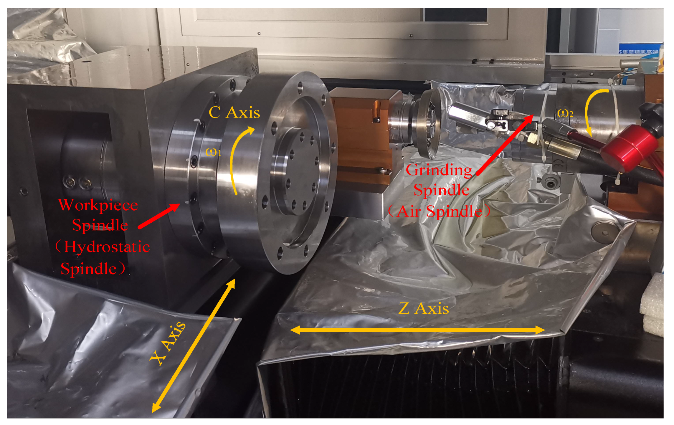
In high precision internal grinding machine, hydrostatic spindle is mainly used on axis C for clamping a workpiece which showed in Figure 1. The spindle is fixed on the X-axis for lateral translation, and the workpiece is fixed on the spindle for rotation at ω1 speed. The grinding wheel is fixed on the Y axis and fed longitudinally to achieve the purpose of grinding.
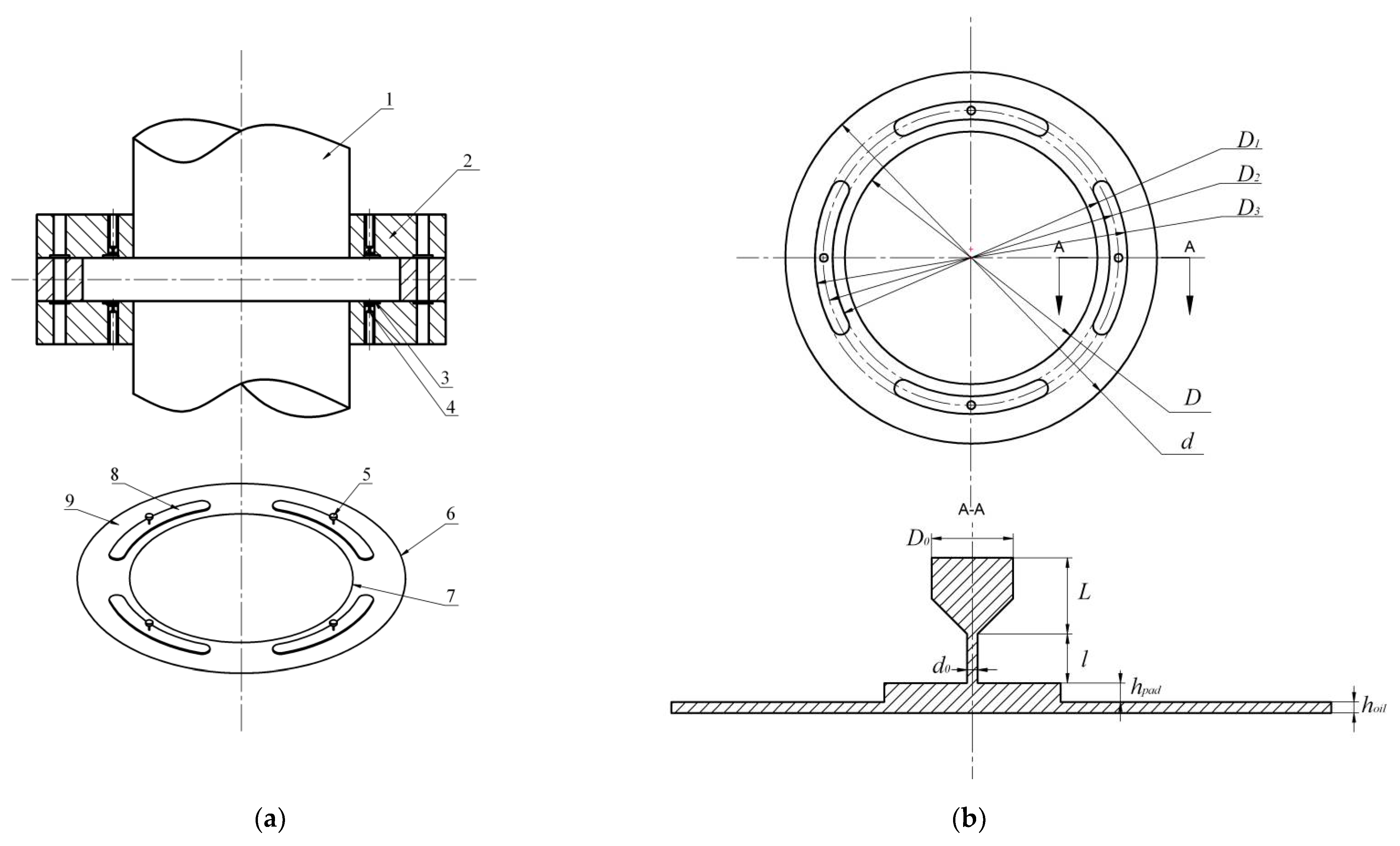
The thrust bearing plays a major role in the axial stiffness and position accuracy of high precision grinding machine. The schematic of the hydrostatic thrust bearing is shown in Figure 2a, the spindle rotates clockwise and moves relative to the thrust bearing, of which 1 is the hydrostatic shaft, 2 is the pad of hydrostatic thrust bearing, 3 is the oil film and 4 is the orifice restrictor, 5 is the oil pressure inlet and 6, 7 are the outlet of inner ring and outer ring respectively, 8 is the oil pad, 9 is the oil film.
The schematic illustration of structural dimensions and local enlarged view are shown in Figure 2b. The inner diameter of the sealing land (d) is 93 mm, the outer diameter of the sealing land (D) is 136.8 mm, the inner diameter of the annular recess (D1) is 102 mm, the outer diameter of the annular recess (D3) is 115 mm. There are four static orifice restrictors distributed uniformly in circumferential direction, and the distribution circle diameter of the orifices (D2) is 108 mm. The oil inlet diameter (D0) is 3 mm, the oil inlet length (L) is 2.5 mm, orifice length (l) is 2 mm and the oil film thickness (hoil) is 0.02 mm.
3. Modelling and Analysis of the Hydrostatic Bearing Spindle
In recent years many scholars have conducted lots of research by this method which was verified by related experiments [25,26]. The commercial CFD software ANSYS Fluent was employed to numerically calculate oil pressure distribution, mass flow rate and oil temperature through the orifice and pad along the static oil film. In this study, the full Navier-stokes equations are used in this three-dimensional oil film model for numerical simulations, due to the Y direction is the normal direction of the thrust bearing, the influence of the direction on the bearing performance is not considered, the governing equation of this model can be expressed as:
where p is the supply oil pressure and u, w respectively indicate the flow velocity of the oil along X and Z directions. h is the oil film thickness, but in oil chamber filed, . The X is the tangential direction of the circumference and the Z is the radial direction of thrust bearing which is the main capacity direction [27]. In Figure 2b A-A face, dynamic eddy current will be formed in this area with the change of pressure gradient under the condition of high pressure and high speed. In this area of dynamic pressure equation can be expressed as:
In the previous research, only the variation of bearing capacity with different conditions in X and Z directions are considered, but the gradient change in Y direction under high pressure and high speed is ignored [28,29], where ∑P0 is Y direction total pressures, P1 is the oil film thickness pressure and P2 is the oil pad thickness pressure [30]. The boundary conditions chosen in the calculation of the oil film in the hydrostatic bearing are composed of the inlet boundary of the pressure, the outlet boundary of the pressure, the periodic boundary, and the rotating wall boundary. In orifice area, realizable k-ε turbulence model is employed in the CFD model [30,31].
In order to more accurately calculate the performance of thrust bearings, in this paper the Reynolds assumes that both density and viscosity vary with pressure and temperature [32]. The density and viscosity can be expressed as:
where is the density with pressure and temperature change, is the initial density of oil. is the oil viscosity at any time with the change of working conditions, is the viscosity of oil at rest, is the coefficient of viscosity (), is temperature of under actual conditions, is the initial temperature, in this simulation we take 296 K.
4. Simulation Development, Results and Discussion
In this paper, to estimate the performance of hydrostatic thrust bearing more efficiently and accurately. The relationship between density and viscosity with pressure and temperature change is considered by UDFs. The oil supply pressure (Ps) is 0~3 MPa, the thrust surface rotation speed (ω) of hydrostatic bearing at 0~4000 r/min. In this condition, the throttle orifice position will produce micro eddy current phenomenon. At the same time, there will be small bubbles in the vortex region. In order to improve the performance of hydrostatic thrust bearings, it is necessary to calculate and discuss the influence of varied the working condition and the size of the orifice shape on the hydrostatic thrust bearing performance under the change of viscosity with temperature.
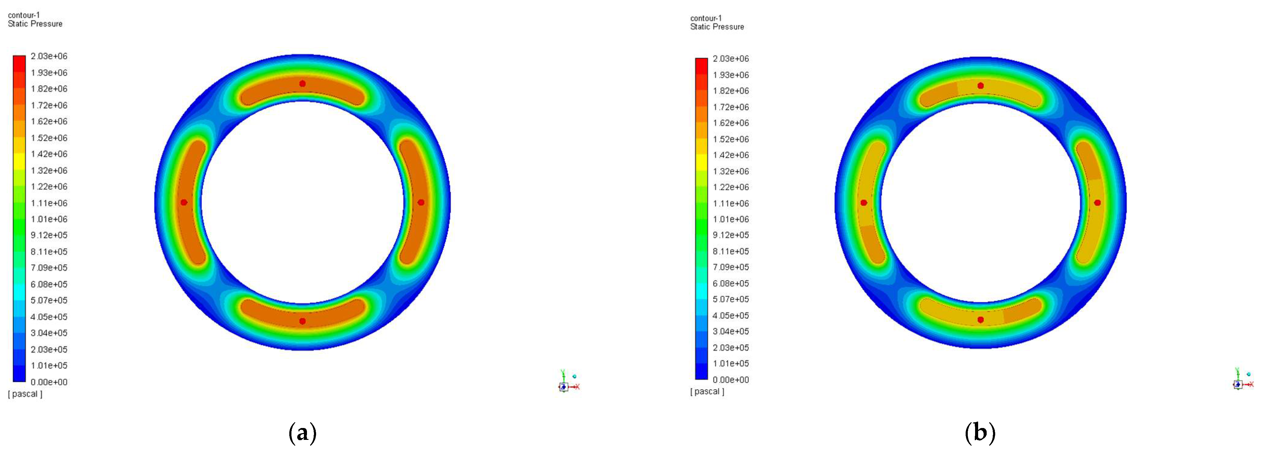
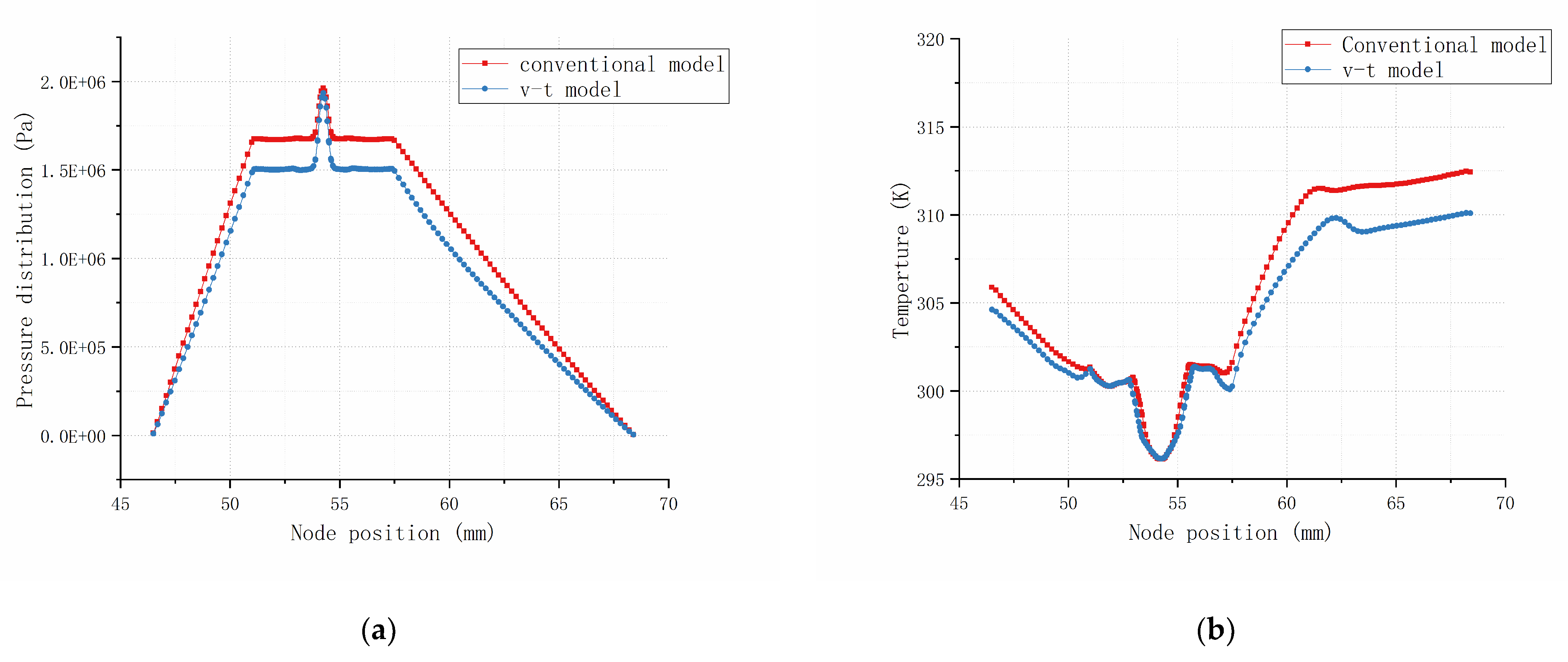
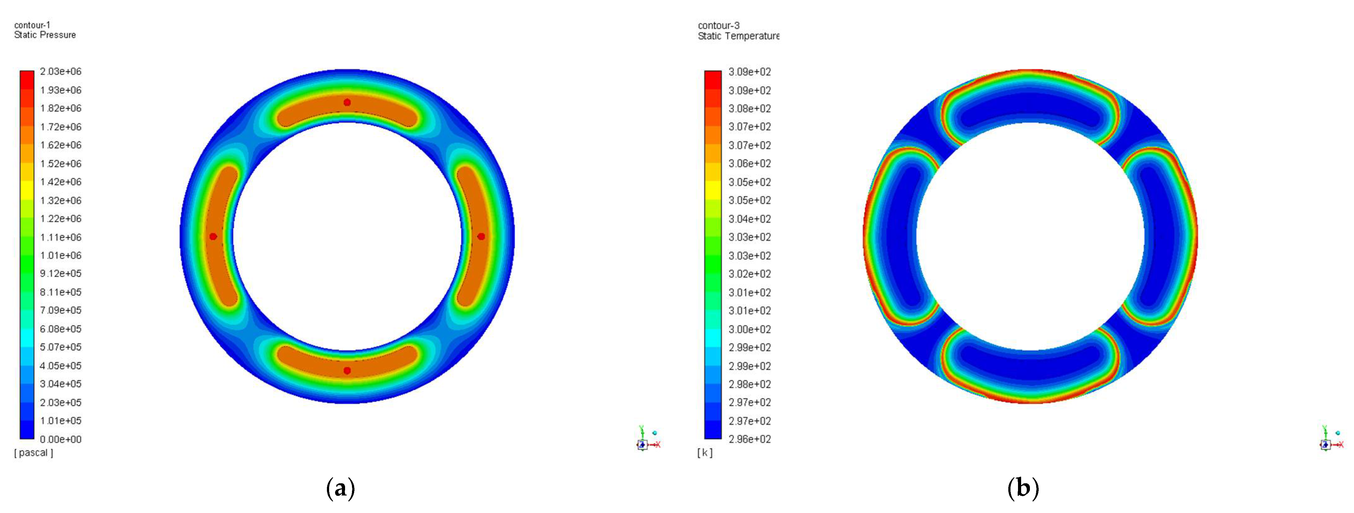
To compare with conventional model method and viscosity-temperature (v-t) model method the static pressure contours are shown in Figure 3. The working condition is given, which supply oil pressure is 2 MPa (20 atm), rotation speed is 2000 r/min, the lubricating oil initial density is 869 Kg/m3 and initial viscosity is 0.00405 Kg·m/s. It can be found from Figure 3 that the pressure gradually decreases from the oil supply position, the position of the inner circle and outer circle outlet is the same as the indoor atmospheric pressure. However, different from the conventional method, the pressure distribution in the v-t method which is shown in Figure 3b, is shifted towards the rotation direction due to the influence of heat generated by the friction between the rotating speed and the oil film.
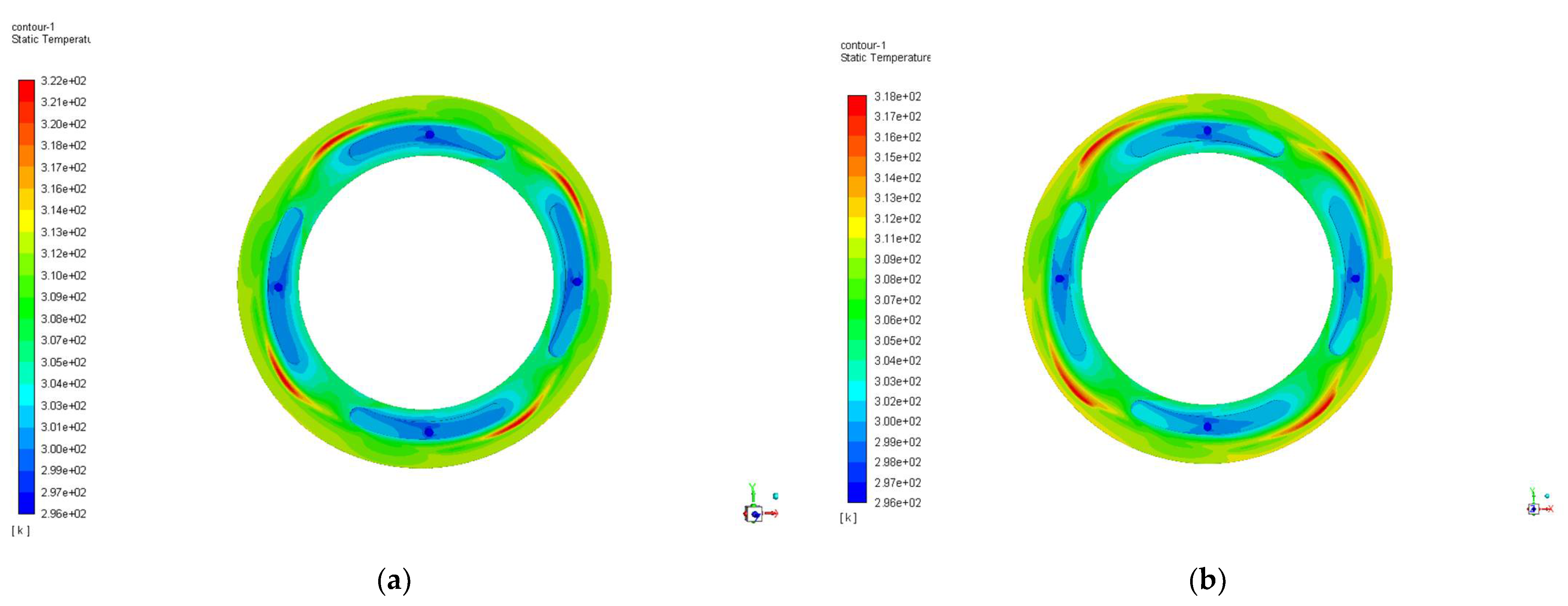
The speed of the hydrostatic thrust bearing designed is relatively high, the outer shaft temperature can be cooled by physical cooling method, but the inner shaft temperature is not easy to be dispersed at high speed. In order to prevent the shaft temperature being too high between the spindle and the bearing bush, the oil pad position is offset 15% to the inner part of the shaft. It can found from Figure 4 that the maximum temperature is occurred near the outlet, the conventional model is 322 K, higher than v-t model 318 K. It can be concluded that with the temperature rises, the viscosity of the lubricating oil decreases, the shear thinning effect took away more heat.
The pressure and temperature distribution along the slice line A-A for a different method is seen in Figure 5. It can be found that when the initial situation was the same, the total pressure distribution lower than a conventional model. The v-t model was decreasing exponentially, distinct from the conventional model which was linear decreasing. The temperature gradually increased from the oil supply port to the oil outlet, and experienced two fluctuations, the first time in the oil pad position area, the temperature is lower because the oil pad position needs to be filled with lubricating oil; the second time was occurred near outlet, because the oil film is very thin, the bearing relative motion friction produces the heat, due to the lubricating oil temperature to rise, the density and the viscosity will decrease. We can consider that the temperature rise has a certain effect on the bearing capacity of hydrostatic thrust bearing, and mainly in the orifice, oil pad, outer circle outlet position.
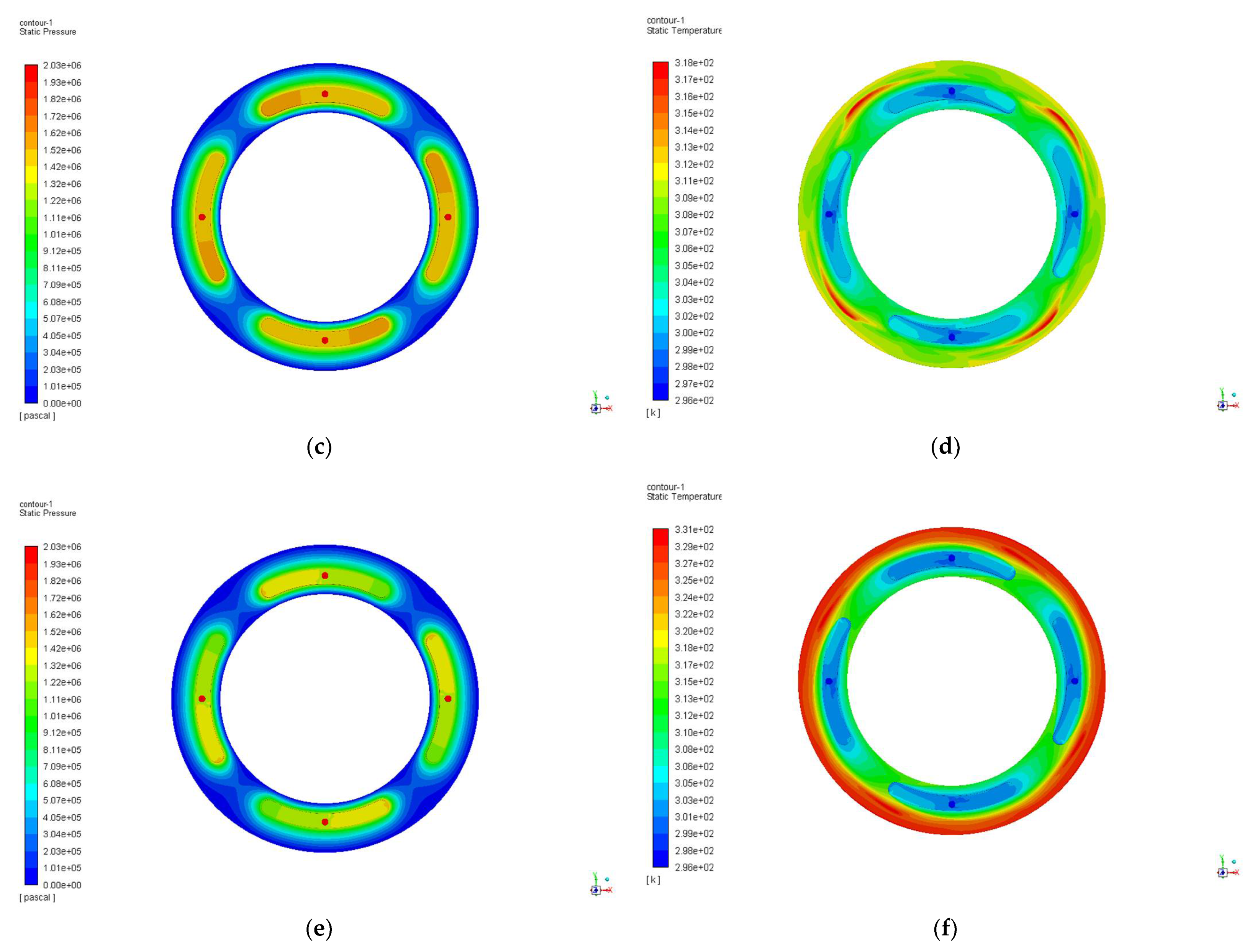
When the oil supply pressure is 2 MPa and the rotation speed is 0 r/min, the hydrostatic thrust bearing is in a static state. The lubricating oil from the orifice into the oil pad and then to the oil film is evenly distributed. The oil film thickness is only 0.02 mm, under the action of pressure the temperature went up from 296 K to 309 K, which is shown in Figure 6a,b. When the rotation speed is 2000 r/min, the pressure in the oil pad starts to tilt to one side as the rotation speed changes, and the pressure in the oil pad is 1.72 MPa and decreased by 6.01%. The temperature also increased with the rotation speed, especially the oil film surface temperature increase is more obvious, but the highest temperature occurs in the outer circle of the effective bearing zone of the oil film and then there was a gradual decline, it can be found in Figure 6c,d. When the rotate speed is 4000 r/min, the pressure in oil pad is 1.41 MPa, decreased by 22.95%, the temperature increased gradually from the orifice position and the highest temperature reached 331 K, it can be found in Figure 6e,f.
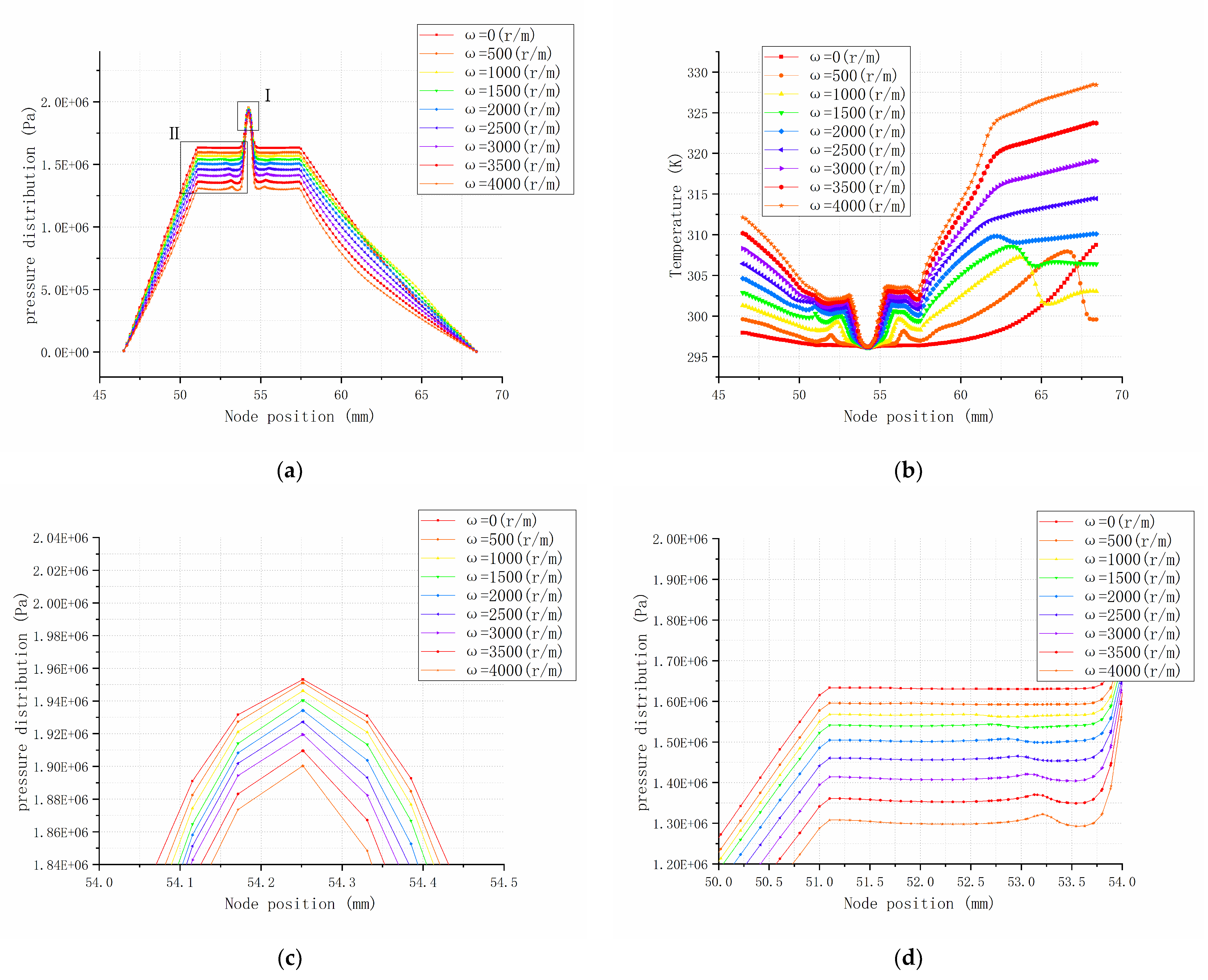
To investigate the influence of various rotation speeds on pressure distribution of the thrust face, the static pressure at different rotation speed is calculated in Figure 7. At the same supply oil pressure which takes 2 MPa in this calculation, it can be found that the pressure decreases with increasing rotational speed, because the temperature will increase with the change of rotational speed under the action of friction, when ω = 0 the thrust bearing is in steady state and the temperature rises gently, when ω = 500~2000 r/min the temperature of thrust bearing has an obvious temperature attenuation at the outlet of the outer circle, because in this situation, the effective bearing area of oil film, the normal force greater than tangential force; when ω = 2500~4000 r/min the temperature rises gradually. In Figure 7c the maximum pressure zone is the pressure inlet, when rotation speed is 4000 r/min the top point is 1.94 MPa less than 2 MPa, it can be considered that the shear force produced by high rotational speed reduces oil supply pressure. The oil pad area pressure distribution is shown in Figure 7d, in this area the pressure is almost at the equal level, because the oil pad can be steady and uniform the oil pressure. But the pressure of the slice line A-A profile decreases gradually with the increase of rotational speed. Along with this phenomenon, there will be obvious pressure fluctuation near the orifice. This is the main reason that affects the rotary precision of the thrust surface of the hydrostatic bearing.
Different from changing the oil supply pressure with constant oil supply pressure, changing the oil supply pressure when the speed is 2000 r/min, the pressure distribution gradually becomes uniform by bias on one side, the maximum static pressure is located in the center of the throttle orifice, it can be found in Figure 8a,c,e. The temperature from the inlet hole to the outlet gradually increases, however, the temperature region is evenly distributed at the outer circle exit of the axial tile at 1 MPa oil supply pressure which is shown in Figure 8b. When the oil supply pressure increases, the highest temperature is mainly concentrated in the position without the oil pad and spreads outward which showed in Figure 8d,f. We can infer that this is because the oil pad can act as an equilibrium temperature. As the oil supply pressure increases, the temperature increases without the position of the oil pad, and when the oil supply pressure is raised, the overall temperature will be more concentrated.
In order to calculate the performance of hydrostatic thrust bearing more accurately, it is necessary to study the influence of changing oil supply pressure on bearing performance under specified rotational speed. When the speed is fixed at 2000 r/min, it can be found that the steady pressure increases with the increase in oil supply pressure, the more the oil supply pressure and the greater the steady bearing pressure in Figure 9a. The overall temperature trend is basically consistent shown in Figure 9b, but in oil pad area and outer circle outlet of hydrostatic thrust bearing, the temperature curve fluctuates obviously. When the oil supply pressure is 1.0 MPa, the temperature change is relatively gentle, the maximum temperature is 310.16 K at the outlet. When the supply pressure is greater than 2 MPa, there is a marked change of temperature at the outlet. When the oil supply pressure is 3 MPa, the maximum temperature is 313.05 K, appears at 64 mm from the center of the thrust bearing, and the temperature at the outlet position is 310.31 K, growth of 0.88%. It can be considered that the effect of shear thinning on temperature rise under the viscous-temperature model is obvious, and the effective carrying area is nearly 64 mm from the center of the thrust bearing. This provides a basis for the accurate calculation of the performance of the hydrostatic thrust bearing. Therefore, it is meaningful to analyze the influence of bearing configuration on fluctuation.
In previous studies we found that few scholars studied the effect of liquid static bearing orifice configurations on thrust face [33,34]. In general, hydrostatic bearings are considered to be equal density, viscosity, and over damping system. Small bubbles will be formed around the restriction orifice and oil film, this is the main reason for the oil temperature rise and viscosity decrease under stable condition.
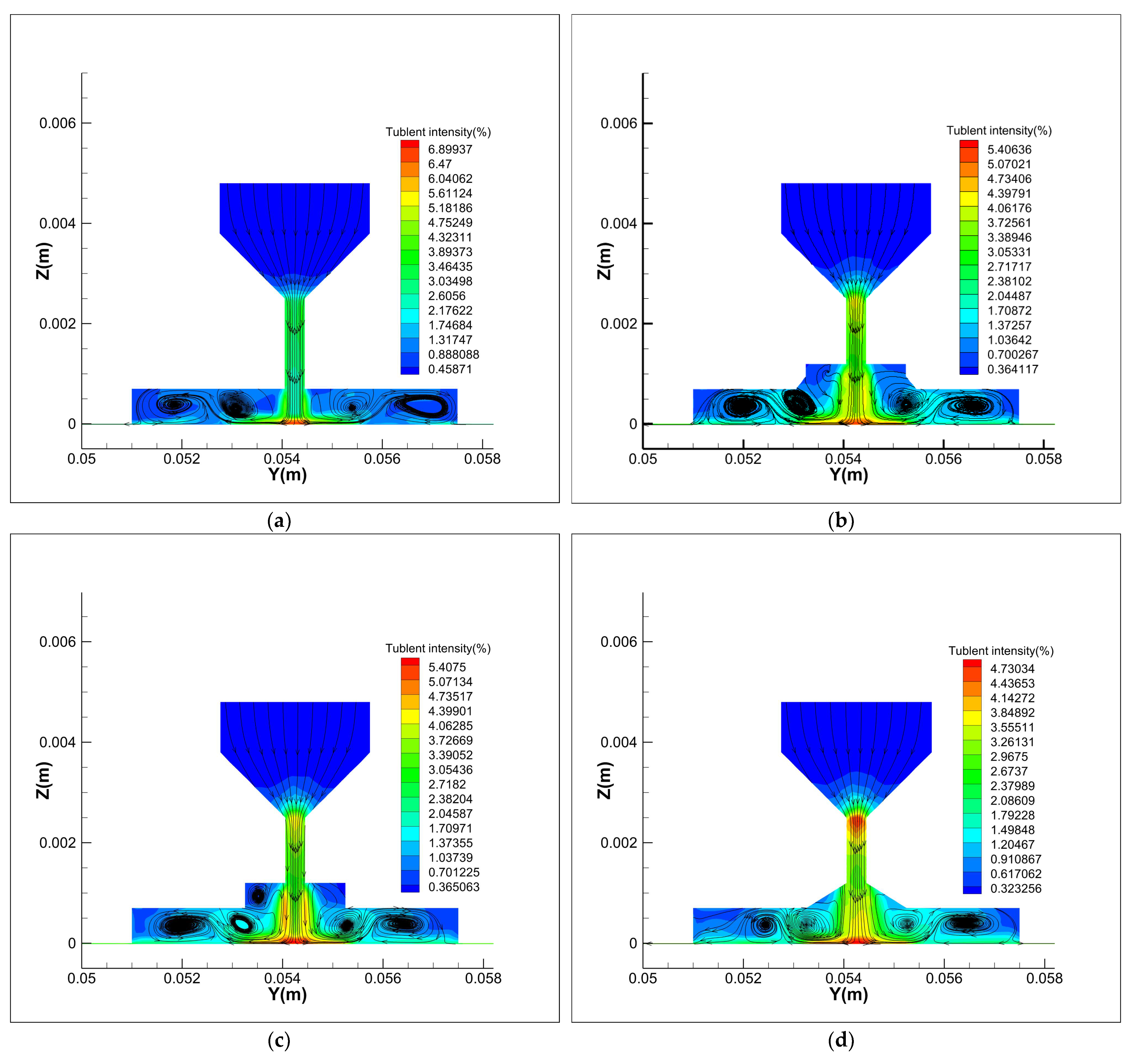
With the improvement of design requirements of thrust bearing, the calculation accuracy is also improved. Therefore, the turbulent fluctuation of the orifice position cannot be ignored. When the pressure of the oil inlet is 2 MPa and the rotation speed is 2000 r/min, the turbulence intensity model of the four configurations are compared to reduce the pressure fluctuation of oil film caused by the turbulence of the oil inlet. Figure 10 is shown the contours of turbulence intensity and the track of velocity of four different orifice types. These four types are mainly given according to the common machining configurations mode of orifice.
The first one is normal type which the lubricating oil enters the oil chamber directly, by calculating, we concluded that the turbulence intensity of this type is the largest, and the maximum intensity appears in the inlet hole perpendicular to the bottom of the oil pad. As we found in previous calculations of load capacity and temperature, the hydraulic fluid creates vortexes in the oil pad position, so there are pressure and temperature fluctuations in this area. The immersed hole type and both immersed and taper hole type turbulence intensity are similar which is shown in Figure 10b,c, but the immersed hole type formed more vortices at the corner, this is detrimental to the rotation of thrust bearing. The taper hole type is the smallest turbulence intensity of four types, and the intensity of the turbulence at the orifice is the most uniform. Based on the above analysis, we finally choose taper hole type as the configuration of the orifice.
5. Application Case Study
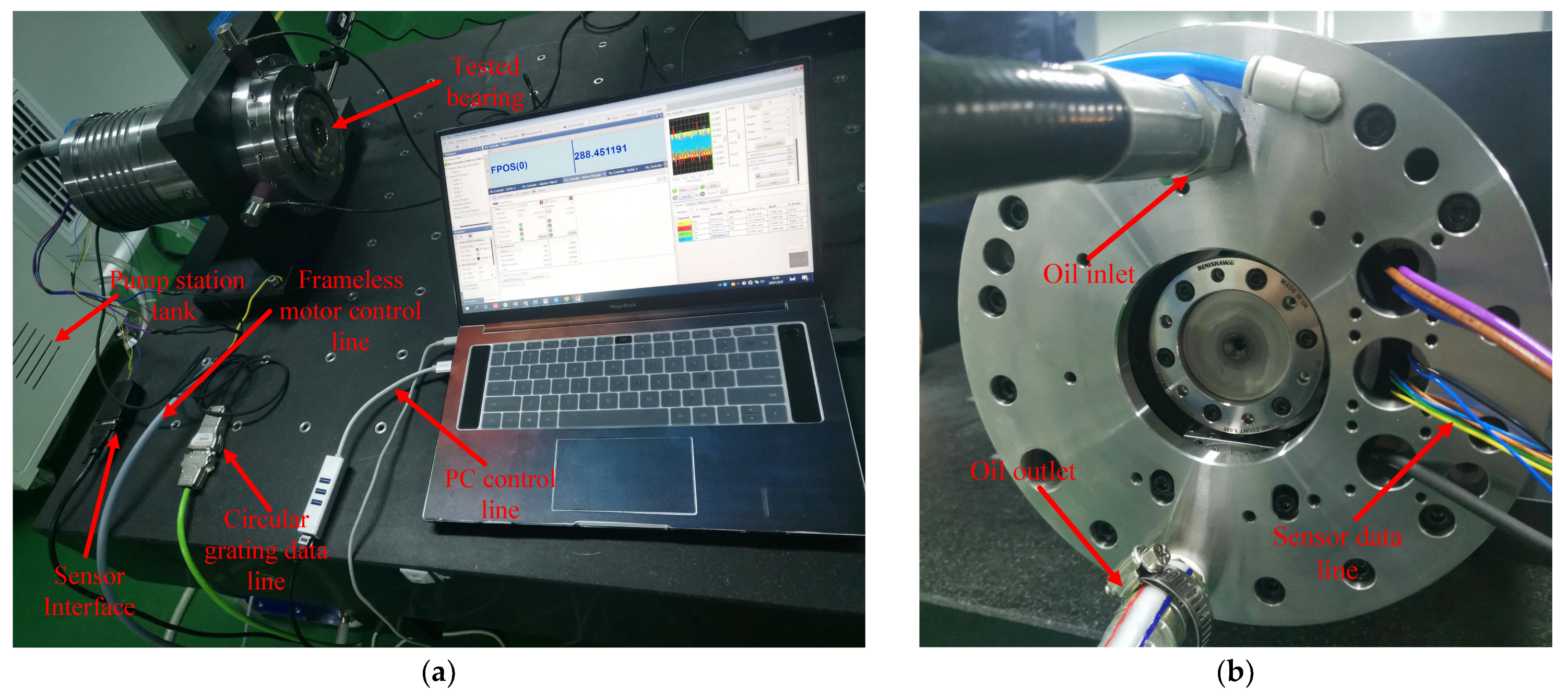
In order to verify the validity and accuracy of the simulation, we carried out experiments on the above calculated conditions [35]. To ensure that the thrust surface of the hydrostatic bearing is not affected by external force, the transverse position of the bearing is used to measure the thrust surface shown in Figure 11a. The lubricating oil pump is fed into the bearing through the oil pump, the cooling water tank is used to ensure the initial oil supply temperature is 296 K. Driven by a Kermorgan frameless motor at the end of the bearing, the maximum rotational speed is 5000 r/min.
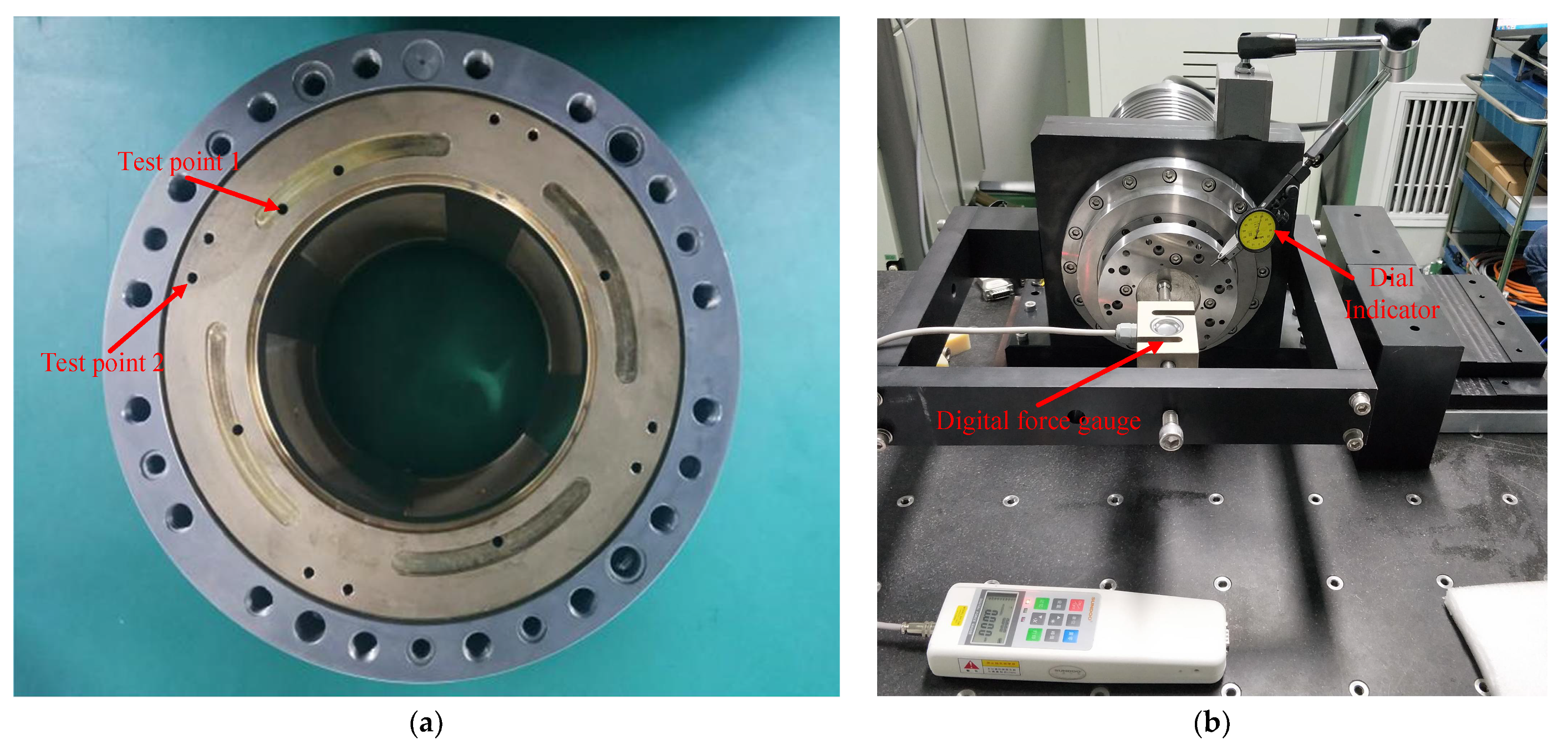
It is difficult to measure the overall pressure and temperature distribution inside the hydrostatic bearing [36]. In this experiment, a through hole with a diameter of 0.1 mm was drilled at the two key positions of the oil pad position and the outlet position on the thrust surface which shown in Figure 11b, the bearing was made of copper and the bearing sleeve is made of stainless steel. From the simulation results, it is not difficult to see that the maximum pressure position of the thrust surface is in the oil inlet hole and diffuses in the oil pad. The average pressure is mainly distributed in the oil pad. Different from the pressure distribution, the highest temperature appears at the oil outlet of the oil film.
Based on the distribution trends of simulation results. In Figure 12a test point 1 is located in the oil pad position of the bearing, we chose SMC PSE576 pressure sensor, rated pressure range of 0~5 MPa, mainly used to measure the internal pressure of the oil chamber. Test point 2 is located on the outside of the thrust surface of the bearing which is mainly used to measure the oil temperature and flux of the lubricating oil. Each group was controlled for 3 times to take the average value. In Figure 12b is the measurement of axial stiffness of liquid sliding spindle—the dial gauge was mounted on the tooling surface to measure the axial displacement, the digital force gauge which the maximum capacity is 10 KN, the load resolution is 0.005 KN, was used to measure the change of surface loading force, and then adjust the oil film clearance to calculate the support stiffness of the spindle.
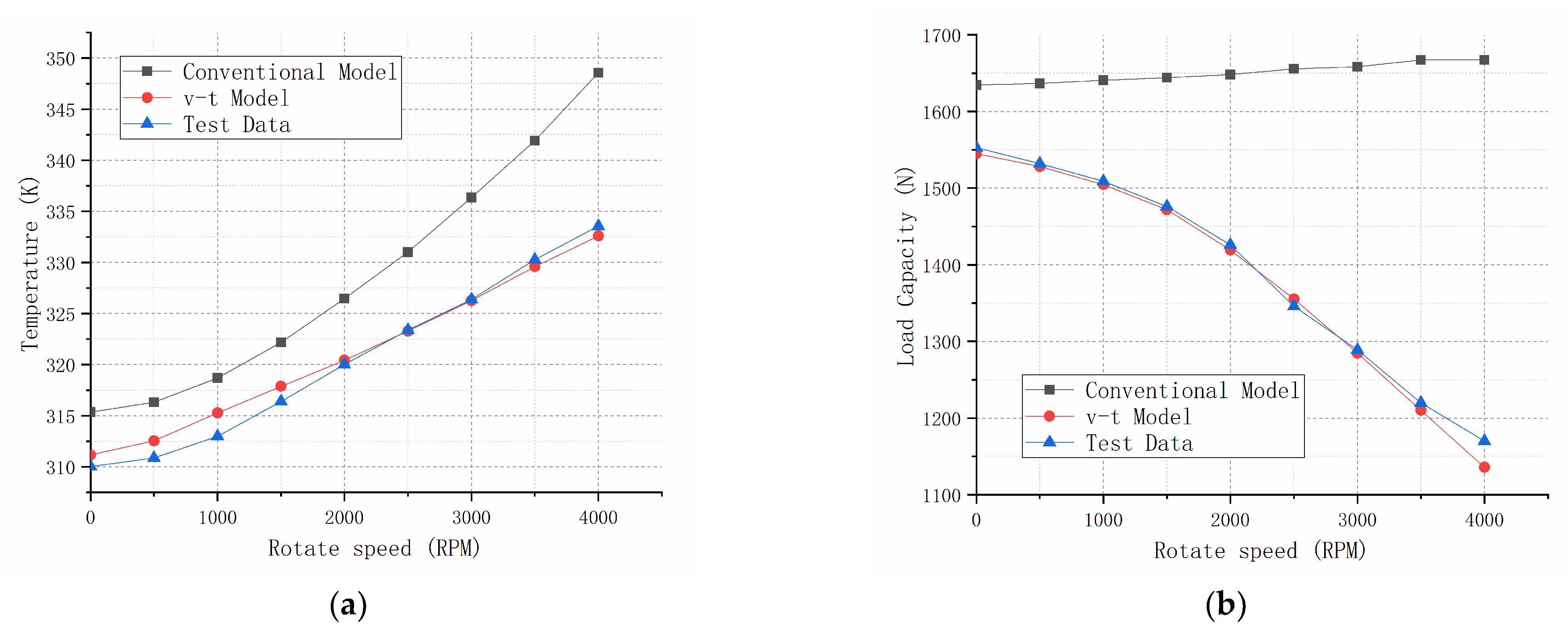
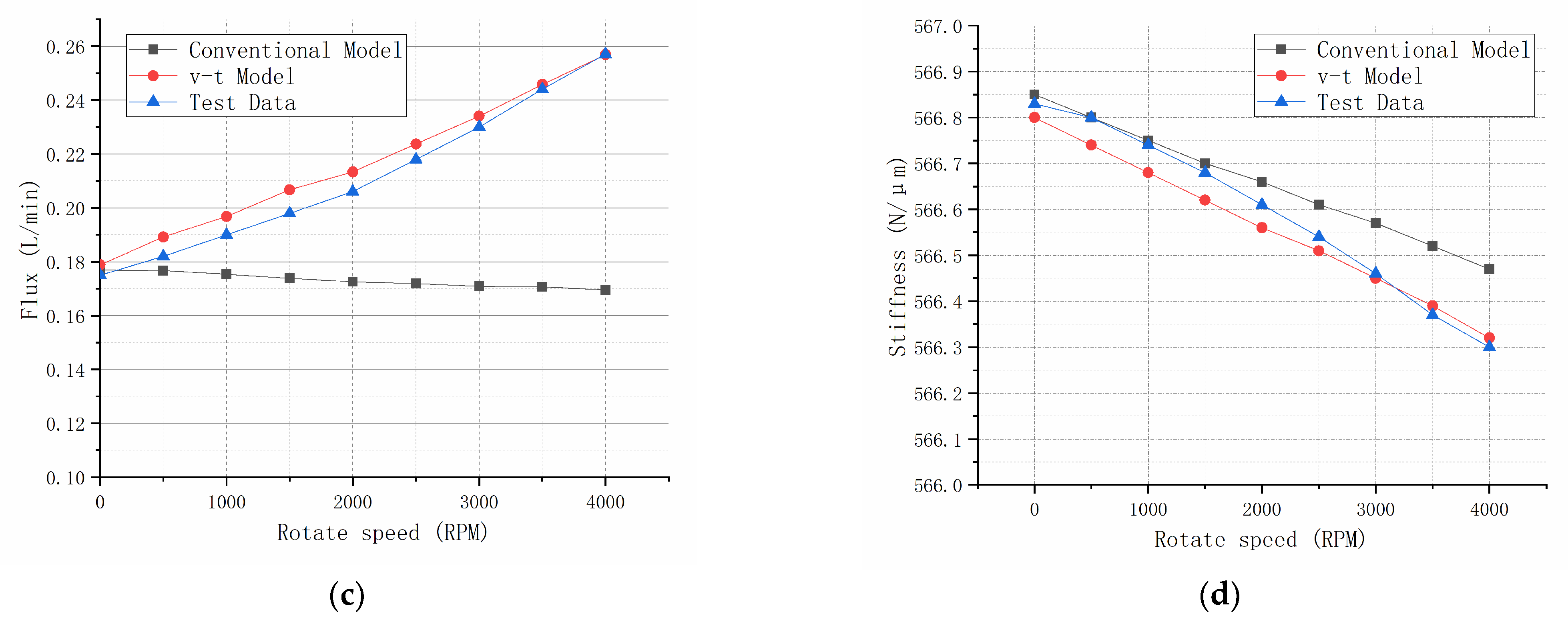
In this paper, it can be found that the variation trends at different rotation speeds from 0 to 4000 r/min as illustrated in Figure 13. The average temperature has an obvious increasing trend with the increase of rotating speed, with the shear thinning effect, the trend of temperature rise is lower than that of conventional models. This is confirmed by experimental values, because of the measured oil outlet temperature, the temperature is slightly lower than the simulation value but the tendency is almost uniform, which is shown in Figure 13a. In the no-load condition, the average bearing capacity of thrust surface decreases with the increase of rotational speed. The result of the v-s model is closer to the experiment, because with the increase of rotating speed, the viscosity decreases with the increase of temperature. When the hydrostatic bearing rotates at high speed, the circumferential shear force will reduce the axial force, as can be seen in Figure 13b. Different from the conventional calculation model, the flow rate of lubricating oil gradually increases with the speed. This is also confirmed by the experimental data which is shown in Figure 13c. The axial stiffness of the spindle decreases with the increase of rotational speed in Figure 13d, when the rotation speed is at 4000 r/min, it is most obvious that the v-t model is closer to the actual measured value.
6. Conclusions
This paper attempts to present a precision engineering-oriented approach to design and analysis of the hydrostatic bearing and the spindle with the application to a high precision internal grinding machine. It has presented the influence of hydrostatic thrust bearing on bearing capacity and temperature working with high speed and high pressure on a high precision spindle. In order to be able to design and analyze the bearing performance more accurately, an innovative viscosity-temperature model is proposed based on the CFD method. Furthermore, considering the influence of eddy current phenomenon on the precision of high-speed hydrostatic bearing, the configuration of oil inlet throttle is analyzed and studied in the context of precision machine design requirement. The following conclusions are drawn up particularly by comparing the experimental and simulation results:
- (1)
- The viscosity-temperature model plays a significant role in the accurate design and analysis of high pressure and high-speed hydrostatic bearings and the consequent spindle, particularly considering the oil supply pressure and speed are changed. The simulation results on the variation trend of temperature, bearing loading capacity and flow rate are consistent with those of the experiment.
- (2)
- From the overall pressure and temperature contours analysis, when the oil supply pressure is 2 MPa to change the rotating speed, the bearing capacity of the static thrust bearing deviates to one side of the oil cavity with the increase of the speed, and gradually decreases. The temperature increases with the increase of the rotating speed, and the highest temperature is generated in the outer ring of the oil outlet. When the rotating speed is 2000 r/min to change the oil supply pressure, the higher the oil supply pressure is, the more concentrated oil pressure in the oil pad increases.
- (3)
- Analysis from the A-A profile, when the oil supply pressure is 2 MPa to change the rotating speed, the pressure distribution decreases gradually from the oil orifice position through the oil pad. The higher the rotating speed, the more obvious the pressure fluctuation is near the oil pad. When the bearing spindle rotating speed is varied from 0 to 2000 r/min, the oil temperature at the outlet position has obvious fluctuation; when the rotating speed is varied from 2000 to 4000 r/min, the temperature curve tends to change gently, although the bearing working temperature increases significantly.
- (4)
- When the bearing spindle rotating speed is at 2000 r/min while changing oil supply pressure, the pressure near the orifice increases obviously, but the average pressure in the oil pad does not increase significantly. When the oil supply pressure is at 0.5 to 1.5 MPa, the bearing temperature rises gently; when the oil supply pressure is greater than 2 MPa, the temperature will fluctuate significantly at the outlet, this is the main reason for causing the decrease of oil viscosity and bearing capacity.
- (5)
- According to the position fluctuation at the oil inlet hole, four different configurations of the orifice are analyzed. Taper hole type has the lowest turbulence intensity. It can effectively reduce the pressure fluctuation, the bearing spindle temperature and improve the carrying capacity.
Author Contributions
Conceptualization, Y.S.; Methodology, K.C.; Software, Y.S. and S.C.; Validation, Y.S. and H.D.; Data curation, Y.S.; Resources, Y.S. and S.C.; Writing—original draft, Y.S.; Writing—review & editing, Y.S. and K.C. All authors have read and agreed to the published version of the manuscript.
Funding
This research received no external funding.
Institutional Review Board Statement
Not applicable.
Informed Consent Statement
Not applicable.
Acknowledgments
The authors thank for the technical and experimental support on this research from engineers at JITRI UpTech Ltd.
Conflicts of Interest
The authors declare no conflict of interest.
References
- Brinksmeier, E.; Mutlugünes, Y.; Klocke, F.; Aurich, J.C.; Shore, P.; Ohmori, H. Ultra-precision grinding. CIRP Ann. 2010, 59, 652–671. [Google Scholar] [CrossRef]
- Rowe, W.B. Hydrostatic, Aerostatic and Hybrid Bearing Design; Elsevier: Amsterdam, The Netherlands, 2012. [Google Scholar]
- Chen, S.; Yang, S.; Liao, Z.; Cheung, C.F.; Jiang, Z.; Zhang, F. Curvature effect on surface topography and uniform scallop height control in normal grinding of optical curved surface considering wheel vibration. Opt Express 2021, 29, 8041. [Google Scholar] [CrossRef] [PubMed]
- Gupta, M.K.; Khan, A.M.; Song, Q.; Liu, Z.; Khalid, Q.S.; Jamil, M.; Kuntoğlu, M.; Usca, Ü.A.; Sarıkaya, M.; Pimenov, D.Y. A review on conventional and advanced minimum quantity lubrication approaches on performance measures of grinding process. Int. J. Adv. Manuf. Technol. 2021, 117, 729–750. [Google Scholar] [CrossRef]
- Zieliński, B.; Kapłonek, W.; Sutowska, M.; Nadolny, K. Analysis of a Feasibility Study of a Precision Grinding Process for Industrial Blades Used in the Cutting of Soft Tissues by a Prototype 5-Axis CNC Grinding Machine. Appl. Sci. 2019, 9, 3883. [Google Scholar] [CrossRef] [Green Version]
- Wu, M.; Guo, B.; Zhao, Q.; He, P. Precision grinding of a microstructured surface on hard and brittle materials by a microstructured coarse-grained diamond grinding wheel. Ceram. Int. 2018, 44, 8026–8034. [Google Scholar] [CrossRef]
- He, C.L.; Zong, W.J.; Zhang, J.J. Influencing factors and theoretical modeling methods of surface roughness in turning process: State-of-the-art. Int. J. Mach. Tools Manuf. 2018, 129, 15–26. [Google Scholar] [CrossRef]
- Urreta, H.; Aguirre, G.; Kuzhir, P.; Lopez De Lacalle, L.N. Actively lubricated hybrid journal bearings based on magnetic fluids for high-precision spindles of machine tools. J. Intell. Mater. Syst. Struct. 2019, 30, 2257–2271. [Google Scholar] [CrossRef] [Green Version]
- Hanoca, P.; Ramakrishna, H.V. To Investigate the Effect of Oil Film Thickness at the Entrance of the Infinitely Long Slider Bearing Using CFD Analysis. Procedia Eng. 2015, 127, 447–454. [Google Scholar] [CrossRef] [Green Version]
- Zha, J.; Chen, Y.; Zhang, P. Precision design of hydrostatic thrust bearing in rotary table and spindle. Proc. Inst. Mech. Eng. Part B J. Eng. Manuf. 2018, 232, 2044–2053. [Google Scholar] [CrossRef]
- Kashchenevsky, L.; Johnson, D. Theoretical Analysis of Rotational Accuracy for Thrust Hydrostatic Bearings. In Proceedings of ASPE Summer Topical Meeting on Precision Bearings and Spindles, State College, PA, USA, 11–12 June 2007; pp. 7–9. [Google Scholar]
- Chen, D.; Gao, X.; Zha, C.; Pan, R.; Fan, J. Tilt Angle of Hydrostatic Spindle Influenced by Microscale Effects. Tribol. Trans. 2020, 63, 28–37. [Google Scholar] [CrossRef]
- Yadav, S.K.; Sharma, S.C. Performance of hydrostatic tilted thrust pad bearings of various recess shapes operating with non-Newtonian lubricant. Finite Elem. Anal. Des. 2014, 87, 43–55. [Google Scholar] [CrossRef]
- Hanawa, N.; Kuniyoshi, M.; Miyatake, M.; Yoshimoto, S. Static characteristics of a water-lubricated hydrostatic thrust bearing with a porous land region and a capillary restrictor. Precis. Eng. 2017, 50, 293–307. [Google Scholar] [CrossRef]
- Zha, J.; Chen, Y.; Zhang, P.; Chen, R. Effect of design parameters and operational conditions on the motion accuracy of hydrostatic thrust bearing. Proc. Inst. Mech. Eng. Part C J. Mech. Eng. Sci. 2020, 234, 1481–1491. [Google Scholar] [CrossRef]
- Ferron, J.; Frene, J.; Boncompain, R. A Study of the Thermohydrodynamic Performance of a Plain Journal Bearing Comparison between Theory and Experiments. J. Lubr. Technol. 1983, 105, 422–428. [Google Scholar] [CrossRef]
- Zouzoulas, V.; Papadopoulos, C.I. 3-D thermohydrodynamic analysis of textured, grooved, pocketed and hydrophobic pivoted-pad thrust bearings. Tribol. Int. 2017, 110, 426–440. [Google Scholar] [CrossRef]
- Horvat, F.E.; Braun, M.J. Comparative Experimental and Numerical Analysis of Flow and Pressure Fields Inside Deep and Shallow Pockets for a Hydrostatic Bearing. Tribol. Trans. 2011, 54, 548–567. [Google Scholar] [CrossRef]
- Fouflias, D.G.; Charitopoulos, A.G.; Papadopoulos, C.I.; Kaiktsis, L.; Fillon, M. Performance comparison between textured, pocket, and tapered-land sector-pad thrust bearings using computational fluid dynamics thermohydrodynamic analysis. Proc. Inst. Mech. Eng. Part J J. Eng. Tribol. 2015, 229, 376–397. [Google Scholar] [CrossRef]
- Chen, X.; He, X. The effect of the recess shape on performance analysis of the gas-lubricated bearing in optical lithography. Tribol. Int. 2006, 39, 1336–1341. [Google Scholar] [CrossRef]
- Gao, S.; Cheng, K.; Chen, S.; Ding, H.; Fu, H. CFD based investigation on influence of orifice chamber shapes for the design of aerostatic thrust bearings at ultra-high speed spindles. Tribol. Int. 2015, 92, 211–221. [Google Scholar] [CrossRef]
- Gao, S.; Shang, Y.; Gao, Q.; Lu, L.; Zhu, M.; Sun, Y.; Yu, W. CFD-Based Investigation on Effects of Orifice Length–Diameter Ratio for the Design of Hydrostatic Thrust Bearings. Appl. Sci. 2021, 11, 959. [Google Scholar] [CrossRef]
- Sharma, S.C.; Rajput, A.K. Effect of geometric imperfections of journal on the performance of micropolar lubricated 4-pocket hybrid journal bearing. Tribol. Int. 2013, 60, 156–168. [Google Scholar] [CrossRef]
- Sharma, S.C.; Yadav, S.K. A comparative study of full and partial textured hybrid orifice compensated circular thrust pad bearing system. Tribol. Int. 2016, 95, 170–180. [Google Scholar] [CrossRef]
- Eleshaky, M.E. CFD investigation of pressure depressions in aerostatic circular thrust bearings. Tribol. Int. 2009, 42, 1108–1117. [Google Scholar] [CrossRef]
- Belforte, G.; Raparelli, T.; Trivella, A.; Viktorov, V.; Visconte, C. CFD Analysis of a Simple Orifice-Type Feeding System for Aerostatic Bearings. Tribol. Lett. 2015, 58, 25. [Google Scholar] [CrossRef] [Green Version]
- Shao, J.; Liu, G.; Yu, X.; Zhang, Y.; Meng, X.; Jiang, H. Effect of recess depth on lubrication performance of annular recess hydrostatic thrust bearing by constant rate flow. Ind. Lubr. Tribol. 2018, 70, 68–75. [Google Scholar] [CrossRef]
- Gropper, D.; Harvey, T.J.; Wang, L. A numerical model for design and optimization of surface textures for tilting pad thrust bearings. Tribol. Int. 2018, 119, 190–207. [Google Scholar] [CrossRef]
- Zhang, H.; Liu, Y.; Hafezi, M.; Hua, M.; Dong, G. A distribution design for circular concave textures on sectorial thrust bearing pads. Tribol. Int. 2020, 149, 105733. [Google Scholar] [CrossRef]
- Cicone, T.; Marinescu, A.A.; Sorohan, S. A simple analytical model for an elastohydrostatic thrust bearing. IOP Conf. Ser. Mater. Sci. Eng. 2020, 724, 12041. [Google Scholar] [CrossRef] [Green Version]
- Aguirre, G.; Al-Bender, F.; Van Brussel, H. A multiphysics model for optimizing the design of active aerostatic thrust bearings. Precis. Eng. 2010, 34, 507–515. [Google Scholar] [CrossRef]
- Shang, Y.; Cheng, K.; Ding, H.; Chen, S. Multiscale Modelling and Analysis on the Heavy-duty Hydrostatic Journal Bearing for a Precision Press Machine. IOP Conf. Ser. Mater. Sci. Eng. 2020, 825, 12010. [Google Scholar] [CrossRef]
- Sharma, S.C.; Jain, S.C.; Bharuka, D.K. Influence of recess shape on the performance of a capillary compensated circular thrust pad hydrostatic bearing. Tribol. Int. 2002, 35, 347–356. [Google Scholar] [CrossRef]
- Li, Y.; Ding, H. Influences of the geometrical parameters of aerostatic thrust bearing with pocketed orifice -type restrictor on its performance. Tribol. Int. 2007, 40, 1120–1126. [Google Scholar] [CrossRef]
- Kozdera, M.; Drábková, S.; Bojko, M. Experimental equipment for measuring physical properties of the annular hydrostatic thrust bearing. EPJ Web Conf. 2014, 67, 2058. [Google Scholar] [CrossRef] [Green Version]
- Yu, X.; Fu, X.; Meng, X.; Liu, D.; Zhang, Y.; Wang, W. Experimental and Numerical Study on the Temperature Performance of High-Speed Circular Hydrostatic Thrust Bearing. J. Comput. Theor. Nanosci. 2015, 12, 1540–1545. [Google Scholar] [CrossRef]
Figure 1.
Experimental setup of the high precision grinding machine.

Figure 2.
Schematic configuration of the orifice compensated hydrostatic thrust bearing. (a) Hydrostatic thrust bearing and oil pad; (b) Schematic illustration of structural dimensions and local enlarged view of A-A.
Figure 2.
Schematic configuration of the orifice compensated hydrostatic thrust bearing. (a) Hydrostatic thrust bearing and oil pad; (b) Schematic illustration of structural dimensions and local enlarged view of A-A.

Figure 3.
Static pressure contours comparison of conventional model and v-t model. (a) Pressure contour of conventional method; (b) Pressure contour of viscosity-temperature method.
Figure 3.
Static pressure contours comparison of conventional model and v-t model. (a) Pressure contour of conventional method; (b) Pressure contour of viscosity-temperature method.

Figure 4.
Static temperature contours comparison of conventional model and v-t model. (a) Temperature contour of conventional method; (b) Temperature contour of viscosity-temperature method.
Figure 4.
Static temperature contours comparison of conventional model and v-t model. (a) Temperature contour of conventional method; (b) Temperature contour of viscosity-temperature method.

Figure 5.
Static pressure and temperature patterns comparison along the slice line A-A. (a) Pressure distribution along the slice line; (b) Temperature distribution along the slice line.
Figure 5.
Static pressure and temperature patterns comparison along the slice line A-A. (a) Pressure distribution along the slice line; (b) Temperature distribution along the slice line.

Figure 6.
Static pressure and temperature contours of various rotate speeds. (a) Pressure contours at 0 r/min; (b) Temperature contours at 0 r/min; (c) Pressure contours at 2000 r/min; (d) Temperature contours at 2000 r/min; (e) Pressure contours at 4000 r/min; (f) Temperature contours at 4000 r/min.


Figure 7.
Static pressure and temperature distribution of various rotate speeds along the slice line A-A. (a) Pressure distribution at different rotational speeds (ω = 0~4000 r/min); (b) Temperature distribution at different rotational speeds (ω = 0~4000 r/min); (c) Local enlarged view of I; (d) Local enlarged view of II.

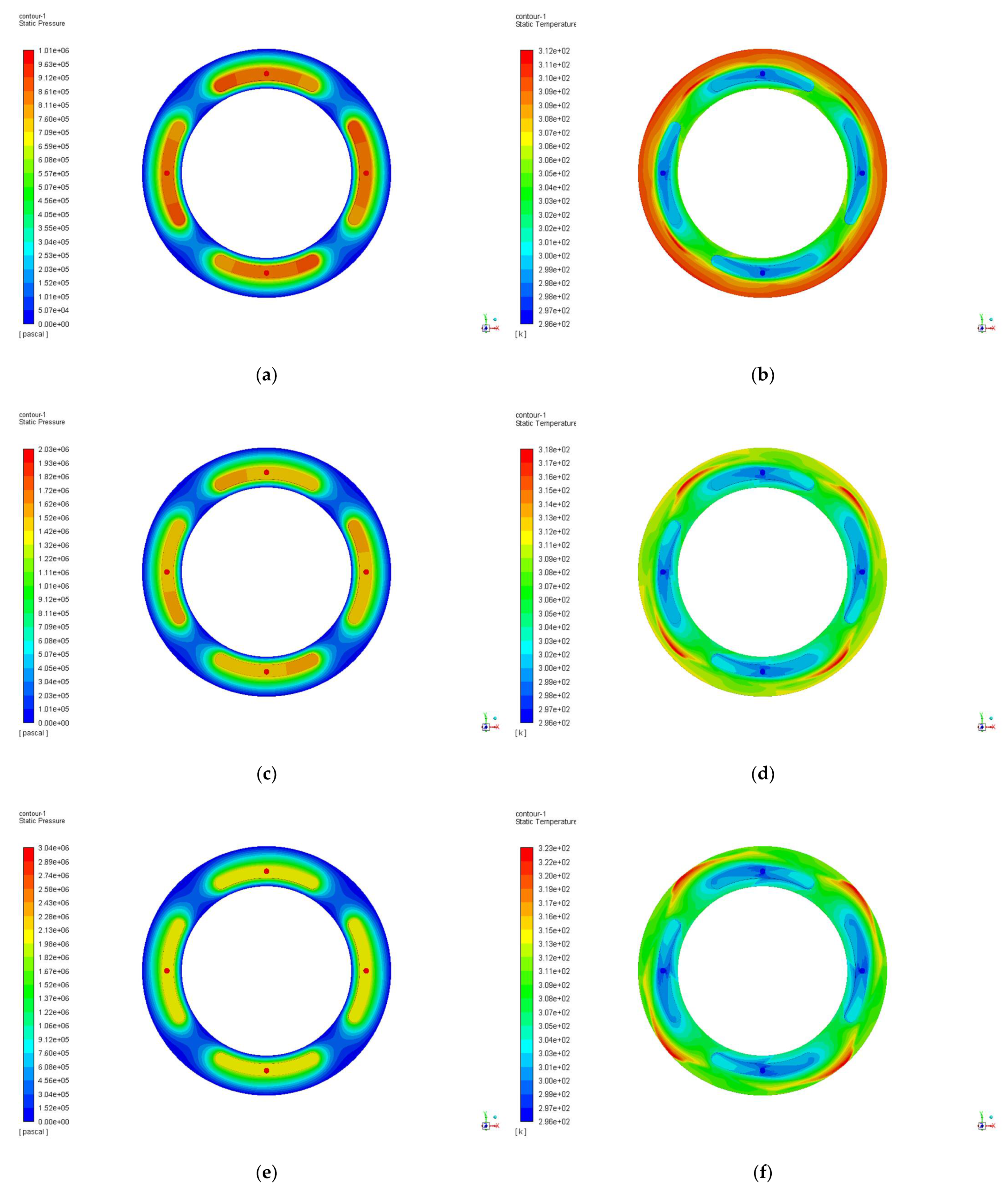
Figure 8.
Static pressure and temperature contours of various supply pressure. (a) Pressure contours at 1 MPa; (b) Temperature contours at 1 MPa; (c) Pressure contours at 2MPa; (d) Temperature contours at 2 MPa; (e) Pressure contours at 3 MPa; (f) Temperature contours at 3 MPa.
Figure 8.
Static pressure and temperature contours of various supply pressure. (a) Pressure contours at 1 MPa; (b) Temperature contours at 1 MPa; (c) Pressure contours at 2MPa; (d) Temperature contours at 2 MPa; (e) Pressure contours at 3 MPa; (f) Temperature contours at 3 MPa.

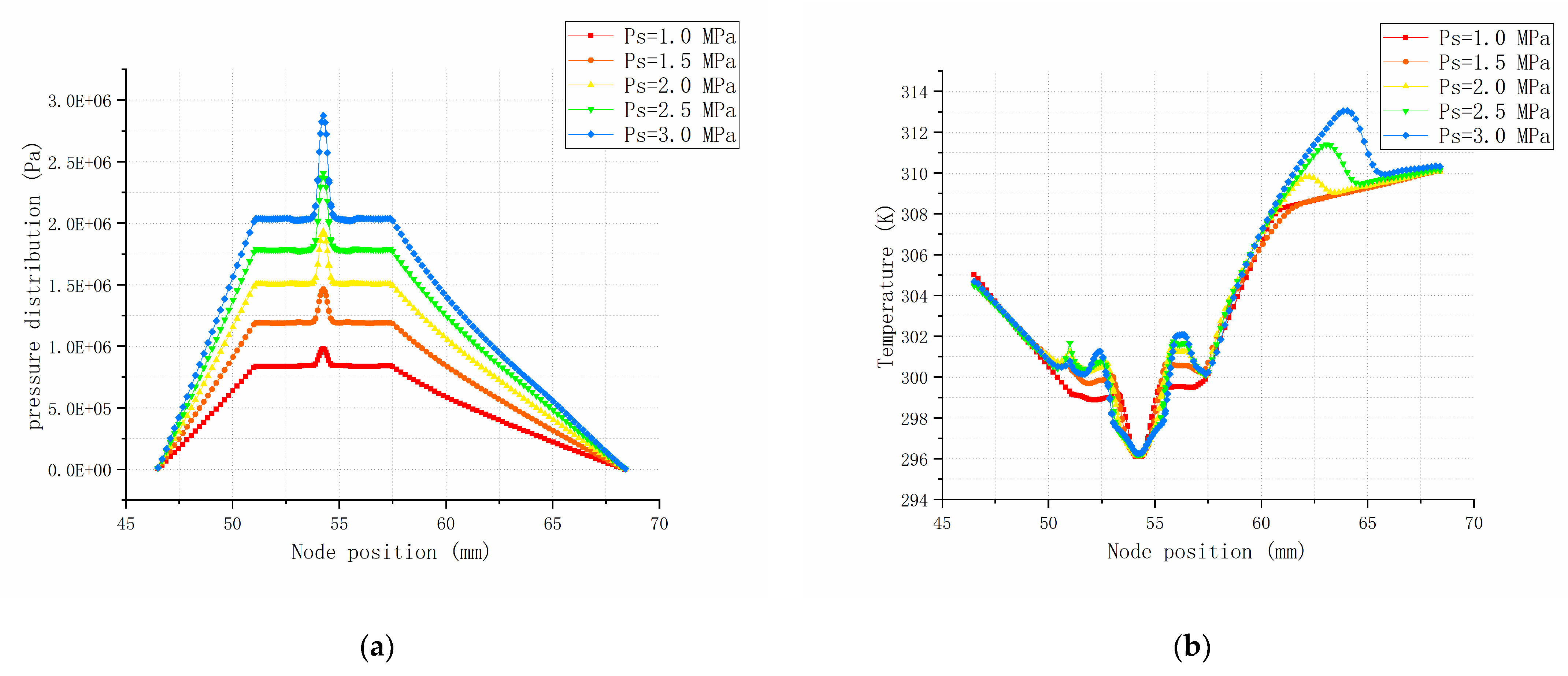
Figure 9.
Static pressure and temperature distribution of various supply pressure along the slice line A-A. (a) Pressure distribution at different supply pressure (Ps = 1~3 MPa); (b) Temperature distribution at different supply pressure (Ps = 1~3 MPa).
Figure 9.
Static pressure and temperature distribution of various supply pressure along the slice line A-A. (a) Pressure distribution at different supply pressure (Ps = 1~3 MPa); (b) Temperature distribution at different supply pressure (Ps = 1~3 MPa).

Figure 10.
Schematic diagram of turbulence intensity and velocity trace of orifice with different configurations. (a) Normal type; (b) Immersed hole and taper hole type; (c) Immersed hole type; (d) Taper hole type.
Figure 10.
Schematic diagram of turbulence intensity and velocity trace of orifice with different configurations. (a) Normal type; (b) Immersed hole and taper hole type; (c) Immersed hole type; (d) Taper hole type.

Figure 11.
Illustration of the experimental test rig and the hydrostatic bearing. (a) Experimental setup; (b) Oil supply on the bearing.
Figure 11.
Illustration of the experimental test rig and the hydrostatic bearing. (a) Experimental setup; (b) Oil supply on the bearing.

Figure 12.
Illustration of Sensor test point and stiffness test. (a) Hydrostatic thrust bearing and test points/locations; (b) Axial stiffness test of hydrostatic spindle.
Figure 12.
Illustration of Sensor test point and stiffness test. (a) Hydrostatic thrust bearing and test points/locations; (b) Axial stiffness test of hydrostatic spindle.

Figure 13.
Comparison of simulation and experimental data. (a) Variation trend of lubricating oil temperature at different rotating speeds; (b)The variation trend of the average bearing capacity in the oil chamber at different rotating speeds; (c) Variation trend of lubricating oil flow at different rotating speeds; (d) Variation trend of stiffness at different rotating speeds.


Publisher’s Note: MDPI stays neutral with regard to jurisdictional claims in published maps and institutional affiliations. |
© 2022 by the authors. Licensee MDPI, Basel, Switzerland. This article is an open access article distributed under the terms and conditions of the Creative Commons Attribution (CC BY) license (https://creativecommons.org/licenses/by/4.0/).
Share and Cite
MDPI and ACS Style
Shang, Y.; Cheng, K.; Ding, H.; Chen, S. Design of a Hydrostatic Spindle and Its Simulation Analysis with the Application to a High Precision Internal Grinding Machine. Machines 2022, 10, 127. https://doi.org/10.3390/machines10020127
AMA Style
Shang Y, Cheng K, Ding H, Chen S. Design of a Hydrostatic Spindle and Its Simulation Analysis with the Application to a High Precision Internal Grinding Machine. Machines. 2022; 10(2):127. https://doi.org/10.3390/machines10020127
Chicago/Turabian StyleShang, Youyun, Kai Cheng, Hui Ding, and Shijin Chen. 2022. "Design of a Hydrostatic Spindle and Its Simulation Analysis with the Application to a High Precision Internal Grinding Machine" Machines 10, no. 2: 127. https://doi.org/10.3390/machines10020127
Note that from the first issue of 2016, this journal uses article numbers instead of page numbers. See further details here.