
Design and Load Distribution Analysis of the Mismatched Cycloid-Pin Gear Pair in RV Speed Reducers


1
The State Key Laboratory of Mechanical Transmissions, Chongqing University, Chongqing 400044, China
2
School of Mechanical and Electrical Engineering, Soochow University, Suzhou 215021, China
*
Author to whom correspondence should be addressed.
Machines 2022, 10(8), 672; https://doi.org/10.3390/machines10080672
Submission received: 26 June 2022
/
Revised: 31 July 2022
/
Accepted: 5 August 2022
/
Published: 10 August 2022
(This article belongs to the Special Issue Design Methods for Mechanical and Industrial Innovation)
Abstract
:The current loaded tooth contact analysis of cycloid drives based on the assumption of theoretical positions of ring pins ignores the deviations caused by manufacturing errors and elastic deformations, which are not in agreement with reality. To fill this gap, an improved load distribution model of the mismatched cycloid-pin gear pair with ring pin position deviations is presented for a component-level analysis. Firstly, with the cycloid gear tooth profile geometry defined, the unloaded tooth contact analysis is applied as a pre-processor to determine the potential contact points, the gear backlash, and the rotation angle of the cycloid gear. Secondly, due to the statically indeterminate structure of the multi-tooth contact, a varying nonlinear contact stiffness is introduced to establish the relation between force and deformation. Then, the force and moment equilibrium equations with compatibility conditions are solved by using an iterative approach. With this, detailed parametric case studies are presented to verify the correctness of the proposed model by comparing it with those predicted by the current model and to demonstrate the influences of ring pin position deviations on the distributed load, contact stress, loaded transmission error, and instantaneous gear ratio of the mismatched cycloid-pin gear pair. This study provides a deeper investigation into the load distribution characteristics of the cycloid drive and therefore can be employed to assist in gear design.
1. Introduction
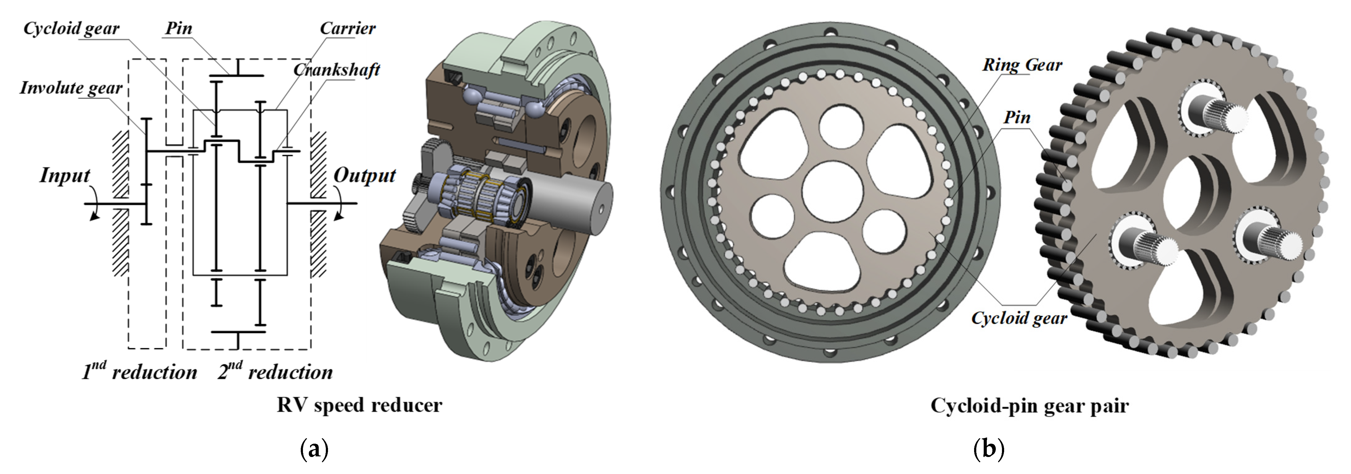
Nowadays, more attention has been paid to the application of cycloid drives in the areas of industrial robots, machine tools, and aerospace for precision transmission because of the advantages of a large reduction ratio, light weight, compact size, high transmission accuracy, and high shock-resistant ability [1,2,3]. The most representative one is a two-stage 2KV-type cycloid drive, known as the RV speed reduce, where RV is short for Rotate Vector, K stands for Central Gear, and V stands for Equal Velocity Mechanism. It consists of the involute planetary gear drive as the first reduction and the cycloid drive as the second reduction. Figure 1a illustrates its typical structure and main elements, including involute gears, two cycloid gears, the ring gear, several pins, crankshafts, bearings, and a combined carrier. The cycloid-pin gear pair can transfer large torques at small sizes with an accurate positioning precision and smooth motion. This advantage is subordinated to the multi-tooth contact characteristic for sharing the total torque continuously and to the use of two (sometimes three) cycloid gears reciprocally opposed by 180° to balance the centrifugal forces. Theoretically, all gear teeth meshes with corresponding pins are placed at equal intervals in pin grooves of the ring gear, and half of them are considered to transfer the torque at any instant [4], as shown in Figure 1b. However, the tooth profile modifications [5] and manufacturing and assembly errors [6] impede the ideal condition, leading to the uncertain changes of load distribution among the components of the RV speed reducer.
The cycloid-pin gear pair plays a vital role in fulfilling the mentioned specification but is more complex in design and more difficult to produce. Furthermore, a great demand is present in industry for design tools that can simultaneously reduce development time and lead to significant performance improvement. Load distribution analysis is a topic of broad literature and a useful tool to evaluate the performances of the gear drive, including the contact strength, transmission accuracy, and efficiency. The complex joint interactions and the continuously changing magnitudes and directions of forces occur among the components of the transmission system, making the load distribution analysis hard to conduct [7]. For the mechanics concepts, including the load distribution, contact stresses, and deformations in regard to components, the system-level analysis seems to not help very much. Therefore, in this study, taking consideration of a cycloid-pin gear pair to conduct a component-level analysis can provide a deeper understanding of component interactions and mismatched meshing caused by clearances or errors.
For providing some guidelines for the optimal design of cycloid drives [8], many re-studies in literature mainly focus on the geometrical design [9,10,11], kinematic and dynamic analysis [12,13,14,15], lubrication, and efficiency [16,17,18,19] of cycloid speed reducers. Several analytical load distribution models of cycloid drive at the component-level are developed, which are limited to an oversimplified description. Gorla et al. [20] presented a method to analyze the load distribution of the contact elements of a cycloid speed reducer, and the theoretical results are validated by an experiment. Malhotra et al. [21] calculated the loads distributed on components of the speed reducer under the hypotheses of perfect geometry and rigid contact. Li [22] developed an FEM program to analyze the tooth contact characteristics of the cycloid drive. Kumar et al. [7] developed a method to determine the elastic torsional stiffness of cycloid drives in the experimental studies. Lin et al. [14] presented a method for the kinematic error analysis and tolerance design of cycloidal gear reducers based on the discretization of the cycloidal tooth profile. Blagojevic et al. [23] developed an approximate approach for the multi-tooth contact analysis of a two-stage cycloid speed reducer. Li et al. [24,25] proposed an analytical method to calculate the contact stress and stiffness, the transmission error and its harmonic, and the gear ratio of cycloid drives, considering the influences of tooth profile modification and eccentric error. Sun et al. [26] conducted the tooth contact analysis on a new type of CBR reducer based on the method of the discrete point of tooth profiles. Wang et al. [2] established a multi-tooth contact model by dividing the contact area of tooth pairs into several differential elements. Hsieh et al. [13] presented a prediction method to estimate the stability and power loss for various designs of cycloid speed reducers by using the finite element method (FEM) implemented in the SolidWorks software. Li et al. [27,28] developed a multi-tooth contact model for cycloid drives applied in RV speed reducers, considering the manufacturing error effect. Xu et al. [29] developed a contact dynamic model of cycloid drives to analyze the load distribution, considering the cylindrical roller bearing effects. Zhang et al. [3] proposed a semi-analytical method for cycloid-pin gear pairs, considering both the tooth profile and longitudinal modifications for the load distribution analysis. Liu et al. [4] presented a novel approach based on error tooth surfaces to evaluate the transmission accuracy of a cycloid-pin gear pair. Csobán [30] investigated the impact of production failures on the kinematic features of cycloid drive by supposing different levels of production accuracy and tolerance zones created on different cog geometries. Yang et al. [6] studied the influence of manufacturing tolerances on torque ripples and backlash. Ivanović et al. [31] studied the effects of the geometrical parameters of a trochoidal gear on the gearing process, clearance height change, and pulsation of a drive moment. Bednarczyk [32] conducted a backlash distribution analysis considering the machining deviations of the elements and surfaces forming the output mechanism of the cycloidal gear reducer. Blagojević et al. [33] presented the stress state analysis of the cycloid disc by using numerical and experimental methods for the most critical case of the single meshing. The literature review reveals that the current loaded tooth contact analysis of cycloid drives based on the assumption of theoretical positions of ring pins ignores the deviations caused by contact deformations and manufacturing errors of the ring gear, including the ring pin radial position error and angular position error, as shown in the measurement report of the pin-grooves of a ring gear (See Figure 2), which are not in agreement with reality.
To fill this gap, an improved load distribution model of a mis-matched cycloid-pin gear pair is proposed with additional considerations of the ring pin position deviations and the contact deformation of the pin-groove pair at a component-level to calculate the load distributed among pins, the maximum contact stress, the loaded transmission error, and the variation of the instantaneous gear ratio through a mesh cycle. Additionally, the influence of the pin radial position error and angular position error on tooth contact is investigated and discussed. The study presented in this article is considered a very good and extensive approach to a better comprehension of cycloid drive technology.
2. Tooth Profile Geometry of Cycloid Gear
2.1. Tooth Profile Generation and Modification
The cycloid gear has an epitrochoid tooth profile, which is the envelope to the family of planar circular curves based on the enveloping method [9,11,34,35]. Three coordinate systems are defined for the tooth profile generation of cycloid gear, as shown in Figure 3. Two movable coordinate systems, and , and a fixed coordinate system, , stand for the ring pins, the gear disc, and the gearbox, respectively. The locus of point is a closed cycloid curve, and symbols and represent the clearances between the cycloid gear teeth and pins.
The equation of the cycloid gear tooth profile can be represented in :
where is the eccentricity, is the pin position radius, is the pin radius. is the angular parameter of the standard profile. Parameters and are the rotation angles with the relationship of . and stand for the numbers of ring pins and cycloid gear teeth with the relationship of .
The meshing equation is derived as:
To guarantee the reasonable clearances, four types of the tooth profile modification (TPM) [5] are proposed by means of changing and accordingly in Equation (1), as shown in Figure 3a,b, respectively. Hence, the general equation of four modified profiles can be rewritten as:
where and are the modification amounts. is the angular parameter of the modified profile.
2.2. Curvature Radius of the Cycloid Gear Tooth Profile
The curvature radius of the cycloid gear tooth profile with TPM can be represented as [25]:
where is the angular parameter.
3. Improved Load Distribution Modelling
The current load distribution model of the cycloid-pin gear pair is based on the assumption of the theoretical positions of ring pins [3,24,25,28,29]. This model lacks the ability to include the deviations effect accurately, which is caused by manufacturing errors and elastic deformations, and fails to agree with the practical property of the gear mesh process.
The overall methodology is based on the following assumptions to establish the improved load distribution model of the mismatched cycloid-pin gear pair:
- The model is discussed in the two-dimensional plane because the teeth are straight and parallel to the shaft axis.
- The model is established under the quasi-static condition, neglecting the inertia forces.
- Friction can be neglected to avoid the uncertainness about the Coulomb frictional coefficient.
- The influence of damaging will be negligible to avoid the uncertainness of the damaging when the stresses are beyond the allowable value.
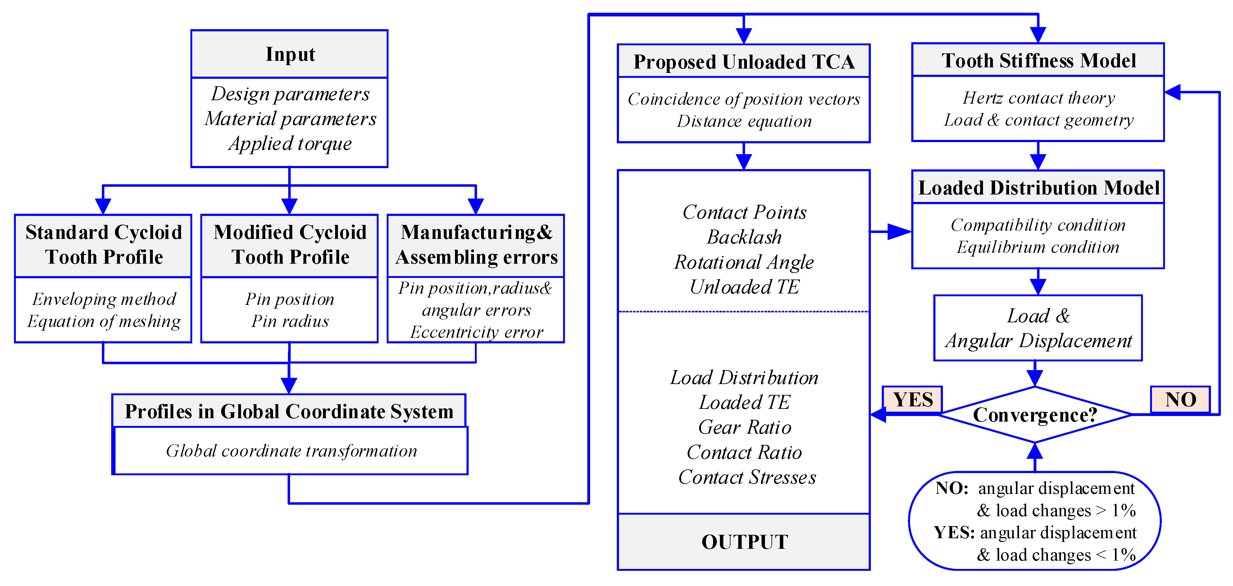
For an accurate analysis, an iteration procedure is proposed, as shown in Figure 4. The main steps are summarized as follows:
- Step 1
- Defining the modified tooth profile of the cycloid gear with the design parameters and the modifiaction ammounts.
- Step 2
- Applying the unloaded tooth contact analysis (TCA) to determine the meshing information when two contact conditions are satisfied by transferring the tooth and pin profiles into the fixed coordinate system.
- Step 3
- Determining the the initial guesses of angular parameters based on the geometrical and kinetic relationships; the values will be updated after every iteration. The system of nonlinear equations is then solved by the fsolve fuction provided in Matlab.
- Step 4
- Considering the meshing point as a linear spring with a contact stiffness along the line of action where the contact deformation of the pin-groove pair is introduced.
- Step 5
- The force and torque system equations are solved by the fsolve fuction provided in Matlab simultaneously by using an iterative technique after the initial load and angular displacement are given.
- Step 6
- After several iterations, load and angular displacement changes will converge within 1%, and then the iterative procedure will be terminated.
- Step 7
- Outputting the predicted rasults, including the distributed loads among pins, the contact stress, the transmission error, and the variation of the instantaneous gear ratio through a mesh cycle.
3.1. Unloaded Tooth Contact Analysis
As shown in Figure 5, two coordinate systems, and , stand for the pin-wheel and cycloid gear, respectively. A fixed coordinate system, , coinciding with is fixed. is the contact point.
Then, the position and normal vectors of pin profiles and can be expressed in :
where is the pin number, is the angle between two adjacent pins, is the unit vector, is the angular parameter on the pin profile, is the angular position error, is the radial position error, and is the radial error of the th pin.
The position vector and the unit normal vector can be expressed in :
where is the rotation angle of the cycloid disc, and
where is the eccentricity error.
To apply the unloaded TCA, the coincidence of position vectors and the collinearity of normal vectors should be satisfied. Therefore,
where ; therefore, in the vector equations, there are three independent nonlinear equations with four unknowns: , , , and . When the input crankshaft angle is given, other unknowns will be solved by the above equation system.
Then, the backlash and the rotational angle are represented as:
Note that the backlash angle is defined as the small amount of angular displacement, which is necessary for all the mating tooth pairs to contact each other so that the torque can be shared among them.
3.2. Initial Guesses Determination
To solve Equation (10), the initial guesses , , and are given based on the geometrical and kinetic relationships:
The above initial guesses corresponding to a crankshaft angle will be updated after every iteration. Then, the parameters , , and can be calculated in the unloaded TCA such that the meshing information within a mesh cycle can be determined.
3.3. Compatibility and Equilibrium Conditions
As shown in Figure 6, to determine contact points, the compatibility conditions can be expressed as:
where is the angular displacement caused by the contact deformation, is the variation of the rotation angle , and is the backlash, as mentioned above.
The static force and moment equations can be expressed as:
where , , and is the contact deformation of the th cycloid-pin gear pair. The arm of force can be represented as:
Then, the external torque can be rewritten as:
where is the mesh stiffness between the tooth and the pin, which is used to establish the force-displacement relationships.
3.4. Hertzian Contact Stiffness
In this study, the contact deformation between the pins and pin-grooves is considered in the Hertzian contact stiffness model. As shown in Figure 7, and represent the load distributed on pins and pin-grooves, which leads to the contact deformations and of the gear-pin pair and the pin-groove pair, respectively. Hence, the Hertzian contact stiffness on one cycloid-pin gear pair is defined as the applied force divided by the total displacement of the cycloid gear tooth getting close to the mating pin along the line of action, which can be represented as:
where and , which can be obtained as follows:
where is the width of cycloid gears, and is the angle between the directions of two forces. For the th cycloid-pin gear pair, , and are the contact widths, and are the equivalent elasticity moduli, and and are the equivalent radii of the curvature, which can be represented as:
where , , and stand for the elasticity modulus, Poisson’s ratio, and curvature radius, respectively. Subscripts p, c, and g stand for the pins, cycloid gear teeth, and pin-grooves, respecitvely.
3.5. Contact Stress, Loaded TE, and Gear Ratio
One of the major concerns during the gear design process is the contact strength examination of the cycloid-pin gear pair. Based on the Hertzian contact theory, the contact stress is considered as the maximum contact pressure among the contact area, which can be represented as:
where is the applied force, is the contact width, and is the contact length.
The loaded transmission error (TE) is the difference between the actual and theoretical rotation angle, and , of the cycloid gear disc, which is expressed as:
where and .
The instantaneous gear ratio is the ratio between the output and input angular velocity, while the ideal gear ratio is a constant value which equals the cycloid gear tooth number. Then, the instantaneous gear ratio can be represented as:
where and represent increments of the actual output and input rotation angles.
4. Analysis Results and Discussion
In this section, the proposed model is implemented by a computer program using MATLAB software. The basic design parameters of an example cycloid-pin gear pair are listed in Table 1. There is an assumption that the material of the cycloid gear and that of the pins are the same, which is the steel with a Poisson’s ratio = 0.3 and a Young’s modulus E = 206 GPa. The applied torque is set as 250 Nm.
4.1. Comparison and Verification
In order to verify the correctness and availability of the proposed model, and also to demonstrate the effects of the contact deformation of the pin-groove pair without a loss of generality, four cases are analyzed and compared with the current model. The signs indicate whether it is taken consideration in this case (√) or not (×), as shown in Table 2.
Figure 8 shows the predicted load distributed among pins and pin-grooves at 0°, 60°, 120°, and 180° crankshaft angles of four cases for comparison. It can be seen that, for Case 3 and Case 4, without considering the TPM, as expected, almost half of the pins (20) participate in the torque transmission, and the loads on the teeth change periodically within a mesh cycle. For Case 1 and Case 2, with TPM, the number of pins mating with the corresponding teeth decreases dramatically due to the existence of the backlash, leading to an increase in the maximum load. By comparing Case 1 and Case 3 with Case 2 and Case 4, respectively, the result obtained by the proposed model is in accordance with that predicted by the current model with respect to the pin numbers where the load is distributed, although some discrepancies with respect to the magnitude of the load are observed due to the contact deformation of the pin-groove pair.
Figure 9 shows the variations of the time-varying contact stress over the tooth profile corresponding to pin number 20 for the four cases. It can be noted that the contact length decreases dramatically when the TPM is considered in Case 1 and Case 2. Comparing Case 1 with Case 3, the maximum contact stress of the cycloid-pin pairs increases from about 868 MPa to 1017 MPa due to the increasing loads on a single tooth pair, as shown in Figure 8. Because of the contact deformation of pin-groove pairs, for Case 2 and Case 4, the magnitudes of maximum contact stress are a little bit higher than those for Case 1 and Case 3.
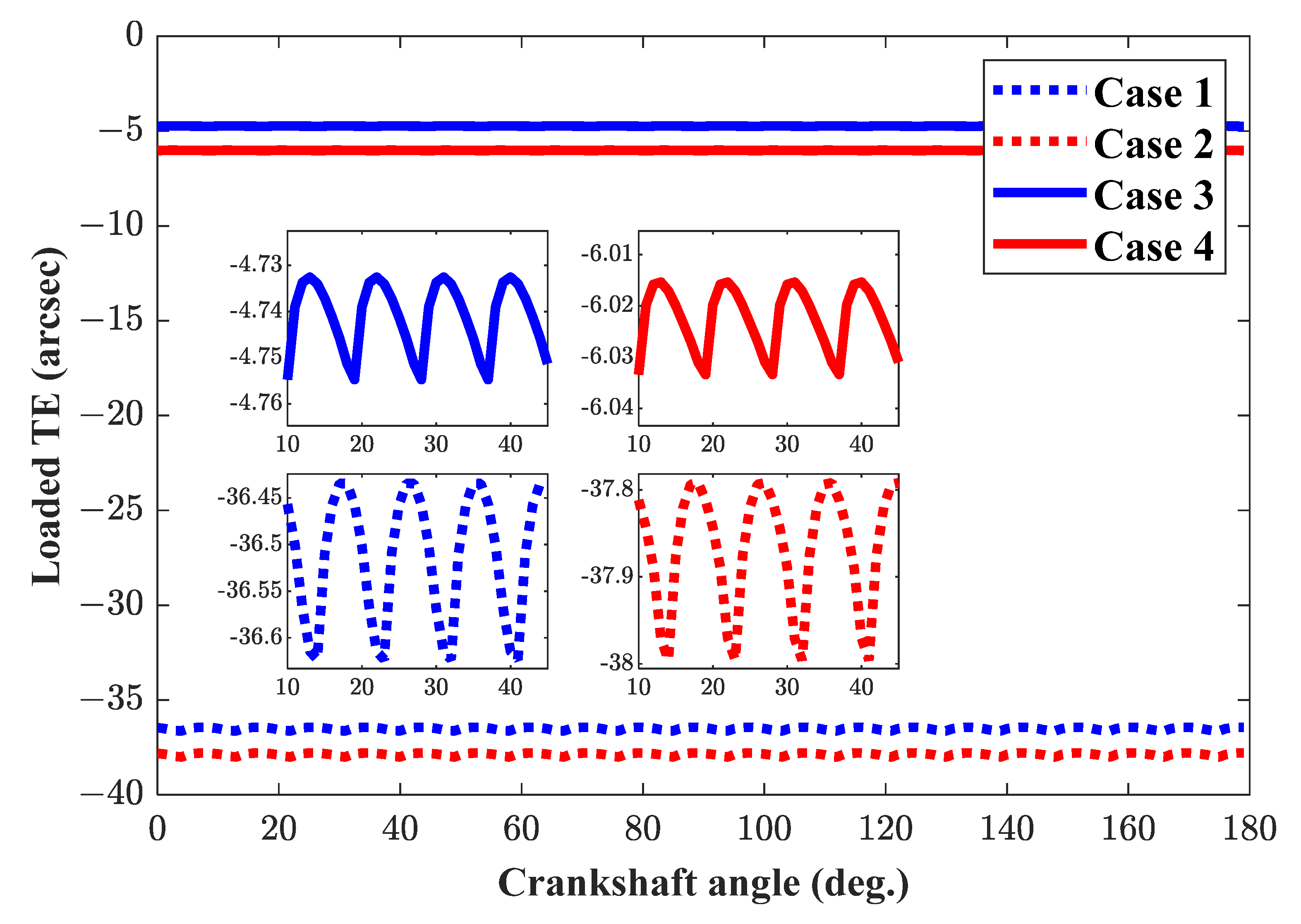
Figure 10 shows the comparison of the loaded TE within one mesh circle for four cases. It is observed that, for four cases, the loaded TE curves are periodical, continuous, quasi-sinusoid, and parabolic curves. For Case 3 and Case 4, without TPM, the mean and peak-to-peak values of the loaded TE are −4.745 arc seconds, 0.022 arc seconds, −6.023 arc seconds, and 0.018 arc seconds, respectively. When the TPM is present for Case 1 and Case 2, both the mean and peak-to-peak values of the loaded TE increase due to the increase in meshing clearances, as expected. For Case 2 and Case 4, considering the contact deformation of pin-groove pairs, the absolute mean values and magnitudes are larger than those for Case 1 and Case 3. It can be concluded that the comparison results obtained by the proposed model show a good agreement with those predicted by the current model, which could verify the correctness of the proposed model. The effects of the contact deformation of pin-groove pairs on the distributed load, contact stress, and loaded TE can also be seen, which should be taken seriously in the design stage.
4.2. Effect of the Position Deviations of Ring Pins
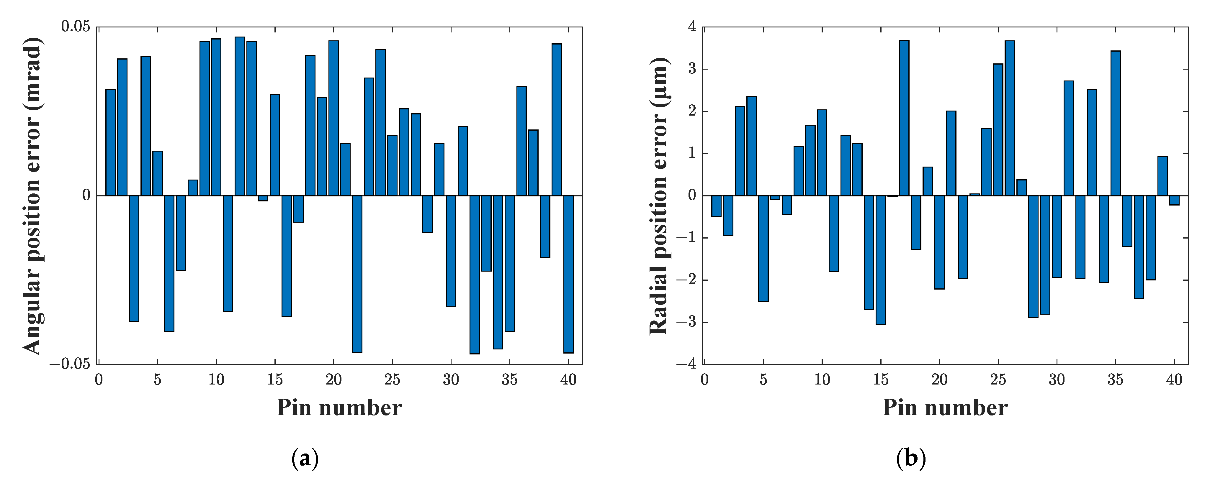
In this section, to demonstrate the effects of the position deviations of ring pins on the load distributed on teeth and pins, the contact stress, the loaded TE, and the instantaneous gear ratio, three cases using the same example are considered and predicted by the proposed model. Case 1 is under ideal conditions without TPM or any errors. Case 2 and Case 3 both involve a mismatched gear pair. For Case 2, only the TPM is considered, while for Case 3, both the TPM and position deviations of the ring pins are considered. Without a loss of generality, the position errors of the ring pins are given randomly, with the ranges of ±0.05 mrad for angular position errors and ±4 μm for radial position errors, which are shown in Figure 11.
Figure 12 shows the comparison of the load distribution among tooth pairs at 0°, 60°, 120°, and 180° crankshaft angles. It can be noted that, for Case 1 and Case 2, the variations of the load distributed on the adjacent pins are gentle and smooth. However, for Case 3, large discrepancies are observed; the maximum value increases to about 1722 N on pin number 11 at a 60°crankshaft angle, where the pitting failure has already happened in actual situations. There are the irregular and abrupt changes in the load distribution, which can be explained by the fact that the random position errors on all pins cause more reductions as well as abrupt changes in the number of mating tooth pairs.
Figure 13 shows the effects of the random position errors on the time-varying Hertzian contact stress on all the pins and also on the corresponding pin-grooves. It can be seen that, for Case 3, the variations of the Hertzian contact stress show many abrupt changes, and the highest magnitude is on pin number 22. Comparing Figure 13a with Figure 13b, due to concavo-convex contact characteristic, the maximum contact stress between the pins and the corresponding teeth (1887 MPa) is much higher than that between the pins and the corresponding pin-grooves (44 MPa), which may exceed the allowable stress of the material used, leading to pitting failure on the gear tooth surfaces. In the improved model, the influence of damaging will be negligible. With this assumption, the proposed model can be used to predict whether the failure happens with the stress values to avoid the uncertainness of the damage when the stress is beyond the allowable value.
Figure 14 shows the comparisons of the loaded TE for three cases. It is observed that, for Case 1 and Case 2, the loaded TE shows a periodical change as the crankshaft rotates. The mean values are −6.023 arc seconds and −37.89 arc seconds, as expected. Their peak-to-peak values are 0.018 arc seconds and 0.21 arc-seconds. For Case 3, the loaded TE is an irregular curve, and both the mean and peak-to-peak values change significantly to −38.26 arc seconds and 5.83 arc-seconds due to the random angular position errors and radial position errors. It can be concluded that the position deviations of ring pins have a significant influence on the loaded TE of the cycloid-pin gear pair, leading in turn to instability and a reduction in the positioning accuracy of the RV speed reducers.
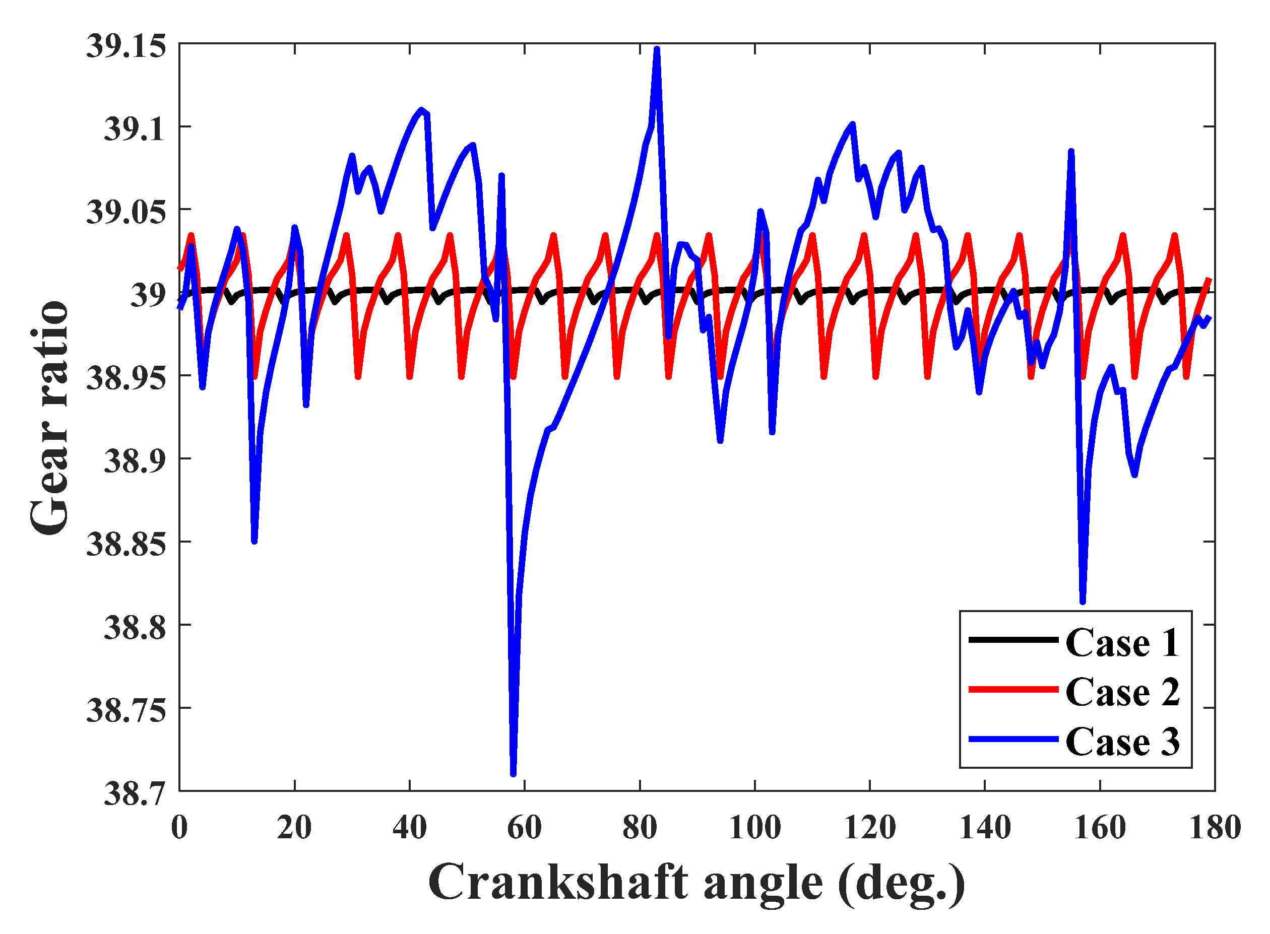
Figure 15 shows the comparisons of the instantaneous gear ratio for three cases. Comparing Case 3 with Case 2, a large irregular fluctuation of the instantaneous gear ratio is observed. The peak-to-peak value ranges from 8% to 44 % of the ideal gear ratio. Note that the fluctuation of the instantaneous gear ratio is the main reason for the torque ripple, which will lead to the harmonic resonance of the industrial robot. To avoid this, the position deviations of ring pins should be confined to a certain extent in the design process.
Figure 16 shows the comparisons of the number of tooth pairs in contact for three cases as the crankshaft rotates. Due to the TPM and contact deformation under loading conditions, for Case 1 and Case 2, they alternate periodically between 19 and 20 and 9 and 10 with the period of a 9° crankshaft angle, respectively. For Case 3, the number of tooth pairs in contact varies irregularly, and its minimum value reaches 4, which will lead to a larger contact stress, at risk of pitting failure. This can be explained by the fact that the random angular position errors and radial position errors change the clearances between all the tooth pairs. Therefore, due to their significant influence, the position deviations of ring pins should be taken seriously in the predicted model and the design stage.
5. Conclusions
In this study, an improved load distribution model of the mismatched cycloid-pin gear pairs is proposed. The proposed model has the ability to analyze the gear pairs with the position deviations of ring pins. The proposed model is applied for the investigation of the influence of the random angular and radial position errors of the ring pins on the distributed load, maximum contact stress, loaded transmission error, and instantaneous gear ratio. On the basis of the obtained results, the following conclusions can be made:
- 1.
- In order to improve the precision of the prediction model, the contact deformation of the pin-groove pairs under the cycloid drive design stage should be considered indispensably, which is verified by the comparison with those obtained by the current model. It has some effects on the maximum contact stress and the mean and peak-to-peak values of the loaded TE.
- 2.
- The obtained results show the necessity of the consideration of the tooth profile modification in the design and analysis of the cycloid-pin gear pair. It was observed to significantly influence the distributed load, contact stress, loaded TE, and real gear ratio of the cycloid drive. The number of contacting pins decreases from 20 to 9. The stress increases to 149 MPa. The absolute mean values of the loaded TE increase by about 30 arc seconds when the tooth profile modification is present.
- 3.
- Even minute random angular and radial position errors of the ring pins with the ranges of ±0.05 mrad and ±4 μm of the pinion have considerable effects on the tooth contact parameters. Large discrepancies are observed, the maximum contact stress reaches 1887 MPa beyond the strength limit, the peak-to-peak values of the loaded TE increase from 0.21 arc seconds to 5.38 arc seconds, and the peak-to-peak value of the gear ratio increases to 44 % of the ideal gear ratio. The irregular change of meshing clearances caused by the combined position error has a very strong influence on the tooth contact, which will worsen the contact strength, transmission accuracy, and torque ripple of the RV speed reducer.
This study provides some guidance for the analysis, design, and optimization of cycloid-pin gear pairs, and it will be considered as a very good and extensive approach to a better comprehension of cycloid drive technology.
Author Contributions
Conceptualization, X.L. and L.S.; methodology, X.L.; software, L.T.; writing—original draft preparation, X.L. and L.T.; writing—review and editing, H.H.; visualization, L.T.; supervision, L.S.; project administration, X.L.; funding acquisition, X.L. All authors have read and agreed to the published version of the manuscript.
Funding
This research was funded by the Foundation of the State Key Laboratory of Mechanical Transmissions (No. SKLMT-MSKFKT-202007), the National Natural Science Foundation of China (No. 52005354), and the Natural Science Foundation of Jiangsu Province (No. BK20190824).
Institutional Review Board Statement
Not applicable.
Informed Consent Statement
Not applicable.
Data Availability Statement
Not applicable.
Acknowledgments
The authors are grateful for the support from the Foundation of the State Key Laboratory of Mechanical Transmissions (No. SKLMT-MSKFKT-202007), the National Natural Science Foundation of China (No. 52005354), and the Natural Science Foundation of Jiangsu Province (No. BK20190824). The authors are grateful to the other participants of the project for their cooperation.
Conflicts of Interest
The authors declare that there is no conflict of interest regarding the publication of this paper.
References
- Sensinger, J.W. Unified approach to cycloid drive profile, stress, and efficiency optimization. J. Mech. Des. 2010, 132, 024503. [Google Scholar] [CrossRef]
- Wang, H.; Shi, Z.Y.; Yu, B.; Xu, H. Transmission performance analysis of RV reducers influenced by profile modification and load. Appl. Sci. 2019, 9, 4099. [Google Scholar] [CrossRef] [Green Version]
- Zhang, T.; Li, X.; Wang, Y.; Sun, L. A semi-analytical load distribution model for cycloid drives with tooth profile and longitudinal modifications. Appl. Sci. 2020, 10, 4859. [Google Scholar] [CrossRef]
- Liu, C.; Shi, W.; Xu, L.; Liu, K. A novel approach to calculating the transmission accuracy of a cycloid-pin gear pair based on error tooth surfaces. Appl. Sci. 2021, 11, 8671. [Google Scholar] [CrossRef]
- Lin, W.S.; Shih, Y.P.; Lee, J.J. Design of a two-stage cycloidal gear reducer with tooth modifications. Mech. Mach. Theory 2014, 79, 184–197. [Google Scholar] [CrossRef]
- Yang, D.C.H.; Blanche, J.G. Design and application guidelines for cycloid drives with machining tolerances. Mech. Mach. Theory 1990, 25, 487–501. [Google Scholar] [CrossRef]
- Kumar, N.; Kosse, V.; Oloyede, A. A new method to estimate effective elastic torsional compliance of single-stage cycloidal drives. Mech. Mach. Theory 2016, 105, 185–198. [Google Scholar] [CrossRef]
- Do, T.P.; Ziegler, P.; Eberhard, P. Review on contact simulation of beveloid and cycloid gears and application of a modern approach to treat deformations. Math. Comput. Model. Dyn. Syst. 2015, 21, 359–388. [Google Scholar] [CrossRef]
- Chen, B.; Zhong, H.; Liu, J.; Li, C.; Fang, T. Generation and investigation of a new cycloid drive with double contact. Mech. Mach. Theory 2012, 49, 270–283. [Google Scholar] [CrossRef]
- Demenego, A.; Vecchiato, D.; Litvin, F.L.; Nervegna, N.; Manco, S. Design and simulation of meshing of a cycloidal pump. Mech. Mach. Theory 2002, 37, 311–332. [Google Scholar] [CrossRef]
- Litvin, F.L.; Feng, P.H. Computerized design and generation of cycloidal gearings. Mech. Mach. Theory 1996, 31, 891–911. [Google Scholar] [CrossRef]
- Dion, J.L.; Pawelski, Z.; Chianca, V.; Zdziennicki, Z.; Peyret, N.; Uszpolewicz, G.; Ormezowski, J.; Mitukiewicz, G.; Lelasseux, X. Theoretical and experimental study for an improved cycloid drive model. J. Appl. Mech. 2019, 87, 011002. [Google Scholar] [CrossRef]
- Hsieh, C.F.; Fuentes-Aznar, A. Performance prediction method of cycloidal speed reducers. J. Braz. Soc. Mech. Sci. Eng. 2019, 41, 186. [Google Scholar] [CrossRef]
- Lin, K.S.; Chan, K.Y.; Lee, J.J. Kinematic error analysis and tolerance allocation of cycloidal gear reducers. Mech. Mach. Theory 2018, 124, 73–91. [Google Scholar] [CrossRef]
- Wikło, M.; Król, R.; Olejarczyk, K.; Kołodziejczyk, K. Output torque ripple for a cycloidal gear train. Proc. Inst. Mech. Eng. Part C J. Mech. Eng. Sci. 2019, 233, 7270–7281. [Google Scholar] [CrossRef]
- Ivanovic, L.; Mackic, T.; Stojanovic, B. Analysis of the instantaneous friction coefficient of the trochoidal gear pair. J. Balk. Tribol. Assoc. 2016, 22, 281–293. [Google Scholar]
- Mackic, T.; Blagojevic, M.; Babic, Z.; Kostic, N. Influence of design parameters on cyclo drive efficiency. J. Balk. Tribol. Assoc. 2013, 19, 497–507. [Google Scholar]
- Mihailidis, A.; Athanasopoulos, E.; Agouridas, K. EHL film thickness and load dependent power loss of cycloid reducers. Proc. Inst. Mech. Eng. Part C J. Mech. Eng. Sci. 2015, 230, 0954406215612815. [Google Scholar] [CrossRef]
- Olejarczyk, K.; Wikło, M.; Kołodziejczyk, K. The cycloidal gearbox efficiency for different types of bearings—Sleeves vs. needle bearings. Proc. Inst. Mech. Eng. Part C J. Mech. Eng. Sci. 2019, 233, 7401–7411. [Google Scholar] [CrossRef]
- Gorla, C.; Davoli, P.; Rosa, F.; Longoni, C.; Chiozzi, F.; Samarani, A. Theoretical and experimental analysis of a cycloidal speed reducer. J. Mech. Des. 2008, 130, 112604. [Google Scholar] [CrossRef]
- Malhotra, S.K.; Parameswaran, M.A. Analysis of a cycloid speed reducer. Mech. Mach. Theory 1983, 18, 491–499. [Google Scholar] [CrossRef]
- Li, S. Design and strength analysis methods of the trochoidal gear reducers. Mech. Mach. Theory 2014, 81, 140–154. [Google Scholar] [CrossRef]
- Blagojevic, M.; Marjanovic, N.; Djordjevic, Z.; Stojanovic, B.; Disic, A. A new design of a two-stage cycloidal speed reducer. J. Mech. Des. 2011, 133, 085001. [Google Scholar] [CrossRef]
- Li, X.; Chen, B.K.; Wang, Y.W.; Lim, T.C. Mesh stiffness calculation of cycloid-pin gear pair with tooth profile modification and eccentricity error. J. Cent. South Univ. 2018, 25, 1717–1731. [Google Scholar] [CrossRef]
- Li, X.; Li, C.Y.; Wang, Y.W.; Chen, B.K.; Lim, T.C. Analysis of a cycloid speed reducer considering tooth profile modification and clearance-fit output mechanism. J. Mech. Des. 2017, 139, 12. [Google Scholar] [CrossRef]
- Sun, X.; Han, L.; Wang, J. Design and transmission error analysis of cbr reducer. J. Mech. Des. 2019, 141, 082301. [Google Scholar] [CrossRef]
- Li, T.; An, X.; Deng, X.; Li, J.; Li, Y. A new tooth profile modification method of cycloidal gears in precision reducers for robots. Appl. Sci. 2020, 10, 1266. [Google Scholar] [CrossRef] [Green Version]
- Li, T.; Tian, M.; Xu, H.; Deng, X.; Su, J. Meshing contact analysis of cycloidal-pin gear in RV reducer considering the influence of manufacturing error. J. Braz. Soc. Mech. Sci. Eng. 2020, 42, 133. [Google Scholar] [CrossRef]
- Xu, L.X.; Chen, B.K.; Li, C.Y. Dynamic modelling and contact analysis of bearing-cycloid-pinwheel transmission mechanisms used in joint rotate vector reducers. Mech. Mach. Theory 2019, 137, 432–458. [Google Scholar] [CrossRef]
- Csobán, A. Impacts of a profile failure of the cycloidal drive of a planetary gear on transmission gear. Lubricants 2021, 9, 71. [Google Scholar] [CrossRef]
- Ivanović, L.; Devedžić, G.; Ćuković, S.; Mirić, N. Modeling of the meshing of trochoidal profiles with clearances. J. Mech. Des. 2012, 134, 041003. [Google Scholar] [CrossRef]
- Bednarczyk, S. Analysis of the cycloidal reducer output mechanism while taking into account machining deviations. Proc. Inst. Mech. Eng. Part C J. Mech. Eng. Sci. 2021, 235, 7299–7313. [Google Scholar] [CrossRef]
- Blagojevic, M.; Marjanovic, N.; Djordjevic, Z.; Stojanovic, B.; Marjanovic, V.; Vujanac, R.; Disic, A. Numerical and experimental analysis of the cycloid disc stress state. Teh. Vjesn. 2014, 21, 377–382. [Google Scholar]
- Hwang, Y.W.; Hsieh, C.F. Geometry design and analysis for trochoidal-type speed reducers: With conjugate envelopes. Trans. Can. Soc. Mech. Eng. 2006, 30, 261–278. [Google Scholar] [CrossRef]
- Litvin, F.L.; Fuentes, A. Gear Geometry and Applied Theory, 2nd ed.; Cambridge University Press: New York, NY, USA, 2004; pp. 350–354. [Google Scholar]
Figure 1.
(a) The schematic view of an RV speed reducer; (b) the 3D model of a cycloid-pin gear pair.
Figure 1.
(a) The schematic view of an RV speed reducer; (b) the 3D model of a cycloid-pin gear pair.

Figure 2.
The manufacturing errors of the ring gear: (a) the pin-groove radial error; (b) the pin-groove position error.
Figure 2.
The manufacturing errors of the ring gear: (a) the pin-groove radial error; (b) the pin-groove position error.

Figure 3.
Coordinate systems for the tooth profile modification of cycloid gears: (a) pin radius modification; (b) pin position modification.
Figure 3.
Coordinate systems for the tooth profile modification of cycloid gears: (a) pin radius modification; (b) pin position modification.

Figure 4.
Flowchart of the load distribution analysis for the cycloid-pin gear pair.

Figure 5.
Coordinate systems for the unloaded TCA.

Figure 6.
Compatibility and equilibrium conditions.

Figure 7.
Hertzian contact stiffness mechanics model of the cycloid-pin gear pair.

Figure 8.
Comparison of the loads distributed among pins and pin-grooves at (a) 0°, (b) 60°, (c) 120°, and (d) 180° crankshaft angles for four cases.
Figure 8.
Comparison of the loads distributed among pins and pin-grooves at (a) 0°, (b) 60°, (c) 120°, and (d) 180° crankshaft angles for four cases.

Figure 9.
Comparison of the contact stress on pin number 20 within one mesh circle for four cases.

Figure 10.
Comparison of the loaded transmission error within one mesh circle for four cases.

Figure 11.
The random (a) angular and (b) radial position errors of all ring pins.

Figure 12.
Comparison of the load distribution on ring pins at (a) 0°, (b) 60°, (c) 120°, and (d) 180° crankshaft angles for three cases.
Figure 12.
Comparison of the load distribution on ring pins at (a) 0°, (b) 60°, (c) 120°, and (d) 180° crankshaft angles for three cases.


Figure 13.
Comparison of the time-varying Hertzian contact stress on all (a) the pins and (b) the corresponding pin-grooves.
Figure 13.
Comparison of the time-varying Hertzian contact stress on all (a) the pins and (b) the corresponding pin-grooves.

Figure 14.
Comparisons of the loaded TE for three cases.

Figure 15.
Comparisons of the instantaneous gear ratio for three cases.

Figure 16.
Comparisons of the number of tooth pairs in contact for three cases.


Table 1.
Major design parameters for the example cycloid-pin gear pair.
| Parameters | Descriptions | Values |
|---|---|---|
| Tooth number | 39 | |
| Pin number | 40 | |
| Pin position radius | 82 mm | |
| Pin radius | 3.5 mm | |
| Pin-groove radius | 3.505 mm | |
| Eccentricity | 1.5 mm | |
| Cycloid gear width | 12 mm | |
| 0 μm | ||
| 8 μm | ||
| Eccentricity error | 0 μm | |
| Radial error | 0 μm |
Table 2.
Consideration judgment of TPM and for four cases.
| Case 1 | Case 2 | Case 3 | Case 4 | |
|---|---|---|---|---|
| TPM | √ | √ | × | × |
| × | √ | × | √ |
Publisher’s Note: MDPI stays neutral with regard to jurisdictional claims in published maps and institutional affiliations. |
© 2022 by the authors. Licensee MDPI, Basel, Switzerland. This article is an open access article distributed under the terms and conditions of the Creative Commons Attribution (CC BY) license (https://creativecommons.org/licenses/by/4.0/).
Share and Cite
MDPI and ACS Style
Li, X.; Tang, L.; He, H.; Sun, L. Design and Load Distribution Analysis of the Mismatched Cycloid-Pin Gear Pair in RV Speed Reducers. Machines 2022, 10, 672. https://doi.org/10.3390/machines10080672
AMA Style
Li X, Tang L, He H, Sun L. Design and Load Distribution Analysis of the Mismatched Cycloid-Pin Gear Pair in RV Speed Reducers. Machines. 2022; 10(8):672. https://doi.org/10.3390/machines10080672
Chicago/Turabian StyleLi, Xuan, Linggao Tang, Haidong He, and Lining Sun. 2022. "Design and Load Distribution Analysis of the Mismatched Cycloid-Pin Gear Pair in RV Speed Reducers" Machines 10, no. 8: 672. https://doi.org/10.3390/machines10080672
Note that from the first issue of 2016, this journal uses article numbers instead of page numbers. See further details here.