

Coordinated Control Strategy of Electro-Hydraulic Composite Braking Torque for the Distributed Electric Vehicles

1
School of Vehicle and Traffic Engineering, Henan University of Science and Technology, Luoyang 471000, China
2
Ningbo Shenglong Group Co., Ltd., Ningbo 315100, China
*
Author to whom correspondence should be addressed.
Machines 2022, 10(12), 1235; https://doi.org/10.3390/machines10121235
Submission received: 12 November 2022
/
Revised: 12 December 2022
/
Accepted: 14 December 2022
/
Published: 16 December 2022
(This article belongs to the Topic Vehicle Dynamics and Control)
Abstract
:The difference in response to electric and hydraulic braking causes sudden changes in braking torque during braking mode switching. An electro-hydraulic composite braking system’s dynamic torque coordination control strategy is proposed under braking mode switching conditions. By establishing the dynamic response model of the electro-hydraulic braking system (EHB), the key factors affecting the response speed of the EHB are analyzed, and the dynamic fuzzy controller for the pressure regulation of the brake wheel cylinder is designed. At the same time, the nonlinearity and hysteresis in the hydraulic braking process are considered, as well as electrical brake response overshoots. The electric brake response model is established, and the PID controller with feedforward feedback is designed to control the motor to adjust the inertia overpressure or lag pressure deficiency in the hydraulic braking process. Finally, the simulation verification is carried out; the results show that the proposed strategy can increase the hydraulic brake response speed by 25.4%, the impact degree of the vehicle is not more than 6.25 GB, and the hydraulic steady state error does not exceed 2.3%, which improves the vehicle ride comfort under braking mode switching.
1. Introduction
Battery electric vehicles have become an important research object of new energy vehicles because of their energy conservation, environment protection, and non-pollution. The electric–hydraulic composite braking system of battery electric vehicles comprises an electro-hydraulic braking system (EHB) and a regenerative braking system, which can realize various braking modes, such as single hydraulic braking, single motor braking, and electric–hydraulic composite braking [1,2,3]. It not only can discover the recovery of braking energy and improve the vehicle driving mileage but also ensure the braking stability and efficiency in the braking process. Due to the difference in the response of electric braking and hydraulic braking in the process of electric–hydraulic composite braking, the wheel output brake torque of electric vehicles is abrupt in the process of braking mode switching, which has a direct impact on the service life of the components and the riding comfort of the vehicle [4,5].
To solve the problem of that sudden change of braking torque caused by the braking mode switching process, Zheng et al. [6] used the filtering algorithm to divide the braking force change frequency into high frequency and low frequency. When the braking force change rate is at high frequency, motor braking is adopted, and hydraulic braking is adopted at low frequency, thus making full use of the dynamic response characteristics of the electro-hydraulic braking system to improve the ride comfort of the vehicle during braking. Pan et al. [7] used the hidden Markov model to conduct adaptive learning in the brake pedal operation training library and proposed a recognition control function to identify the braking behavior, which controls the motor and PWM parameters to adjust the pressure of the brake wheel cylinder and realize the rapid response for the pressure of the brake wheel cylinder. Aksjonov Andrei et al. [8] used the electro-hydraulic braking test bench to simulate the hydraulic braking circuit’s natural pressure variation in the automobile braking process. They designed a series of controllers by using the fuzzy control algorithm to verify the excellent control ability of fuzzy control for nonlinear systems. Therefore, the control of hydraulic braking systems has great potential in the future. Yu et al. [9] proposed a double closed-loop feedback control method by using electric braking force compensation to correct hydraulic braking force, which used the electric braking force to restore the hydraulic braking force to reduce the impact caused by the braking mode switch. Yang et al. [10] took the pure hydraulic brake as the reference model and realized the precise control of the brake wheel cylinder pressure by using the PID and fuzzy control combined control algorithm. At the same time, because the electric brake has fast response characteristics, it is used to compensate for the hydraulic braking force, thereby reducing the torque fluctuation during the braking mode switching. Wang et al. [11] combined electric and hydraulic brake response characteristics, and the inconsistent impact sensation in the braking process was analyzed. By designing a brake induction consistency controller, and based on the multi-objective optimization algorithm, a method of electric braking force and hydraulic braking force distribution is proposed to make up for the difference in electro-hydraulic braking response and improve the smoothness of automobile driving. Zhang et al. [12] proposed a motor control method for the highly dynamic braking process, which used synovial gap compensation and doubled closed-loop PID compensation to control the motor to reduce the transmission system’s impact on the electric braking under emergency braking conditions. It improves the response speed of electric brakes in braking mode switching, and the braking stability of automobiles is improved. Kumar et al. [13] proposed a cooperative braking mode of electric braking and mechanical braking for the unique structure of hybrid electric vehicles, considered the response characteristics of the electric braking system and mechanical braking systems, and determined the new distribution relationship between electric braking and mechanical braking. After conducting a simulation verification for urban working conditions, they determined that it improved ride smoothness during braking.
The above research is mainly adjusted for the braking force distribution method and used the electric braking response speed characteristics to compensate for hydraulic brake, reducing torque fluctuations during braking. However, they need to consider the problem of lack of adjustment and compensation ability under electric brake saturation. The strategies developed mainly focus on improving the response speed of hydraulic braking from the algorithm. The influence of hydraulic structural parameters on the system cannot be ignored [14,15,16].
Therefore, this paper takes an electric vehicle driven by an in-wheel motor as the research object. Fully considering the dynamic process of hydraulic braking response, the dynamic response model of the electro-hydraulic brake system (EHB) was established to analyze the influence of the critical factors on EHB response speed, discover the law of influence on the EHB response speed, and determine the parameters of EHB model. Then the pressure of the brake wheel cylinder is precisely controlled by a fuzzy algorithm, through calculating the brake wheel cylinder pressure fluctuation range to determine the reserve electric braking torque values. A feedforward–feedback PID controller is designed to control the motor, which can prevent the inertia overvoltage and hysteresis under pressure in hydraulic braking. Finally, the effectiveness of the strategy is verified by Simulink–Carsim–AMESim co-simulation.
The content of each section of this paper and the logical relationship between them are as follows.
In Section 1, the problems to be studied are put forward, the research status is analyzed, and the corresponding control strategy is put forward.
In Section 2, aiming at the proposed control strategy, on the one hand, a vehicle model is established to provide experimental basis for the later simulation verification and judgment of vehicle ride comfort during braking. On the other hand, the dynamic change model of single wheel electro-hydraulic composite braking force is established to reflect better the braking force change of the electro-hydraulic composite braking system in the process of braking mode switching.
In Section 3, the most crucial electro-hydraulic composite braking system in the braking process is modeled. Firstly, the in-wheel motor is modeled after considering the factors of rational motor operating characteristics and braking energy recovery. Secondly, AMESim is used to build a hydraulic brake simulation platform to analyze the changes in the EHB braking process and derive the response motion equation of the corresponding components. Finally, the electro-hydraulic composite braking system model was simulated and solved to explore the root cause of the difference in electro-hydraulic braking response. Furthermore, the conjecture that the improvement of structural parameters can improve the response speed of hydraulic braking is proposed, and the corresponding control algorithm is determined for different braking system response characteristics.
Section 4 demonstrates the hypothesis that the improvement of structural parameters can improve the hydraulic brake response speed and determine the value range of the input and output of the hydraulic brake controller.
In Section 5, the control algorithm proposed in Section 2 is used to design the feedforward–feedback PID controller to control the electric braking system and the fuzzy controller to control the hydraulic braking system. The variable range of the input and output variables of the fuzzy controller is determined by the solution of the motion equation in Section 2 and the simulation verification in Section 3.
In Section 6, the simulation verification of the whole vehicle is carried out. On the one hand, the conjecture that the structural parameter improvement can improve the hydraulic braking response speed is verified from the whole vehicle. On the other hand, it is also confirmed that the proposed control strategy can effectively improve ride comfort during braking mode switching.
In Section 7, we conclude the paper and present new research ideas for future research.
Main Contributions of this Paper
Compared with the abovementioned research, the research in this paper is different and novel in regard to the following two aspects: first, from the aspect of structure, this paper puts forward the conjecture that the structural parameters of the hydraulic system can improve the hydraulic braking response speed and demonstrates it through simulation; second, from the aspect of control algorithm. The different response characteristics of electric braking and hydraulic braking are analyzed, different control algorithms are adopted for different systems, and the fast response speed of electric braking is used to compensate for the hydraulic braking. Both aspects can effectively reduce the difference in electro-hydraulic combined braking response and thus significantly improve vehicle ride comfort during braking.
2. Vehicle Dynamics Model
2.1. Vehicle System Structure
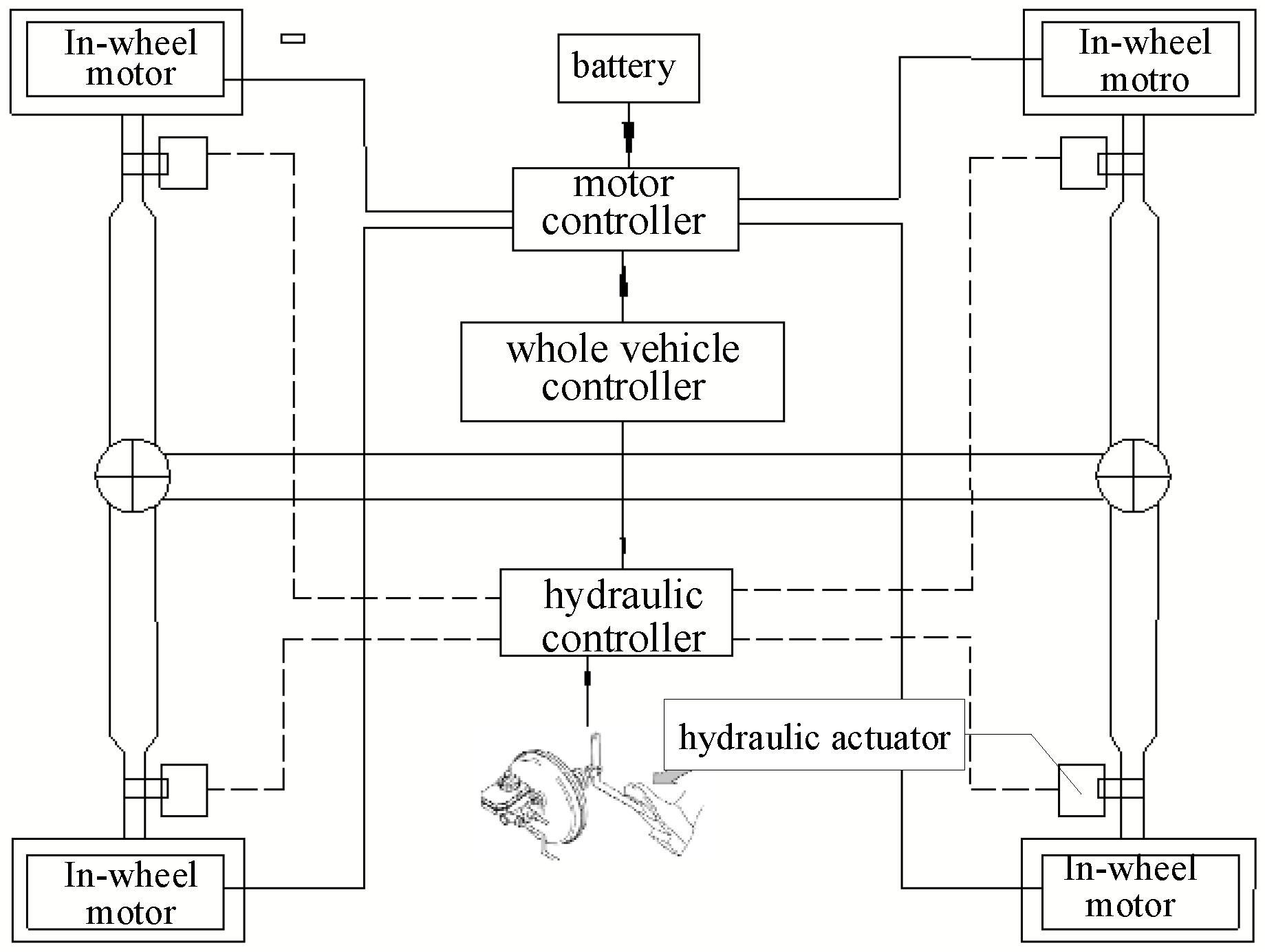
The structure of the electro-hydraulic composite braking system for battery electric vehicles driven by the in-wheel motors is shown in Figure 1. The vehicle speed, road adhesion coefficient, motor speed, battery SOC value, and other vehicle-driving-state variables collected by the vehicle controller are used to determine the braking force distribution ratio of front and rear axles according to the braking force distribution control strategy in this paper, and the motor braking system and hydraulic braking system is controlled to complete the electro-hydraulic braking force distribution ratio of each wheel. The actuator of the braking system executes the braking command to complete the braking requirements of the car. The basic parameters of the vehicle are shown in Table 1.
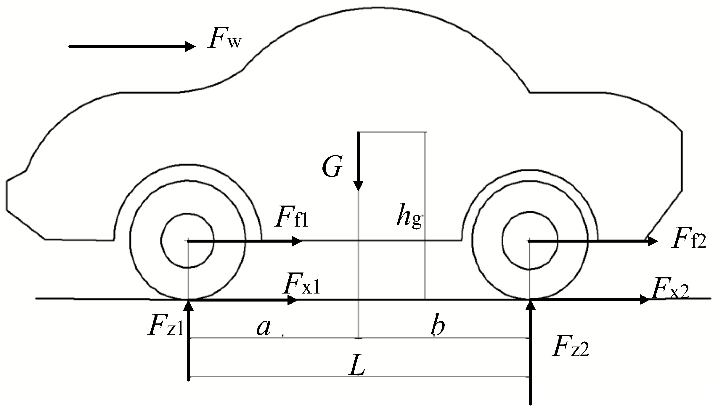
The force for the whole vehicle in the braking process of a battery electric vehicle is shown in Figure 2. By analyzing the force changes of the vehicle in the process of braking, the kinematic equation of the vehicle braking is established as follows:
where M is the mass of the vehicle; a is the braking acceleration of the vehicle; Fx is the ground tangential reaction force; Fw is air resistance; Ff is rolling resistance; µ is pavement adhesion coefficient; CD is the air resistance coefficient; A1 is the effective upwind area of the vehicle; v1 is vehicle speed; and f0 is the rolling resistance coefficient, and the value is 0.012.
2.2. Force Analysis of Single-Wheel Compound Braking
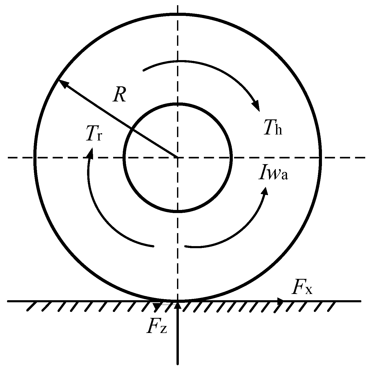
Since the in-wheel motor is independent and controllable, the total braking force output of the wheel is composed of the electric braking force and hydraulic braking force. The force of the wheel is shown in Figure 3, and the motion equation of single-wheel electro-hydraulic composite braking is determined as follows:
where I is the moment of the inertia of the wheel; wa is wheel braking angular acceleration; R is wheel radius; Tr is regenerative braking torque; Th is hydraulic mechanical braking torque; m is wheel mass; and Fr and Fh are regenerative braking force and mechanical braking force, respectively.
3. Dynamic Modeling and Dynamic Characteristics of the Braking System
The electro-hydraulic composite braking system is mainly composed of a hydraulic braking subsystem and an electric braking subsystem. The hydraulic braking subsystem is primarily composed of a hydraulic brake controller, EHB hydraulic actuator, and sensor components. The electric braking subsystem primarily consists of an electric brake controller, motor, and sensor components. Because of its unique structure, the vehicle with an electro-hydraulic composite braking system has a variety of braking mode choices, on the one hand, to better deal with the complex and changeable braking situation. On the other hand, it can realize the recovery of braking energy and improve the driving range to ensure braking safety. However, due to the difference in response speed between electric braking and hydraulic braking, torque mutation occurs in the process of braking mode switching due to the difference in response, thus reducing the ride comfort in the braking process. Therefore, by establishing the dynamic response model of the vehicle’s electro-hydraulic composite braking, we can analyze the response process of electric braking and hydraulic braking and explore the key factors affecting the hydraulic response speed. We can also analyze the dynamic response in the process of electric braking and hydraulic braking and formulate corresponding control strategies for different systems.
3.1. Modeling of in-Wheel Motors
The permanent magnet synchronous motor with high power density and reliability is adopted. To give full play to the working characteristics of the motor, and according to the characteristic that the energy consumed by the electric braking is more incredible than the power recovered when the motor speed is lower than the minimum speed [17], the motor model is established as follows:
where T0 is the rated torque of the motor, and ig and i0 are the transmission ratio of the transmission and the main reducer. Since the hub motor directly drives the wheels, both ig and i0 are 1; is the transmission system efficiency, which is taken as 100%; R is wheel radius; P1 is the load power of the motor; n is motor speed; n0 is the rated speed of the motor; and nmin is the minimum motor speed.
The electric braking torque can be controlled by controlling the motor load power when the motor speed is lower than the rated speed, and the motor load power is calculated as follows:
where P0 is the rated power of the motor, Preg is motor power generation, w is the angular speed of wheel rotation, and is the power generation efficiency of the motor.
3.2. Modeling of the EHB
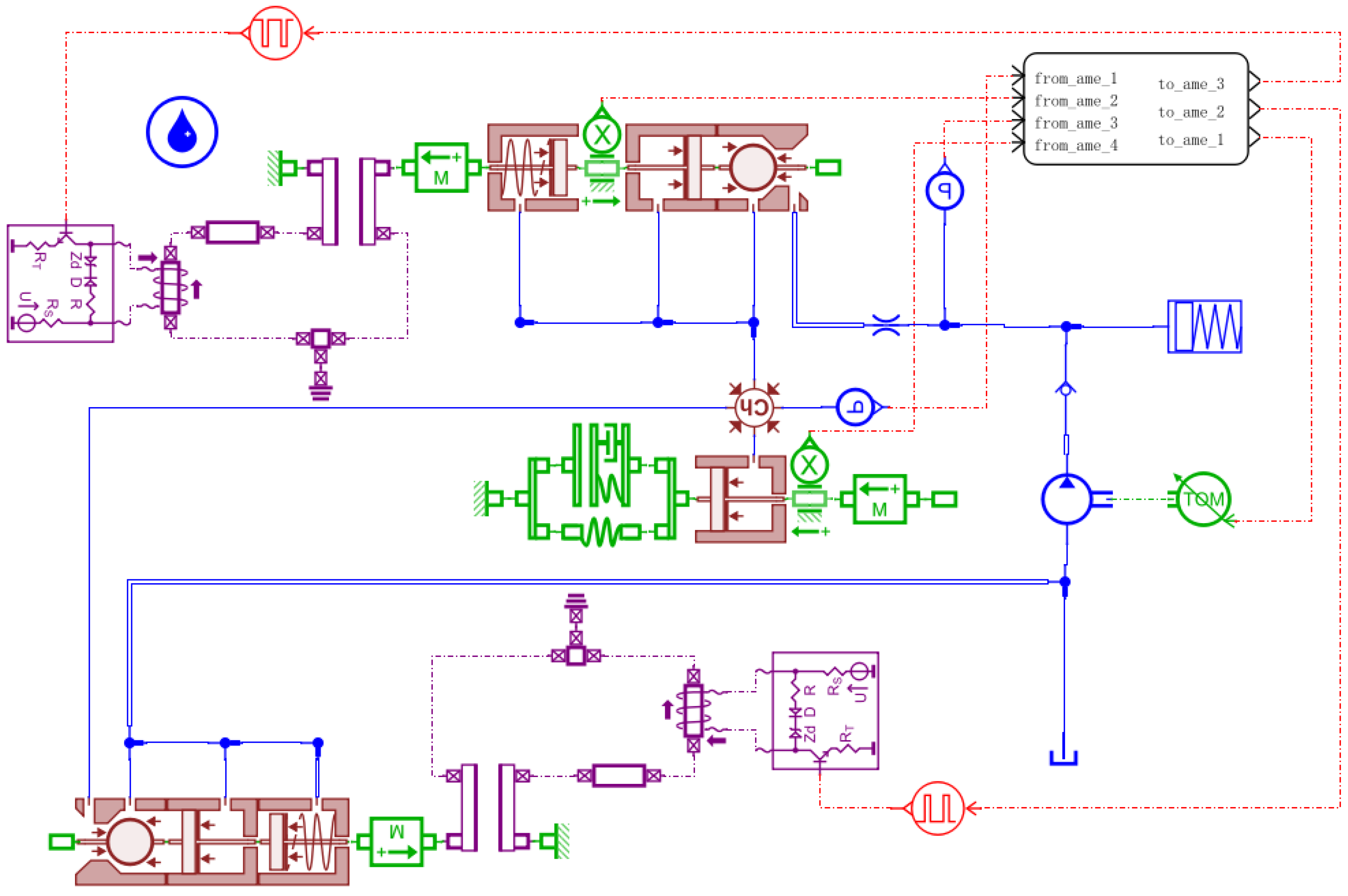
In this study, “high-pressure accumulator + hydraulic pump” type EHB with small volume and good stability was selected, and it is mainly composed of the high-pressure accumulator, motor pump, high-speed switch valve, brake wheel cylinder, and other parts. Combined with the EHB workflow, the single-wheel EHB system model is built by AMESim, its motion response is analyzed, and the motion equation of each component is deduced. This is shown in Figure 4.
The EHB accumulator mainly uses the skin-type high-pressure accumulator, according to Boyle’s law. Its model can be expressed as follows:
where P2, Pmax, Pmin, and P are the initial charging pressure, maximum working pressure, minimum working pressure, and current working pressure of the accumulator, respectively; V0, V1, V2, and V correspond, respectively, to the volume of the gas under pressure.
When the internal pressure of the high-voltage accumulator drops to the lower limit threshold, the motor pump starts to work to raise the high-pressure accumulator pressure to the upper limit threshold, and its mathematical model can be expressed as follows:
where Qout is the output flow of the motor pump, Vc is oil pump displacement, S is the motor speed, E is the cumulative modulus of brake fluid, pin is the pressure at the inlet end of the oil pump, pout is the outlet pressure of oil pump, and a is the pressure factor of the oil pump
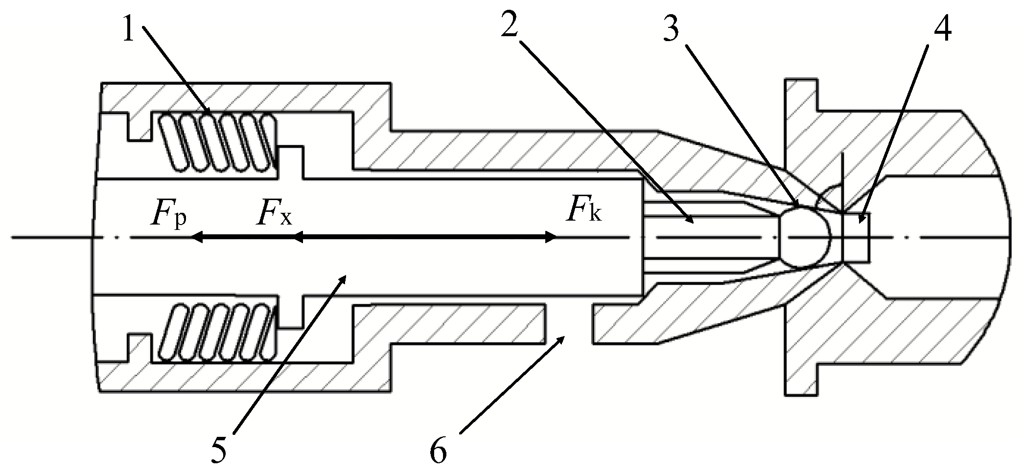
EHB brake response process is mainly composed of the high-speed on/off valve response process and brake wheel cylinder pressure to brake force conversion process. Combined with the dynamic response process of the high-speed on–off valve, analyzed the dynamic force model of the high-speed on–off valve, then explored the key factors affecting the response speed of the high-speed on–off valve. The force diagram of the high-speed on–off valve structure is shown in Figure 5.
Based on the kinematic force model of the high-speed on–off valve in Figure 4, the dynamic response motion equation of the high-speed on–off valve is derived as follows:
where Fm (x, i) is the electromagnetic force of the solenoid valve; Fp is the liquid pressure at the valve port; Fk is spring force; m is the mass of the spool; x1 is the displacement of the spool; v2 is the moving speed of the spool; ΔP is the pressure difference on both sides of the inlet and outlet valve; S1 is the working area of the ball valve at the inlet valve port; x0 is the initial preload displacement of the solenoid valve; K1 is the spring strength coefficient of the solenoid valve spring; N is the number of solenoid valve coil turns; l0 is the initial air gap size; µ0 is the vacuum permeability, and the value is 4 × 10⁻⁷; A2 is the effective area of the armature; and i is the current of the solenoid valve.
The differential equation for the high-speed on–off valve control circuit is calculated as follows [18]:
where U is the driving voltage of the on–off valve control circuit, R is the equivalent internal resistance of the control circuit, and L(x) is the inductance of the on–off valve coil and is a displacement function. The calculation formula of coil inductance is calculated as follows:
where D is the diameter of the valve core, lv is the armature length of the part of the valve core, and r is the average length of the non-working clearance.
The flow characteristics of the on–off valve are affected by many factors, such as the shape of the valve port, the pressure difference between the inlet and outlet, the cross-sectional flow area of the valve port, and the viscosity and density of the brake fluid to facilitate control and verify its main influencing factors. The flow model of the on–off valve port is simplified as follows [19,20]:
where Q is the valve port flow of the on–off valve, Cq is the maximum flow coefficient of the on–off valve, A3 is the flow area of the valve port, and ρ is the hydraulic oil density.
Because the flow rate of the valve port is related to the shape of the valve port, to reduce the fluid resistance during the flow of brake fluid, the ball valve port with basically no flow resistance when it is fully opened is selected. According to the valve port structure in Figure 5, the formula for calculating the cross-sectional flow area of the valve port is expressed as follows:
where θ is the ball seat angle, with values of 60°.
Combine the transformation process of the wheel cylinder pressure to braking force and select the caliper disc brake, for which the braking process can be simplified into an equivalent spring-damping model, to solve the model to explore the key factors affecting the transformation speed. The motion equation of the brake wheel cylinder is expressed as follows:
where m2 is the piston mass of the wheel cylinder, x2 is the piston stroke, P2 is the pressure of the brake wheel cylinder, S2 is the action area of a piston, and K2 is the equivalent elastic coefficient.
The relationship between the hydraulic braking force of the front and rear shafts and the wheel cylinder pressure is calculated as follows:
where FF and FR are the hydraulic braking forces of front and rear shafts; DF and DR are the front and rear axle brake disc effective radius; µF and µR are the front and rear axle brake factor; n is the number of friction surfaces of the brake disc; and PR and PF are the pressure of front and rear axle brake wheel cylinders.
3.3. Difference Analysis of the Dynamic Response of Electro-Hydraulic Braking
The hydraulic brake system models involve the high-speed on–off valve, brake wheel cylinder, and high-pressure accumulator, which AMESim established. Simulink is used to establish the model of the electric braking system to analyze the response difference between electric braking and hydraulic braking. The critical parameters of electric braking are shown in Table 2, and the main parameters of the hydraulic braking model are shown in Table 3, Table 4, Table 5 and Table 6.
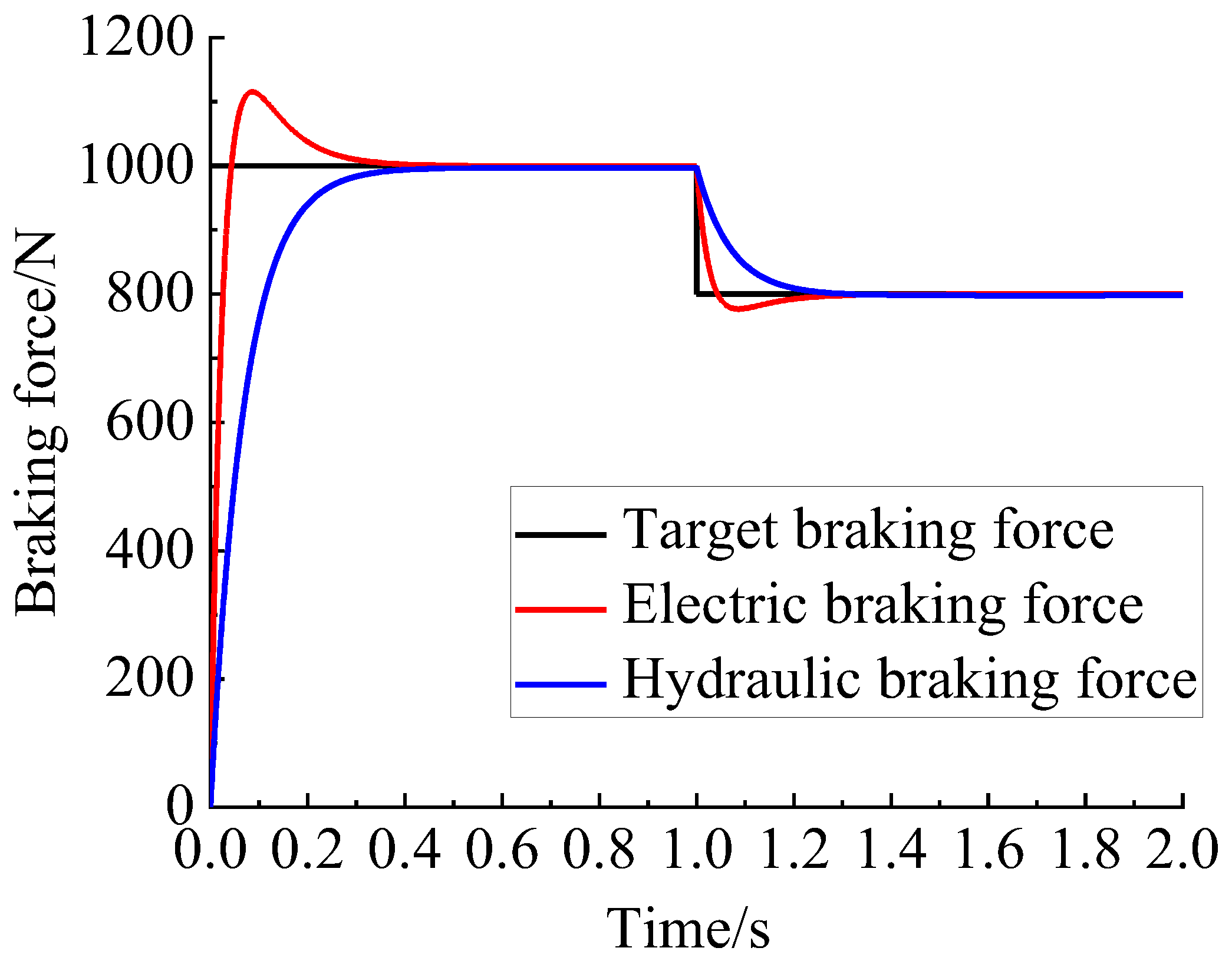
Hydraulic braking and electric braking take the same target torque, and the braking response is obtained by solving the electric brake and hydraulic brake models shown in Figure 6.
It can be seen from Figure 6 that the electric braking response speed is significantly faster than hydraulic braking. The electric braking had an overshoot in the response process without control which quickly caused the fluctuation of braking torque. The slow response of hydraulic braking will lead to insufficient braking in the vehicle braking process and reduce the braking efficiency.
In conclusion, the hysteresis of hydraulic braking response and the overshoot of electric braking response will cause a sudden change of braking torque in braking mode switching. Therefore, analyzing the key factors influencing the hysteresis of hydraulic braking response, designing the fuzzy controller to improve hydraulic brake response speed, and designing a feedforward–feedback PID controller to reduce the difference of electro-hydraulic composite braking response by controlling the electric braking system are necessary.
4. Analysis of Influencing Factors of EHB Response Speed
The opening speed of the high-speed on–off valve and the brake wheel cylinder pressure-building speed determine the EHB response speed. The structural parameters directly influence the opening response speed of the high-speed on–off valve and the pressure-building speed of the brake wheel cylinder. Therefore, it is necessary to analyze the influence law of different structural parameters on the response speed of the high-speed on–off valve and brake wheel cylinder before formulating the dynamic coordinated control strategy of electro-hydraulic composite braking torque. Therefore, the EHB dynamic response model is built on the AMESim and MATLAB/Simulink co-simulation platforms. By solving the model, the influences of different structural parameters on the response speed of the high-speed on–off valve and the response speed of the brake wheel cylinder are obtained. Then the optimal structural parameters are determined.
4.1. Analysis of Influencing Factors of High-Speed On–Off Valve Response Speed
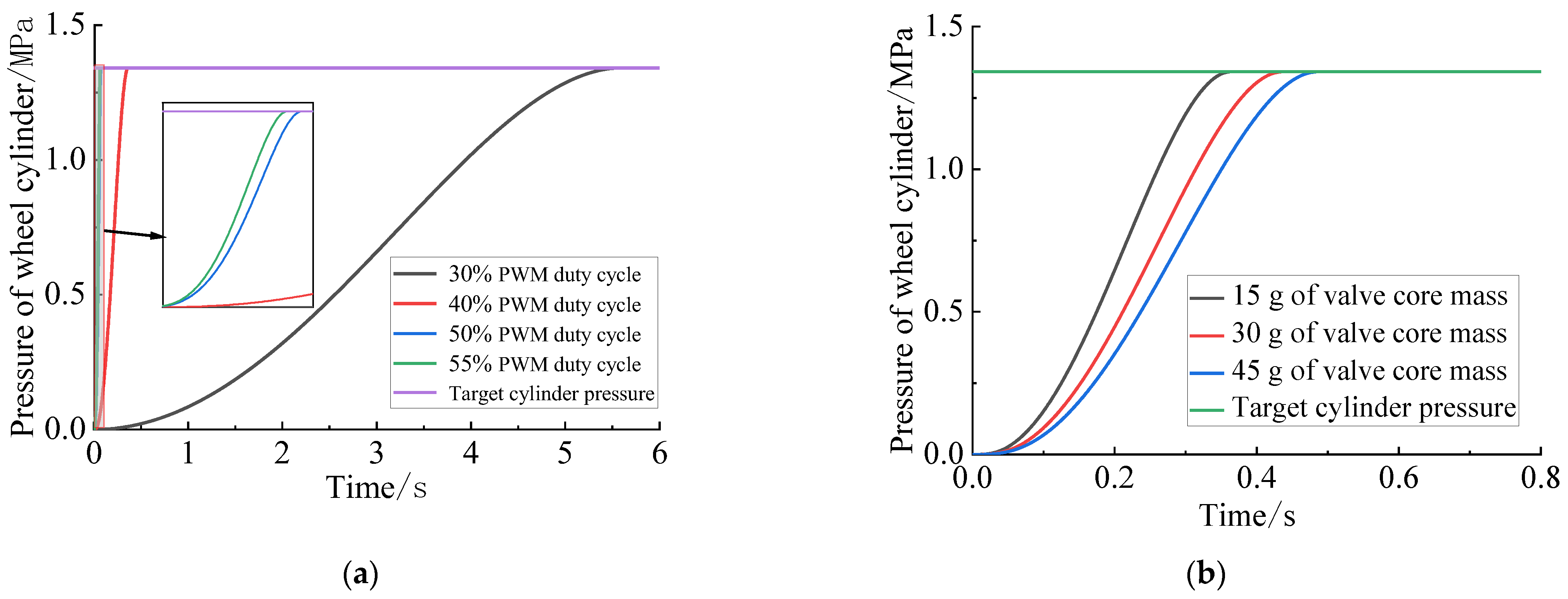
The controllable PWM voltage signal is used as the control signal and the target braking pressure is set as 1.2 MPa. To select the PWM duty cycle of 30%, 40%, 50%, and 55% and the valve core mass of 15 g, 30 g, and 45 g. The response of the high-speed on–off valve response model is simulated and solved which response is shown in Figure 7.
It can be seen in Figure 7 that the larger the PWM duty cycle, the smaller the spool mass, and the faster the high-speed on–off valve response speed. When the duty cycle is greater than 50%, the response speed of the high-speed on–off valve does not improve significantly, the movement condition of the valve core piston gradually worsens, and the service life becomes shorter. At the same time, in practical application, the quality of the valve core is certain when the size of the on–off valve is determined. Therefore, the quality of the spool can be changed by changing the spool material. It is essential to select the appropriate duty cycle when meeting the requirements of braking response.
4.2. Analysis of Influencing Factors of Brake Wheel Cylinder Response Speed
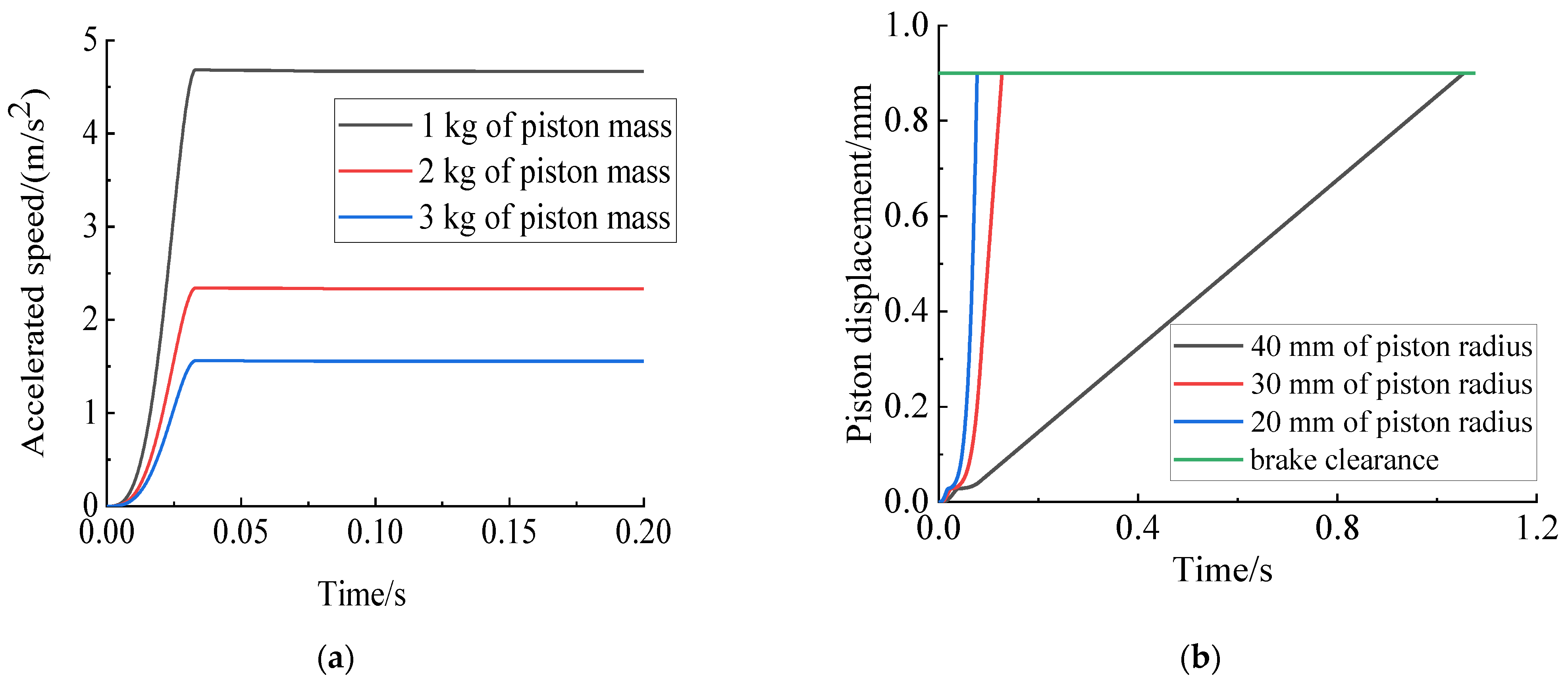
Set the brake clearance to be eliminated for the brake wheel cylinder as 0.9 mm, and then select the piston mass as 1 kg, 2 kg, and 3 kg and choose the radius of the piston action area as 20 mm, 30 mm, and 40 mm through the simulation and solution for the equivalent model of the brake wheel cylinder. The brake wheel cylinder is shown in Figure 8.
It can be seen in Figure 8 that the smaller the piston mass and piston radius in the brake wheel cylinder, the greater the piston motion acceleration and the acceleration change rate. The lower the brake clearance elimination time under the same pressure, the faster the hydraulic brake response speed. At the same time, the structural parameters of the brake wheel cylinder can be changed through the finite element force analysis of the piston to change the structure or change the piston material to reduce the mass of the piston.
In conclusion, the optimal PWM duty ratio and high-speed on–off valve and brake wheel cylinder parameters can significantly improve the response speed of the EHB braking system. Combined with the relationship between the maximum pressure of the brake wheel cylinder and structural parameters [21] and the simulation results, the selected piston mass of the on–off valve is 20 g, the piston mass of the brake wheel cylinder is set as 1 kg, and the radius of piston action area is 20 mm, giving the EHB a faster response speed and better linear adjustment ability. Furthermore, it provides a theoretical basis for developing the dynamic coordinated control strategy of electro-hydraulic composite braking torque for an electric vehicle driven by an in-wheel motor under optimal structural parameters.
5. Dynamic Coordination Control Strategy of Electro-Hydraulic Composite Braking Torque
The vehicle is faced with the switch of various braking modes in the braking process because of the complex and variable road adhesion in the actual driving process, thus leading to the sudden change of braking torque and the consequent reduction of car-ride comfort. Therefore, a strategy is proposed to control the braking torque fluctuation in braking mode switching to improve vehicle ride comfort.
5.1. Distribution of Front and Rear Axle Braking Torque
The front and rear brake force distribution is obtained by the ideal braking force distribution method to make full use of the ground adhesion coefficient and improve the braking effect. The front and rear braking force expression is as follows:
where Fµ1 is front axle braking force, Fµ2 is rear axle braking force, hg is the height of the center of mass, L is the distance between the front and rear axis, and b is the distance between the center of mass and the posterior axis.
Because the choice of braking mode is influenced by ECE regulations, battery SOC value, motor speed, and other factors, the actual braking process of the automobile is faced with the switching of the single motor braking mode, single hydraulic braking mode, and electric–hydraulic composite braking mode [22]. The braking mode switching logic is shown in Figure 9.
The following principles are formulated in the electro-hydraulic hybrid braking mode to determine the torque distribution relationship between electric braking and hydraulic braking: (1) Electric braking is the main braking mode, and hydraulic braking is used to compensate when electric braking is insufficient. (2) When the electric braking is insufficient, the fluctuation range of braking force under steady-state hydraulic braking is calculated, and the corresponding electric braking moment is reserved to compensate for the braking force when the hydraulic braking reaches steady state.
5.2. Design of Electro-Hydraulic Composite Brake Controller
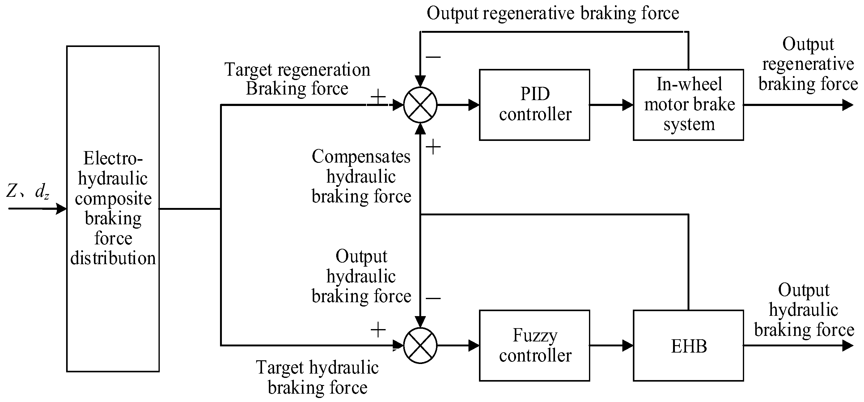
Considering that the hydraulic brake should have an excellent pressure-following ability, the fuzzy controller is designed to control the high-speed on/off valve so that the actual brake wheel cylinder pressure can quickly and accurately follow the ideal target pressure. At the same time, due to the fact that electric braking has the characteristics of fast response speed and good controllability, the PID controller with feedforward–feedback is designed to make the electric braking meet the ideal braking force requirements quickly and compensate for the defects of insufficient hydraulic response in order to ensure that the output total braking force meets the braking requirements. The controller control logic is shown in Figure 10.
5.2.1. Design of Fuzzy Controller for Hydraulic Braking
As a common control algorithm, fuzzy control is widely used in automotive research because of its excellent performance in nonlinear system control. However, the selection of control parameters, the determination of parameter variation range, and the formulation of fuzzy rules determine whether the control algorithm has good control ability [23,24,25].
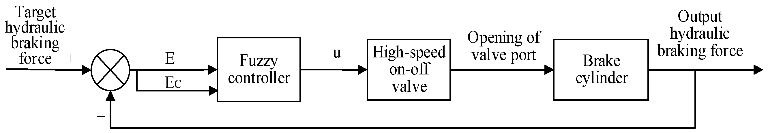
The input of the fuzzy controller is the deviation, E, and the deviation change rate, EC, between the output pressure of the brake wheel cylinder and the target pressure of the brake wheel cylinder, and the output, u, is the duty cycle of PWM. The specific control logic is shown in Figure 11.
According to the parameters of the hydraulic braking system, the deviation range (E) between the output pressure of the brake wheel cylinder and the target pressure of the brake wheel cylinder is −4~4 MPa, and the deviation rate (EC) is −300~300 MPa/s. Formula (8) was used to determine the PWM duty cycle minimum extent, which was 22%. The influence rule of the PWM duty ratio on the response speed of the on–off valve in Section 3 determines the maximum regulation limit of PWM to be 50%, so the regulation range of the PWM duty ratio is 22–50%.
Different quantization factors are selected to make the fuzzy domain range the same to achieve the purpose of simplifying control. The input and output fuzzification of the inlet and outlet valves are shown in Table 7.
5.2.2. Design of Feedforward and Feedback PID Electric Brake Controller
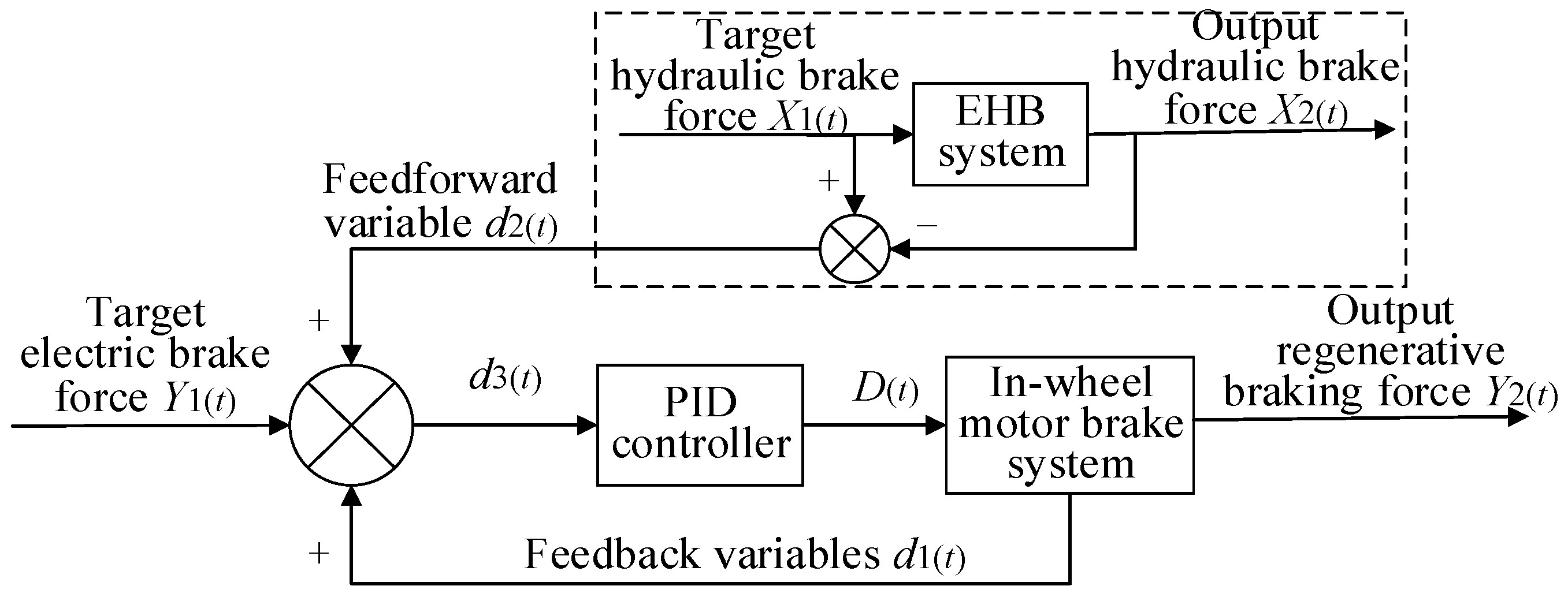
Although choosing appropriate model parameters and designing the fuzzy controller can improve the hydraulic brake’s response speed, the response speed is still lower than the electric braking. Therefore, the difference between the target hydraulic braking force and the actual hydraulic braking force is regarded as the feedforward variable of electric braking. The error generated in the process of electric braking is taken as the feedback variable. Then a feedforward and feedback PID controller are designed to control the electric braking response process to ensure the total braking torque output of the wheel meets the braking requirements. The logic control principle is shown in Figure 12.
The target braking force and output braking force state variables of hydraulic braking are defined as X1(t) and X2(t), respectively, and the target braking force and output braking force state variables of electric braking are Y1(t) and Y2(t):
where D1(t), D2(t), and D3(t) are feedback variables, feedforward variables, and total error regulation variables, respectively.
The mathematical model of the PID controller is calculated as follows:
where D(t) is the electric braking control coefficient; and kp and ki are the proportion and integral coefficient, respectively.
6. Simulation Verification
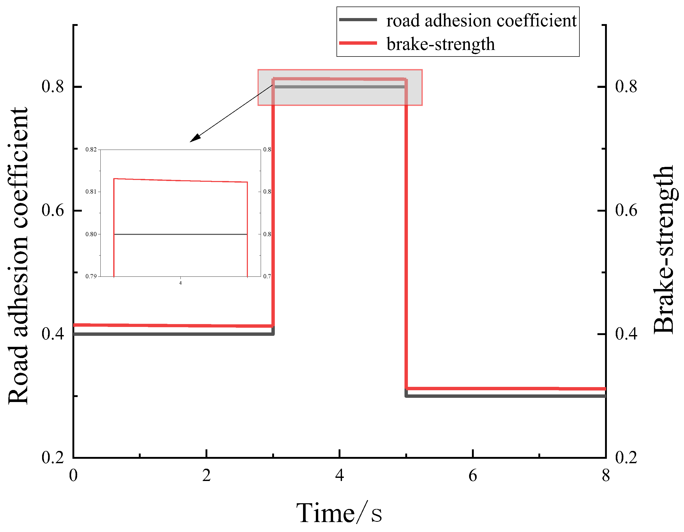
To verify the effectiveness of the strategy in the braking mode switching process, the Simulink–Carsim–AEMsim co-simulation platform was built. Given the frequent switching between general braking and emergency braking, and general braking and slow braking in the electro-hydraulic composite braking process, the initial braking speed of the vehicle was set as 150 km/h. Then the variable ground adhesion coefficient is standard in actual vehicle operation that is selected as the input. The cycle braking working condition for the design of specific braking mode switching is shown in Figure 13.
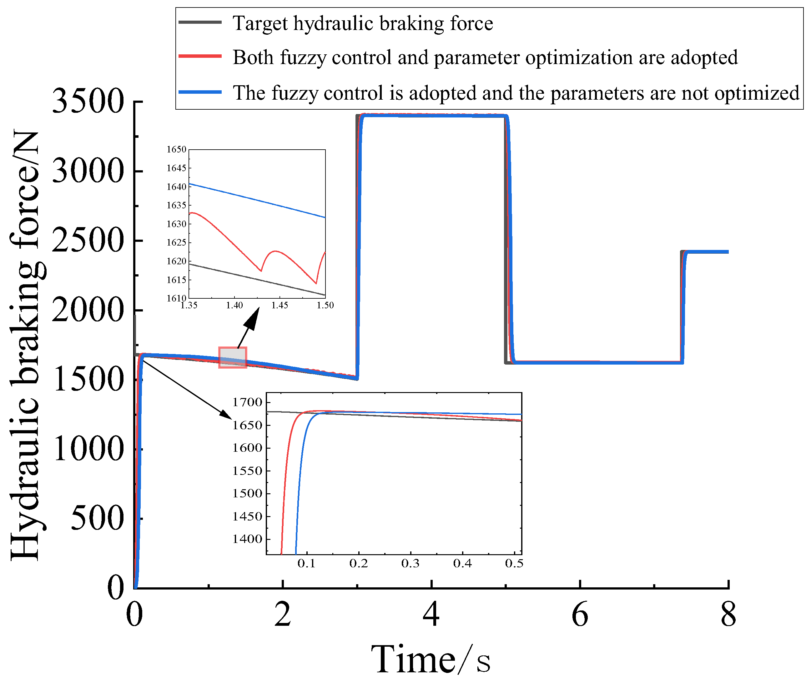
Under the same fuzzy control regulation, the hydraulic braking system without parameter optimization and the hydraulic braking system after parameter optimization were compared and analyzed. Details of structural parameters are shown in Table 9, and simulation results are shown in Figure 14.
It can be seen from the figure that the response speed of the hydraulic braking system after parameter optimization is increased by 25.4%, and the steady-state pressure fluctuation range under fuzzy control is about 0–82 N. At the same time, it is verified that the fuzzy controller designed in this paper can ensure that the brake wheel cylinder pressure always follows near the target pressure with or without parameter optimization and that the steady-state error does not exceed 2.3%.
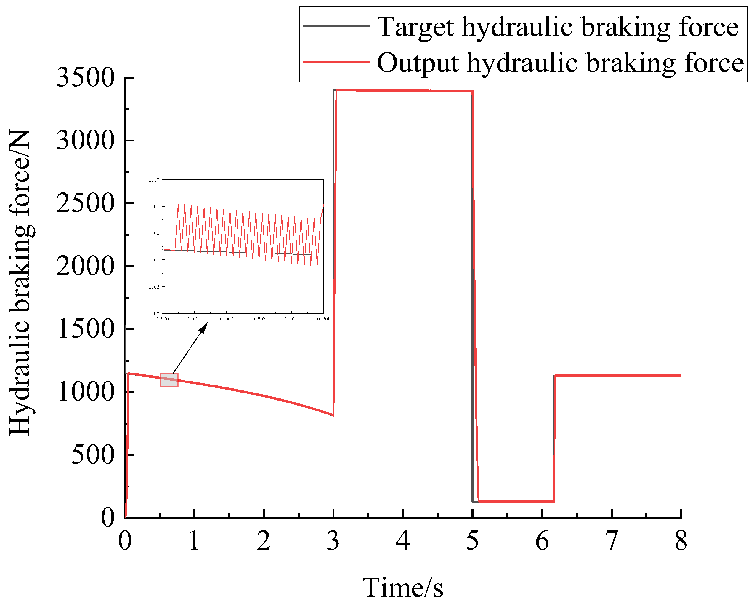
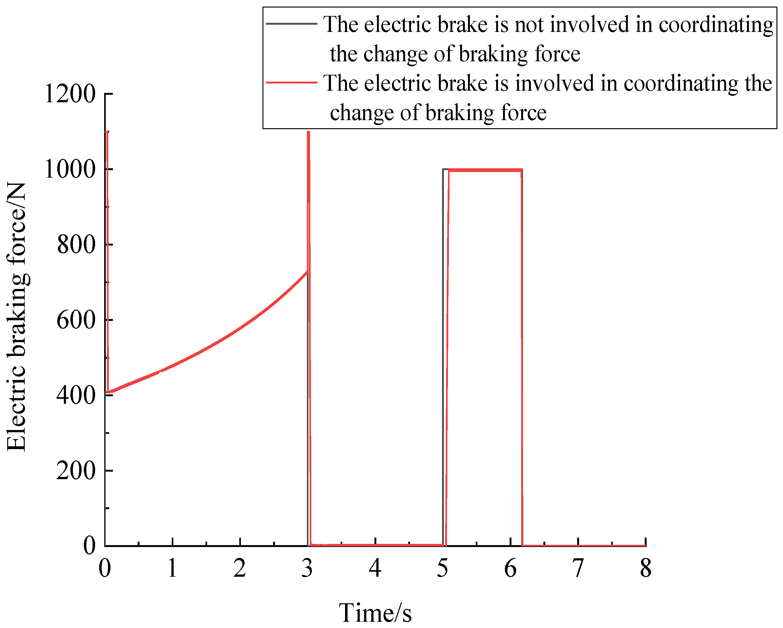
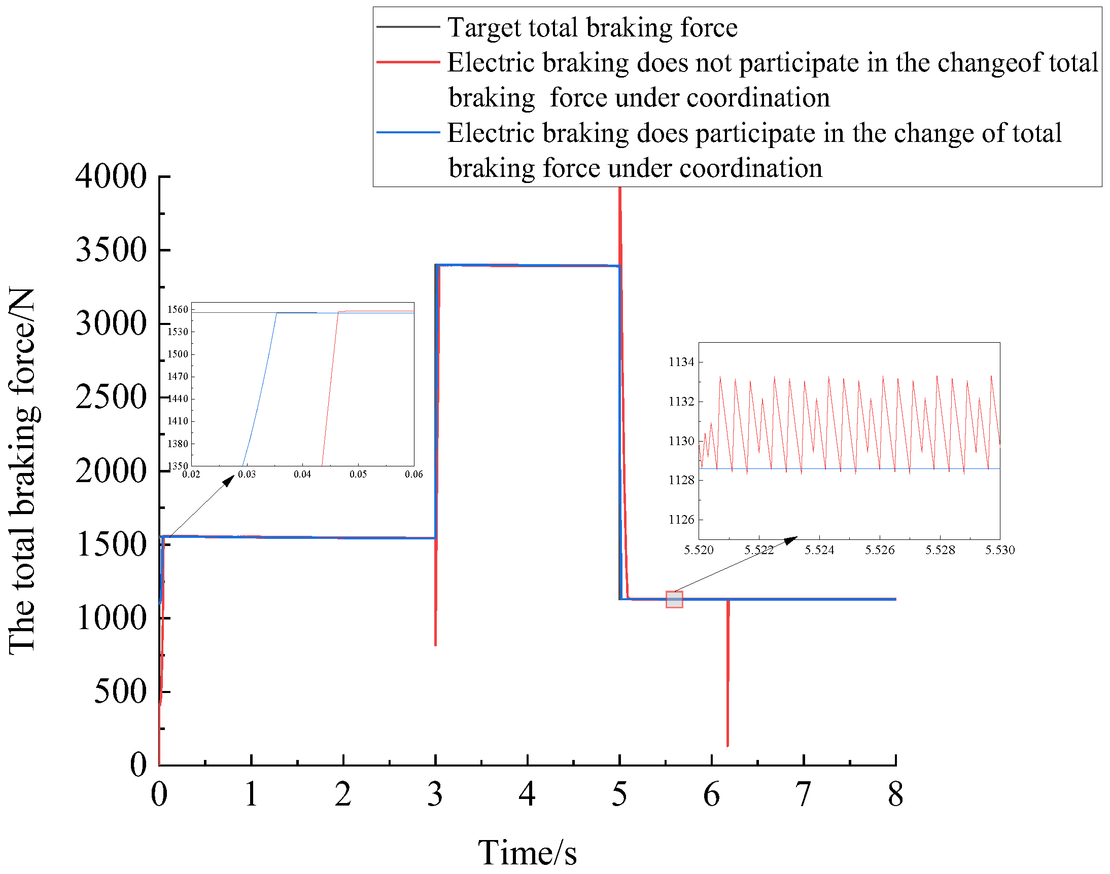
Based on improving the hydraulic response speed, the uncoordinated motor compensation control strategy was compared and analyzed with the dynamic coordinated control strategy of electro-hydraulic composite braking torque proposed in this paper. The single wheel output electric braking force, the single wheel output hydraulic braking force, the total braking force output of the single wheel, and the change of the impact degree before and after the coordination of the whole vehicle are shown in Figure 15, Figure 16, Figure 17 and Figure 18, respectively.
It can be seen from the figure that when the braking mode switch occurs in the process of automobile braking, the control strategy proposed in this paper can effectively reduce the fluctuation of braking torque and the resulting impact caused by the braking mode switch. The maximum impact degree is no more than 6.25, and the ride comfort of automobile braking is significantly improved.
7. Conclusions
According to the dynamic response model of the electronic hydraulic brake system, it is necessary to analyze the key factors influencing the EHB response speed and its influence on the EHB rule and then optimize the EHB model parameters to improve hydraulic brake response speed by 25.4%, which proves that the change of structural parameters can improve the response speed of hydraulic braking. According to the sudden change of torque in the switching process of the electro-hydraulic composite braking mode, a dynamic coordinated control strategy of braking torque under mode switching is proposed. The results show that the steady-state error of output pressure of the brake wheel cylinder is less than 2.3%, and the impact degree is less than 6.25.
With the further research of electro-hydraulic composite braking systems, the hydraulic braking prediction module can be added in the future. By designing the driver’s braking intention recognition controller, the hydraulic braking system is controlled in advance to eliminate the internal brake clearance when the braking starts, and then it improves the hydraulic brake response speed. At the same time, the influence of wheel inertia increase caused by the location of the in-wheel motor on the vehicle brake stability is considered, which makes the consideration factor of the braking process more perfect and fit better with the actual running state of automobile braking. In the future, the ride comfort, braking efficiency, and maximum braking energy recovery in the braking process can be taken as optimization objects. A new control strategy of electric and hydraulic braking force distribution can be proposed by using a multi-objective optimization algorithm to enrich the research of electric vehicles driven by in-wheel motors in the field of braking and better meet the actual manufacturing requirements.
Author Contributions
Conceptualization and supervision, Z.Z.; conception and design, Z.Z.; manuscript writing, X.Y.; image description, J.Z. All authors have read and agreed to the published version of the manuscript.
Funding
This work is supported by the National Natural Science Foundation of China (51805149), the Major Project of Henan Province in 2022 (221100240400), and the major project of Ningbo Science and Technology Innovation 2025 “Development of Light Electric Vehicle Hub Motor and Control System” (2019B10073).
Institutional Review Board Statement
Not applicable.
Informed Consent Statement
Not applicable.
Data Availability Statement
Not applicable.
Conflicts of Interest
The authors declare no conflict of interest.
References
- Qingsong, T.; Yang, Y.; Chang, L.; Zhong, Y.; Chunyun, F. A novel electro-hydraulic compound braking system coordinated control strategy for a four-wheel-drive pure electric vehicle driven by dual motors. Energy 2022, 241, 122750. [Google Scholar]
- Gnuey, B.; Kilic, H. A Review on the Research Progress of Regenerative Brake System. J. Res. Sci. Eng. 2021, 3, 116–160. [Google Scholar]
- Fengjiao, Z.; Minxiang, W. Multi-objective optimization of the control strategy of electric vehicle electro-hydraulic composite braking system with genetic algorithm. Adv. Mech. Eng. 2015, 7, 1687814014568491. [Google Scholar] [CrossRef]
- Xu, W.; Chen, H.; Zhao, H.; Ren, B. Torque optimization control for electric vehicles with four in-wheel motors equipped with regenerative braking system. Mechatronics 2019, 57, 95–108. [Google Scholar] [CrossRef]
- Hu, D.-H.; He, R. Regenerative Braking Control Strategy of an Electro-Hydraulic Hybrid Brake System. J. Highw. Transp. Res. Dev. 2015, 9, 105–110. [Google Scholar] [CrossRef]
- Zheng, P.; Xiao, Y.; Hui, J.; Boyuan, L.; Rongrong, W. Electro-hydraulic Composite Emergency Braking System Based on Frequency Reconstruction Control. J. Phys. Conf. Ser. 2021, 1820, 012146. [Google Scholar]
- Pan, H.; Guo, X.; Pei, X.; Sun, D. Pressure controlling of integrated electro-hydraulic braking system with considering driver brake behaviour. Int. J. Veh. Des. 2019, 79, 248–272. [Google Scholar] [CrossRef]
- Aksjonov, A.; Ricciardi, V.; Augsburg, K.; Vodovozov, V.; Petlenkov, E. Hardware-in-the-loop test of an open-loop fuzzy control method for decoupled electrohydraulic antilock braking system. IEEE Trans. Fuzzy Syst. 2020, 29, 965–975. [Google Scholar] [CrossRef]
- Yu, Z.; Shi, B.; Xiong, L.; Han, W. Coordinated Control under Transitional Conditions in Hybrid Braking of Electric Vehicle. In Proceedings of the SAE 36th Annual Brake Colloquium and Exhibition, Palm Desert, CA, USA, 14–17 October 2018; p. 1869. [Google Scholar]
- Yang, Y.; He, Y.; Yang, Z.; Fu, C.; Cong, Z. Torque Coordination Control of an Electro-Hydraulic Composite Brake System During Mode Switching Based on Braking Intention. Energies 2020, 13, 2031. [Google Scholar] [CrossRef] [Green Version]
- Wang, C.; Zhao, W.; Li, W. Braking sense consistency strategy of electro-hydraulic composite braking system. Mech. Syst. Signal Process. 2018, 109, 169–219. [Google Scholar] [CrossRef]
- Zhongshi, Z.; Ruihai, M.; Lifang, W.; Junzhi, Z. Novel PMSM Control for Anti-Lock Braking Considering Transmission Properties of the Electric Vehicle. IEEE Trans. Veh. Technol. 2018, 67, 10378–10386. [Google Scholar]
- Kumar, C.S.N.; Subramanian, S.C. Cooperative control of regenerative braking and friction braking for a hybrid electric vehicle. Proc. Inst. Mech. Eng. Part D J. Automob. Eng. 2016, 230, 103–116. [Google Scholar] [CrossRef]
- Feng, Z.; Hao, L.; Liang, T.G.; Wei, Z. Design, Modeling and Simulation of an Innovation Pneumatic High Speed on-Off Valve Based on Giant Magnetostrictive Material. Adv. Mater. Res. 2011, 422, 243–249. [Google Scholar]
- Wagh, M.N.; Alamelu Manghai, T.M.; Jegadeeshwaran, R.; Saravanakumar, D.; Raghukiran, N. Application of Meta family Classifiers for monitoring hydraulic brake system using vibration based statistical learning approach. J. Phys. Conf. Ser. 2021, 1969, 012050. [Google Scholar] [CrossRef]
- He, W.; Zhen, C.; Jiahai, H.; Long, Q.; Bin, Z. Development of High-Speed On–Off Valves and Their Applications. Chin. J. Mech. Eng. 2022, 35, 67. [Google Scholar]
- Nadeau, J.; Micheau, P.; Boisvert, M. Collaborative control of a dual electro-hydraulic regenerative brake system for a rear-wheel-drive electric vehicle. Proc. Inst. Mech. Eng. Part D J. Automob. Eng. 2019, 233, 1035–1046. [Google Scholar] [CrossRef]
- Wang, S.; Zhang, B.; Zhong, Q.; Yang, H. Study on pilot high-speed switching valve control performance. Adv. Mech. Eng. 2017, 9, 1687814017708908. [Google Scholar] [CrossRef] [Green Version]
- Qin, Y.J.; Wu, Z.Y.; Mo, Z.Y.; Wang, X.; Wang, J. The simulation analysis of the high speed switch valve control the cartridge valve based on AMEsim. Adv. Mater. Res. 2014, 971, 827–832. [Google Scholar] [CrossRef]
- Gao, Q.; Zhu, Y.; Luo, Z.; Bruno, N. Investigation on adaptive pulse width modulation control for high speed on/off valve. J. Mech. Sci. Technol. 2020, 34, 1711–1722. [Google Scholar] [CrossRef]
- Anselma, P.G.; Patil, S.P.; Belingardi, G. Rapid optimal design of a light vehicle hydraulic brake system. SAE Tech. Pap. 2019, 31, 148–7191. [Google Scholar]
- Hu, D. Mode Switching Control of Hybrid Brake-By-Wire System. In Design and Control of Hybrid Brake-by-Wire System for Autonomous Vehicle; Springer: New York, NY, USA, 2022; pp. 105–149. [Google Scholar]
- Girovský, P.; Žilková, J.; Kaňuch, J. Optimization of Vehicle Braking Distance Using a Fuzzy Controller. Energies 2020, 13, 3022. [Google Scholar] [CrossRef]
- Wang, X.G.; Li, L.; Han, H.L.; Wei, X.L.; An, M.D.; Liu, B.F. Electro-hydraulic servo actuator parameters self-tuning three-dimensional fuzzy control research. Appl. Mech. Mater. 2014, 607, 811–814. [Google Scholar] [CrossRef]
- Zhai, X.H.; Yao, S.X.; Xu, Z.H. Research on Fuzzy Control of Inverted Pendulum in the MATLAB Environment. Appl. Mech. Mater. 2012, 182, 1211–1214. [Google Scholar] [CrossRef]
- Zhang, L.; Liu, Q.; Wang, Z. Electro-hydraulic Brake Control for Improved Ride Comfort in Four-wheel-independently-actuated Electric Vehicles. J. Mech. Eng. 2020, 56, 125–134. [Google Scholar]
Figure 1.
Schematic diagram of the brake system structure of the electric vehicle.

Figure 2.
The braking force diagram of the whole vehicle.

Figure 3.
Dynamic model of wheel electro-hydraulic composite braking.

Figure 4.
Schematic diagrams single-wheel EHB system.

Figure 5.
Force structure diagram of the high-speed on–off valve: 1—the spring; 2—valve core; 3—valve head; 4—Liquid inlet; 5—moving iron; 6—fluid outlet.
Figure 5.
Force structure diagram of the high-speed on–off valve: 1—the spring; 2—valve core; 3—valve head; 4—Liquid inlet; 5—moving iron; 6—fluid outlet.

Figure 6.
Response of electric brake and hydraulic brake.

Figure 7.
Response diagram of the high-speed on–off valve. (a) Different PWM duty cycle situations. (b) The condition of different spool quality.
Figure 7.
Response diagram of the high-speed on–off valve. (a) Different PWM duty cycle situations. (b) The condition of different spool quality.

Figure 8.
Response of brake wheel cylinder. (a) The case of different piston qualities. (b) In the case of different piston radius.
Figure 8.
Response of brake wheel cylinder. (a) The case of different piston qualities. (b) In the case of different piston radius.

Figure 9.
Logic diagram of braking mode switching.

Figure 10.
Logic diagram of electro-hydraulic composite brake control.

Figure 11.
Control logic diagram of fuzzy controller.

Figure 12.
Logic diagram of PID control.

Figure 13.
Variation of braking strength under cyclic conditions.

Figure 14.
Response to hydraulic braking.

Figure 15.
Front axle single wheel output electric braking force.

Figure 16.
Front axle single wheel output hydraulic braking force.

Figure 17.
Total braking force output of front axle single wheel.

Figure 18.
Changes of impact degree before and after vehicle coordination.


Table 1.
Basic parameters of the vehicle.
| Parameter | Numerical |
|---|---|
| Mass of the vehicle/kg | 1110 |
| Wheel radius/m | 0.3 |
| Height of the center of mass/m | 0.54 |
| Distance from the center of mass to the front axle/m | 1.04 |
| Distance from the center of mass to the rear axle/m | 1.56 |
| Rolling resistance coefficient | 0.012 |
| Effective upwind area of the vehicle/m2 | 1.6 |
| Air resistance coefficient | 0.3 |
Table 2.
Key parameters of permanent magnet synchronous motor.
| Parameter | Numerical |
|---|---|
| Peak power/kw | 17 |
| Peak speeds/(r/min) | 4000 |
| Rated power/kw | 10 |
| Rated speed/(r/min) | 3000 |
Table 3.
Main parameters of high-pressure accumulator.
| Parameter | Numerical |
|---|---|
| Initial inflation pressure/Mpa | 8 |
| Maximum inflation pressure/Mpa | 10 |
| Minimum inflation pressure/Mpa | 7 |
Table 4.
Motor pump main parameters.
| Parameter | Numerical |
|---|---|
| Oil pump displacement/(cc/rev) | 0.1 |
| Rated motor speed/(r/min) | 3000 |
| Product modulus of brake fluid/bar | 17,000 |
| Oil pump pressure factor | 0.73 |
Table 5.
Main parameters of the high-speed on–off valve.
| Parameter | Numerical |
|---|---|
| Maximum flow coefficient | 0.7 |
| Viscous damping coefficient | 10 |
| Valve port diameter/mm | 6 |
| Reynolds Number | 100 |
| Valve core diameter/mm | 14 |
Table 6.
Main parameters of front and rear axle brakes.
| Parameter | Numerical |
|---|---|
| Effective radius of the brake disc/mm | 120 |
| Braking efficiency factor | 0.8 |
| Number of friction surfaces of the brake disc | 2 |
Table 7.
Input and output fuzzification of inlet and outlet valves.
| Category | Name | The Basic Theory of Domain | Fuzzy Language Set | ||||
|---|---|---|---|---|---|---|---|
| Inlet Valve | E | [−4,0] | ZO | S | MS | M | B |
| EC | [0,300] | B | M | MS | S | ZO | |
| u | [0.22,0.5] | ZO | S | MS | M | B | |
| Outlet Valve | E | [0,4] | ZO | S | MS | M | B |
| EC | [−300,0] | B | M | MS | S | ZO | |
| u | [0.22,0.5] | ZO | S | MS | M | B | |
Table 8.
PWM duty cycle fuzzy rules of inlet and outlet valves.
| u | EC | |||||
|---|---|---|---|---|---|---|
| B | M | MS | S | ZO | ||
| E | ZO | S | S | S | ZO | ZO |
| S | MS | S | S | S | S | |
| MS | M | MS | MS | S | S | |
| M | B | M | M | MS | S | |
| B | B | M | M | MS | MS | |
Table 9.
Key structural parameters of hydraulic braking system.
| The Quality of the Valve Core | The Quality of the Piston | The Radius of the Piston | |
|---|---|---|---|
| Structural parameters are not improved | 30 g | 2 kg | 30 mm |
| Improved structural parameters | 20 g | 1 kg | 20 mm |
Publisher’s Note: MDPI stays neutral with regard to jurisdictional claims in published maps and institutional affiliations. |
© 2022 by the authors. Licensee MDPI, Basel, Switzerland. This article is an open access article distributed under the terms and conditions of the Creative Commons Attribution (CC BY) license (https://creativecommons.org/licenses/by/4.0/).
Share and Cite
MDPI and ACS Style
Zhou, Z.; Yin, X.; Zhang, J. Coordinated Control Strategy of Electro-Hydraulic Composite Braking Torque for the Distributed Electric Vehicles. Machines 2022, 10, 1235. https://doi.org/10.3390/machines10121235
AMA Style
Zhou Z, Yin X, Zhang J. Coordinated Control Strategy of Electro-Hydraulic Composite Braking Torque for the Distributed Electric Vehicles. Machines. 2022; 10(12):1235. https://doi.org/10.3390/machines10121235
Chicago/Turabian StyleZhou, Zhigang, Xiaofei Yin, and Jie Zhang. 2022. "Coordinated Control Strategy of Electro-Hydraulic Composite Braking Torque for the Distributed Electric Vehicles" Machines 10, no. 12: 1235. https://doi.org/10.3390/machines10121235
Note that from the first issue of 2016, this journal uses article numbers instead of page numbers. See further details here.