Article

Internal Flow Characteristics of High-Specific-Speed Centrifugal Pumps with Different Number of Impeller Blades under Large Flow Conditions

1
International Shipping Research Institute, GongQing Institute of Science and Technology, Jiujiang 332020, China
2
College of Hydraulic Science and Engineering, Yangzhou University, Yangzhou 225009, China
3
SHIMGE Pump Co., Ltd., Taizhou 317525, China
4
Institute of Fluid Engineering Equipment, JITRI, Zhenjiang 212013, China
5
National Research Center of Pumps, Jiangsu University, Zhenjiang 212013, China
*
Author to whom correspondence should be addressed.
Machines 2023, 11(2), 138; https://doi.org/10.3390/machines11020138
Submission received: 27 November 2022 / Revised: 11 January 2023 / Accepted: 16 January 2023 / Published: 19 January 2023
(This article belongs to the Special Issue Optimization and Flow Characteristics in Advanced Fluid Machinery)

Abstract

:
As compared with a conventional centrifugal pump, a high-specific-speed centrifugal pump mostly operates under large flow conditions. In this paper, a typical high-specific-speed centrifugal pump is examined, and the effect of the blade number on the internal flow condition is investigated numerically. The numerical predictions have been verified through measurement. It was found that the predictions and the measurements are in good agreement of discrepancy. Serious cavitation could be observed within the pump when the flow rate reached 1300 m3/h. Meanwhile, the effect of the blade number on the cavitation intensity was extremely obvious. The cavitation area at the inlet edge of the blades significantly reduced when the blade number increased from three to six. In addition, the turbulent kinetic energy within the pump was more uniformly distributed. This demonstrates that the blade number can be reasonably chosen to improve the internal flow pattern within the pump, which could provide a theoretical basis for the practical application of high-specific-speed centrifugal pumps

1. Introduction

The performance and operational stability of centrifugal pumps have been a popular research topic in the field of fluid mechanics. Based on the anti-design approach, Hoang et al. [1] adjusted the parameters of the impeller meridian to improve the pump performance. Shen et al. [2] studied the effect of the groove structure on the performance and the flow pattern. This showed that the appropriate arrangement of the groove structure could not only improve the performance of the centrifugal pump at large flow conditions, but could also extend the stable operating range of the centrifugal pump. Based on the above research, the optimization theory of centrifugal pumps has been gradually refined. In the 19th century, the concept of specific speed was first applied to centrifugal pumps and became the most important factor during the design process [3,4,5]. Currently, high-specific-speed centrifugal pumps are widely used in urban buildings for sewage treatment, firefighting, and water supply because of their high conveying flow [6,7,8].
The open literature shows that the combination of theoretical derivations, numerical simulations and experimental studies is performed to optimize the performance of high-specific-speed centrifugal pumps. Hao et al. [9] carried out a theoretical analysis on the current status and deficiencies of existing high-specific-speed centrifugal pumps, which could provide theoretical support for the application of high-specific-speed centrifugal pumps. Ding et al. [10] numerically investigated the effect of blade exit angle on the performance of a high-specific-speed centrifugal pump and found that an appropriate selection of the blade exit angle was important to improve pump performance. Cheng et al. [11] studied the effect of balance orifice area on the performance of high-specific-speed centrifugal pumps. It was found that the area of the balancing bore could change the axial force of the rotor. Huan et al. [12] experimentally investigated the evolution of cavitation within a high-specific-speed centrifugal pump, which provided the basis for improving the cavitation resistance of centrifugal pumps. Since cavitation is an unavoidable problem for centrifugal pumps under high flow conditions, many scholars have also conducted research on the thermal effects of cavitation. Ge et al. [13] analyzed the three unstable states of sheet cavitation, periodic single cloud cavitation and non-periodic multi-cloud cavitation through cavitation flow experiments. They found that the effect of hydrodynamic cavitation was reduced when the water temperature was in the range of 55–60 °C. Rajavamsi et al. [14] elaborated the cavitation phenomenon in the centrifugal pump in detail, predicted the existence of cavitation phenomenon using the acoustic spectrum, and provided an effective method to reduce the noise in the pump. Hu et al. [15] studied the flow characteristics within the pre-swirl system of a marine gas turbine at low rotational speed by varying the pressure at the pre-swirl nozzle. Ge et al. [16] studied the influence of temperature on the dynamics of hydraulic cavitation in a closed loop cavitation tunnel and derived the thermal effect parameters that can provide a reference for avoiding cavitation-induced vibrations. In the meantime, scholars have also conducted a lot of research on the operation of centrifugal pumps under high flow conditions. Zhang et al. [17] analyzed the pressure pulsation characteristics of a high-specific-speed centrifugal pump. The lower intensity pressure pulsation was observed at high flow conditions. Chao et al. [18] investigated cavitation in pumps under high flow conditions and found that the reduction in volumetric displacement was beneficial to improve the operational stability of the pump system. Wang et al. [19] investigated the weak compressibility effect (WCE) of pressure fluctuations in rotor–stator interactions (RSI), which could provide some reference for efficient operation of the high-specific-speed centrifugal pump. However, the operating performance of the pump is often influenced by the geometric parameters of the impeller. Therefore, the internal flow condition within a high-specific-speed centrifugal pump with different blade numbers are investigated in this paper, which may provide some theoretical basis for the design and operational stability improvement of high-specific-speed centrifugal pumps.

2. Model and Numerical Methods

2.1. Model Parameters

The impeller and the volute are the main hydraulic components of a centrifugal pump. The role of the impeller is to transfer the energy of the prime mover to the medium. Then, the performance of the pump, such as the head, flow, efficiency and cavitation, is closely related to the parameters of the impeller. The function of the volute is to collect and export the medium. The performance of the pump will be directly influenced by the performance of the volute itself and how well it is matched to the impeller. In this paper, the inlet diameter D1 of the impeller is 305 mm, the outer diameter D2 of the impeller is 415 mm, the outlet width b2 of the impeller is 107 mm, and the blade exit angle β2 is 30°. Four impellers with 3, 4, 5 and 6 blades are studied in this paper. The diameter of spiral case base circle D3 = 425 mm, and the width of spiral case inlet b3 = 220 mm. The hydraulic model of the impeller and volute is depicted in Figure 1.
The rated flow of the pump adopted is Q = 1000 m3/h, the head H = 20 m, the rated speed n = 980 r/min, and the specific speed ns = 200. Based on the 2D (two-dimensional) drawings, the main overflow components were modeled in 3D (three-dimensional) using Creo software for point lines and surfaces, which is shown in Figure 2.

2.2. Meshing and Irrelevance Verification

FLUENT MESHING was selected for mesh generation and optimization. Considering the twisted blades and wide flow path of the high-speed centrifugal pump, the hexahedral mesh is chosen for the impeller subdomain. For the other subdomains, the hexahedral structured mesh is adopted. The quality of all grids is above 0.31, which can meet the requirements of subsequent numerical calculations. The grids of the impeller and volute are shown in Figure 3.
In order to reduce the influence of the grid numbers on the numerical results, grid-independent analysis was conducted. The head of the centrifugal pump at a flow rate of 1000 m3/h was used as an indicator. As depicted in Figure 4, the pump head no longer varies significantly when the total number of grids is greater than 1.2 million. Thus, the final total number of grids was determined to be 1.2 million. The grid numbers of impeller, volute, inlet straight pipe section and outlet straight pipe section were 469,873, 554,281, 1,250,810 and 67,000, respectively.

2.3. Boundary Condition Setting

The inlet and outlet, impeller, volute and diffuser are the five subdomains of the calculated domain. For the inlet, outlet and volute, the wall condition is set as a stationary wall, whereas the impeller is a rotor component. As a rotating domain, the impeller rotation speed is given as 980 r/min. The standard k-ε model was chosen for all the calculations. The total pressure is set as the inlet boundary condition, and the mass flow rate is set as the outlet boundary condition. For the cavitation calculation, the volume fraction of the gas phase is 1, the liquid phase is water at 25 °C, and the volume fraction is 0. The saturated steam pressure is set to 3574 Pa. The interfaces are employed to connect various sub-domains. For the steady numerical simulation, the coordinate system transformation of the interface between the inlet pipe and the impeller and between the impeller and the volute is set to frozen-rotor mode in the dynamic–static intersection. The number of solution steps is set to 4000, and the residual target is set to 10−4.
In this paper, the Zwart model is used for cavitation prediction. The Zwart model is one of the widely used models for cavitation simulation. Its expressions of evaporation source term and condensation source term are the transport equations solved based on the Rayleigh Plesset cavitation growth equation, taking into account the changes in bubble volume during the generation and development of a single bubble. The expressions of evaporation source term and condensation source term are as follows.
R e = F v a p 3 α r u c ( 1 α ) ρ v R B 2 3 P v P ρ l ;   P < P v
R c = F c o n d 3 α v ρ v R B 2 3 P P v ρ l ;   P > P v
where αruc is the volume fraction of the nucleation site; RB is the cavitation radius, m; P is the flow field pressure, Pa; Pv is the vaporization pressure, and Pa; Fvap is the empirical correction coefficient of evaporation process, taking 50; The empirical correction coefficient of Fcond condensation process is 0.01.

3. Test Verification

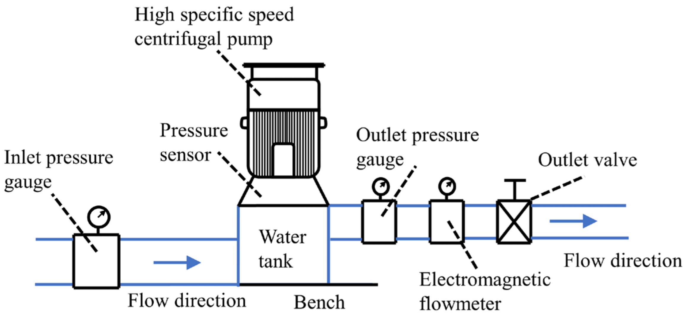
3.1. Test Bench Construction

The performance tests with different impellers, which have three and six blades, were carried out on a comprehensive experimental platform with Class II accuracy. The test bench is depicted in Figure 5, with inlet and outlet valves, inlet and outlet pressure gauges, and pressure transducers being included. Measurement accuracy is 0.5% for electromagnetic flow meters and inlet and outlet pressure gauges. The data were collected and transferred to the computer, and the performance of the pump was calculated.

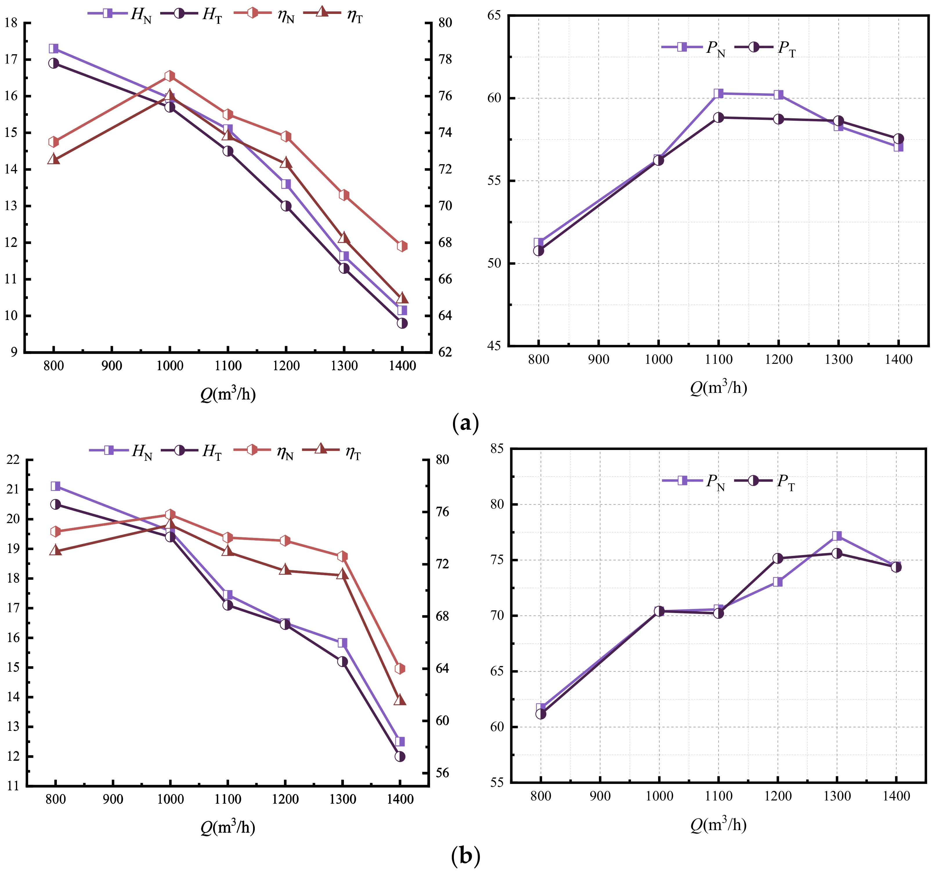
3.2. Comparison and Analysis of Test Results and Numerical Simulation Data

Figure 6 shows the numerical results and the experimental results with different blade numbers. The predicted values of head are slightly higher than the test values for most operating conditions, as is the efficiency. The higher predicted values of head at low flow conditions are due to uneven internal flow at low flow conditions. As the flow rate becomes larger, the relationship between predicted and tested values stabilizes. When the flow rate reaches 1300 m3/h, the head and efficiency values show a large deviation from the test values. This may be the result of the inevitable cavitation that occurs with high flows. As a whole, there is a good agreement between the numerical results and the experimental results.

4. Results and Discussion

4.1. Flow Field Characteristics of Centrifugal Pumps under Different Operating Conditions

The velocity distribution from the inlet to the impeller section at different flow conditions is depicted in Figure 7. Smooth velocity changes at different large flow conditions and uniform velocity distribution from the inlet to the impeller shaft surface. The velocity from the fluid inlet channel to the axial surface of the impeller increases with the increase in flow rate, but the increase is only about 20%. At the inlet of the impeller, a small high-speed area could be observed. This is due to the curved fluid on the wall creating a vortex here. This indicates that the flow pattern in the inlet section is good under different flow conditions. However, under large flow condition, the flow structure at the impeller inlet is damaged due to the disturbance of rotating blades, which could generate a large amount of energy loss.
The velocity and flow distribution of the mid-section in the volute under different operating conditions is depicted in Figure 8. There is a high-speed area in the impeller flow channel, and it can be seen that the speed of the blade suction surface in the impeller flow channel is greater than the pressure surface. When the flow rate was increased, it was found that the range of velocity variation around the impeller was not very large. Under the flow conditions of 1100 and 1300 m3/h, the velocity distribution at the volute outlet is uneven. There is a low-speed zone at frame A, which expands from the right to the left with the increase in flow. The speed streamline in frame B is also gradually disordered. This shows that there is a trend of flow separation within the volute under large flow conditions, which may lead to further loss of energy.
Figure 9 depicts the turbulent kinetic energy distribution in the middle section of the volute. The results show that compared with the internal velocity distribution, the variation range of turbulent kinetic energy in the volute is large. When the flow rate is 800 m3/h, the value of turbulent kinetic energy is large. Most areas in the volute are 1.5 m2/s2, of which the larger value is 4.0 m2/s2 outside the volute, as shown in box A. As the flow rate gradually increases, the turbulent energy values on the outside of the volute gradually decrease, while the turbulent energy values at the inlet gradually increase. When the flow reaches 1100 m3/h, the turbulence intensity of the volute becomes uniform. This indicates that the flow is not complicated at this time, and the energy loss is small. However, the turbulence kinetic energy at the outlet is large, as depicted in box B. This is consistent with the velocity distribution under the large flow condition, which verifies that the internal flow at the inlet under the large flow condition is complex and requires in-depth study.
The total pressure distribution in the impeller mid-section for different flow conditions is depicted in Figure 10. Obviously, within the impeller, the total pressure is evenly distributed, and there is no significant change in the size, while the total pressure distribution in the volute is uneven. When the flow rate is 800 and 1100 m3/h, the relative high pressure appears at the volute near the impeller, and most of the high-pressure values reach 300 kPa. With the increase in flow rate, the pressure value inside the volute decreases, and the pressure value distribution is still uneven. The area with high pressure in the volute near the impeller decreases, and the area with low pressure in the impeller flow passage decreases relatively. Under the flow condition of 1100 m3/h, a large range of high pressure appears at the volute near the impeller. A comparison of the total pressure diagrams for the four different flow conditions shows that there is no significant change in the impeller when the flow rate becomes larger. While the impeller low pressure range is reduced, the total pressure value in the volute is also reduced.
The cavitation number is defined as:
σ = ( p i n p v ) / 0.5 ρ u 2
where pin is the pressure at the pump inlet (Pa); pv is the saturated vapor pressure (Pa) corresponding to clean water at 25 °C.
The development of cavitation in the centrifugal pump could lead to hydraulic loss, which in turn leads to the deterioration of pump performance in two aspects. On the one hand, the cavitation structure blocks the flow channel, leading to changes in the flow pattern within the pump, which directly causes hydraulic losses. On the other hand, the cavitation structure induces the pressure fluctuation near the blade surface and the generation of vortex structure within the flow channel, which affects the work ability of the blade and leads to head loss. In order to analyze the cavitation morphology in the impeller of a high-specific-speed centrifugal pump under different working conditions, four different flows are selected in this paper to study the bubble distribution when the cavitation number is 0.55, as shown in Figure 11. According to the numerical results, when the flow rate is 500 m3/h, the pump head drops by less than 1%. At this time, the centrifugal pump is in the initial stage of cavitation. It can be seen that only a small range of cavitation is generated at the leading edge (LE) of the blade inlet during the initial stage of cavitation. As shown by the red dotted line in the figure, the blade is used to compare the change of cavitation under different flow rates. It was found that with the increase in flow rates, a large range of cavitation attachment appears on the back of the blade, and the cavitation thickness gradually increases. When Q = 110 m3/h, the cavitation volume occupies the edge of the blade, which affects the performance of the pump. This shows that cavitation can easily occur under large flow conditions, which may also be the reason for large deviation between the numerical results and the test results under large flow conditions.

4.2. Flow Field Characteristics of Centrifugal Pumps with Different Blade Numbers under Large Flow Conditions

Figure 12 illustrates the distribution of the vapor pocket volume for the different number of impeller blades at a cavitation number of 0.55 and a flow rate of 1300 m3/h. The cavitation around the blade inlet edge is clearly visible with three blades. The cavitation is most severe under these conditions, especially with the largest cavitation volume of A2. With the increase in blade numbers, the cavitation area of the blade decreases with the same cavitation number and flow rate. The main cavitation places are at the leading edge of the blade, where the curvature is relatively large, and it is easy to collide with the water flow. When the number of blades is five, the cavitation volume at A4 is 0, indicating that when the number of blades increases, the cavitation degree at the blade edge will decrease. The cavitation of three blades is relatively serious, which will have a great impact on the performance of the pump. Therefore, when considering cavitation under large flow conditions, the impact of blade numbers on cavitation should be considered.
Figure 13 shows the velocity distribution of the sections with different impeller blade numbers at 1300 m3/h. It is obvious from the figure that when the blade number is small, there is a low-speed area at the inlet of the volute, and the flow velocity near the impeller is larger. With the increase in the blade number, the low-speed area at the volute inlet is significantly reduced. At the same time, the speed of the impeller decreases slightly. Generally, the larger speed of the impeller is concentrated in the flow passage, which is generally about 13 m/s, and the speed in other areas is relatively uniform. Therefore, the increase in blade number is conducive to improving the flow pattern distribution near the volute inlet and impeller and to reducing the internal energy loss of the pump.
Figure 14 depicts the distribution of turbulent kinetic energy in the middle section of the centrifugal pump with different numbers of blades when the flow is 1300 m3/h. When the number of blades is increased, the turbulent kinetic energy in the impeller is basically unchanged, while it changes regularly in the volute. Specifically, the turbulent kinetic energy on the outer side of the volute increases rapidly and unevenly, while the relative increase on the inner side is gentle. When the number of impeller blades is three and four, the turbulent kinetic energy in some areas increases sharply at the outlet of the volute. The maximum value of 4.0 J/kg indicates that this part of the flow is more complex and has a higher energy loss. When the number of impeller blades is four and five, most areas in the volute reach 1.5 J/kg. Under the number of six blades, the turbulent kinetic energy value is small, and the distribution of impeller and volute is relatively uniform. The turbulent energy changes of different blade numbers under large flow conditions further show that the reasonable increase in impeller blade numbers can improve the internal flow structure under large flow conditions and improve the operational stability of the pump.
Figure 15 depicts the total pressure distribution in the middle section with different blade numbers when the flow is 1300 m3/h. It is obviously observed that, from the impeller inlet to the whole impeller fluid domain, the fluid pressure basically has no change. However, lower pressures occur near the impeller blades. The total pressure distribution in the volute is not uniform and has a wide range of variation. The relatively high pressure appears near the volute near the impeller, and some areas reach 350 kPa. With the increase in the number of blades, the pressure value inside the volute increases continuously, and the pressure value distribution is still uneven. At this point, the area of lower pressure in the impeller runners is relatively reduced.

5. Conclusions

In this paper, the internal flow characteristics of a high-specific-speed centrifugal pump with different blade numbers are investigated under large flow conditions. Measurements have been conducted to verify the numerical predictions. The conclusions are as follows:
(1)
The measurements and the prediction have good overall agreement and permissible errors.
(2)
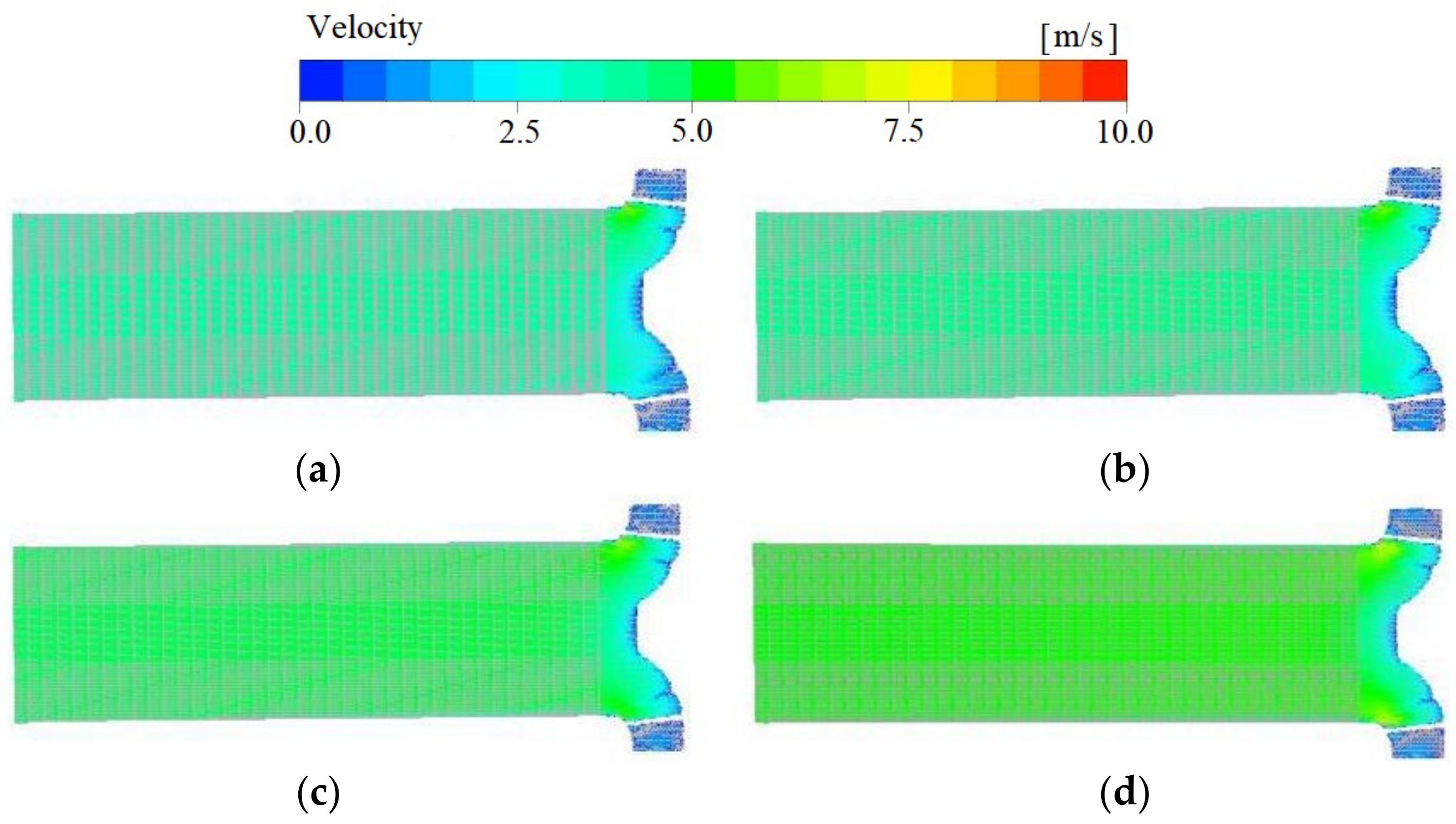
The results also show that when the flow rate increases, the inlet runner velocity increases. However, the speed of the impeller inlet is significantly reduced, and backflow occurs. The results show that the cavitation volume increases with the increase in flow rate, implying that significant cavitation occurs with higher flowrates. At high flow rate conditions, it is also observed that the velocity distribution at the outlet of the volute becomes unevenly chaotic, resulting in decreasing turbulent energy at the inlet of the volute. Hence, under a higher flowrate condition, this shows that the internal flow state is disordered and the operation is unstable.
(3)
When the number of blades is six, the range of turbulent energy variations inside the impeller is low. The low-pressure range of the impeller runners is reduced, and the turbulent energy on the inside of the worm gear remains unchanged. At the same time, the degree of cavitation in the pump decreases with the increase in the blade numbers. Therefore, an appropriate selection of the blade number is important to improve the internal flow condition of the pump.

Author Contributions

Data curation, C.W. and X.C.; formal analysis, Q.Z. and W.C.; writing—original draft, Q.Z. and C.W.; writing—review and editing, J.G. and Y.Z.; software, H.C. All authors have read and agreed to the published version of the manuscript.

Funding

This research was supported by the National Natural Science Foundation of China (Grant No: 51979240 and 52009013), and the National Key R&D Program of China (Grant No: 2020YFC1512402).

Data Availability Statement

Not applicable.

Conflicts of Interest

The authors declare no conflict of interest.

References

  1. Hoang, T.; Truong, V.; Shrestha, U.; Choi, Y. Optimization of the Meridional Plane Shape Design Parameters in a Screw Centrifugal Pump Impeller. Proc. Korea Fluid Mach. Soc. 2021, 24, 15–25. [Google Scholar] [CrossRef]
  2. Shen, Z.; Chu, W. Influence of grooves arrangement in volute casing on internal flow characteristics of centrifugal pump. J. Huazhong Univ. Sci. Technol. 2019, 47, 37–42. [Google Scholar] [CrossRef]
  3. Tang, S.; Zhu, Y.; Yuan, S. Intelligent fault identification of hydraulic pump using deep adaptive normalized CNN and syn-chrosqueezed wavelet transform. Reliab. Eng. Syst. Saf. 2022, 224, 108560. [Google Scholar] [CrossRef]
  4. Yang, Y.; Zhou, L.; Zhou, H.; Lv, W.; Wang, J.; Shi, W.; He, Z. Optimal design of slit impeller for low specific speed centrifugal pump based on orthogonal test. J. Mar. Sci. Eng. 2021, 9, 121. [Google Scholar] [CrossRef]
  5. Xi, B.; Wang, C.; Xi, W.; Liu, Y.; Wang, H.; Yang, Y. Experimental investigation on the water hammer characteristic of stalling fluid in eccentric casing-tubing annulus. Energy 2022, 253, 124113. [Google Scholar] [CrossRef]
  6. Guo, X.; Zhu, L.; Zhu, Z.; Cui, B.; Li, Y. Numerical and experimental investigations on the cavitation characteristics of a high-speed centrifugal pump with a splitter-blade inducer. J. Mech. Sci. Technol. 2015, 29, 259–267. [Google Scholar] [CrossRef]
  7. Skrzypacz, J.; Bieganowski, M. The influence of micro grooves on the parameters of the centrifugal pump impeller. Int. J. Mech. Sci. 2018, 144, 827–835. [Google Scholar] [CrossRef]
  8. Xue, R.; Lin, X.; Zhang, B.; Zhou, H.; Lai, T.; Hou, Y. CFD and Energy Loss Model Analysis of High-Speed Centrifugal Pump with Low Specific Speed. Appl. Sci. 2022, 12, 7435. [Google Scholar] [CrossRef]
  9. Hao, Y.; Hao, J.; Zhu, Z.; Su, X.; Lu, W.; Gruszczynski, M.; Ding, Q.; Panlong, G. Review of the Hydraulic and Structural Design of High-Speed Centrifugal Pumps. Front. Energy Res. 2022, 10. [Google Scholar] [CrossRef]
  10. Ding, H.; Li, Z.; Gong, X.; Li, M. The influence of blade outlet angle on the performance of centrifugal pump with high specific speed. Vacuum 2019, 159, 239–246. [Google Scholar] [CrossRef]
  11. Cheng, X.; Chang, Z.; Jiang, Y. Study on the influence of the specific area of balance hole on cavitation performance of high-speed centrifugal pump. J. Mech. Sci. Technol. 2020, 34, 3325–3334. [Google Scholar] [CrossRef]
  12. Huan, Y.; Liu, Y.; Li, X.; Zhu, Z.; Qu, J.; Zhe, L.; Han, A. Experimental and numerical investigations of cavitation evolution in a high-speed centrifugal pump with inducer. J. Hydrodyn. 2021, 33, 140–149. [Google Scholar] [CrossRef]
  13. Ge, M.; Manikkam, P.; Ghossein, J.; Subramanian, R.; Coutier-Delgosha, O.; Zhang, G. Dynamic mode decomposition to classify cavitating flow regimes induced by thermodynamic effects. Energy 2022, 254, 124426. [Google Scholar] [CrossRef]
  14. Gangipamula, R.; Ranjan, P.; Patil, S. Flow-induced noise sources and reduction methods in centrifugal pumps: A literature review. Phys. Fluids 2022, 34, 081302. [Google Scholar] [CrossRef]
  15. Hu, B.; Yao, Y.; Wang, M.; Wang, C.; Liu, Y. Flow and Performance of the Disk Cavity of a Marine Gas Turbine at Varying Nozzle Pressure and Low Rotation Speeds: A Numerical Investigation. Machines 2023, 11, 68. [Google Scholar] [CrossRef]
  16. Ge, M.; Petkovšek, M.; Zhang, G.; Jacobs, D.; Coutier-Delgosha, O. Cavitation dynamics and thermodynamic effects at elevated temperatures in a small Venturi channel. Int. J. Heat Mass Transf. 2021, 170, 120970. [Google Scholar] [CrossRef]
  17. Zhang, J.; Yang, H.; Liu, H.; Xu, L.; Lv, Y. Pressure Fluctuation Characteristics of High-Speed Centrifugal Pump with Enlarged Flow Design. Processes 2021, 9, 2261. [Google Scholar] [CrossRef]
  18. Chao, Q.; Zhang, J.; Xu, B.; Huang, H.; Zhai, J. Centrifugal effects on cavitation in the cylinder chambers for high-speed axial piston pumps. Meccanica 2019, 54, 815–829. [Google Scholar] [CrossRef]
  19. Wang, S.; Chen, X.; Li, X.; Cui, B.; Zhu, Z. Weak compressibility effects on the pressure fluctuation at RSI in a high speed centrifugal pump. J. Mech. Sci. Technol. 2022, 36, 5047–5057. [Google Scholar] [CrossRef]
Figure 1. Impeller and volute hydraulic model diagram: (a) impeller; (b) volute.
Machines 11 00138 g001
Figure 2. Three-dimensional diagram of high specific speed centrifugal pump.
Machines 11 00138 g002
Figure 3. Centrifugal pump grid diagram: (a) impeller; (b) volute.
Machines 11 00138 g003
Figure 4. The grid independence analysis.
Machines 11 00138 g004
Figure 5. Schematic diagram of external characteristic test bench.
Machines 11 00138 g005
Figure 6. Comparison of performance between CFD prediction and experiment: (a) three-blade; (b) six-blade. Note: H, η and P represent head (m), efficiency (%) and power (kw), respectively. Subscripts N and T represent numerical calculated value and test value, respectively.
Machines 11 00138 g006
Figure 7. Relative velocity vectors in the axial section of the pump at different flow rates: (a) 800 m3/h; (b) 1000 m3/h; (c) 1100 m3/h; (d) 1300 m3/h.
Machines 11 00138 g007
Figure 8. Velocity and streamline distribution of the volute at different flow rates: (a) 800 m3/h; (b)1000 m3/h; (c) 1100 m3/h; (d) 1300 m3/h.
Machines 11 00138 g008
Figure 9. Turbulence kinetic energy in pump cross-section at different flow rates: (a) 800 m3/h; (b) 1000 m3/h; (c) 1100 m3/h; (d) 1300 m3/h.
Machines 11 00138 g009
Figure 10. The total pressure in pump cross-section at different flow rates: (a) 800 m3/h; (b) 1000 m3/h; (c) 1100 m3/h; (d) 1300 m3/h.
Machines 11 00138 g010
Figure 11. Cavitation distribution under different working conditions: (a) 500 m3/h; (b) 800 m3/h; (c) 1000 m3/h; (d) 1100 m3/h.
Machines 11 00138 g011
Figure 12. Cavitation volume distribution with different numbers of blades: (a) three-blade; (b) four-blade; (c) five-blade; (d) six-blade. Note: The setting angle of impeller blade inlet is 22°.
Machines 11 00138 g012
Figure 13. Relative velocity vectors in pump cross-section at different numbers of blades: (a) three-blade; (b) four-blade; (c) five-blade; (d) six-blade.
Machines 11 00138 g013aMachines 11 00138 g013b
Figure 14. Turbulence kinetic energy in pump cross-section at different numbers of blades: (a) three-blade; (b) four-blade; (c) five-blade; (d) six-blade.
Machines 11 00138 g014
Figure 15. The total pressure in pump cross-section at different numbers of blades: (a) three-blade; (b) four-blade; (c) five-blade; (d) six-blade.
Machines 11 00138 g015
Disclaimer/Publisher’s Note: The statements, opinions and data contained in all publications are solely those of the individual author(s) and contributor(s) and not of MDPI and/or the editor(s). MDPI and/or the editor(s) disclaim responsibility for any injury to people or property resulting from any ideas, methods, instructions or products referred to in the content.

