
Construction Method of Digital Twin System for Thin-Walled Workpiece Machining Error Control Based on Analysis of Machine Tool Dynamic Characteristics
Abstract
:1. Introduction
2. A Digital Twin System Architecture for Evolvable Machine Tools
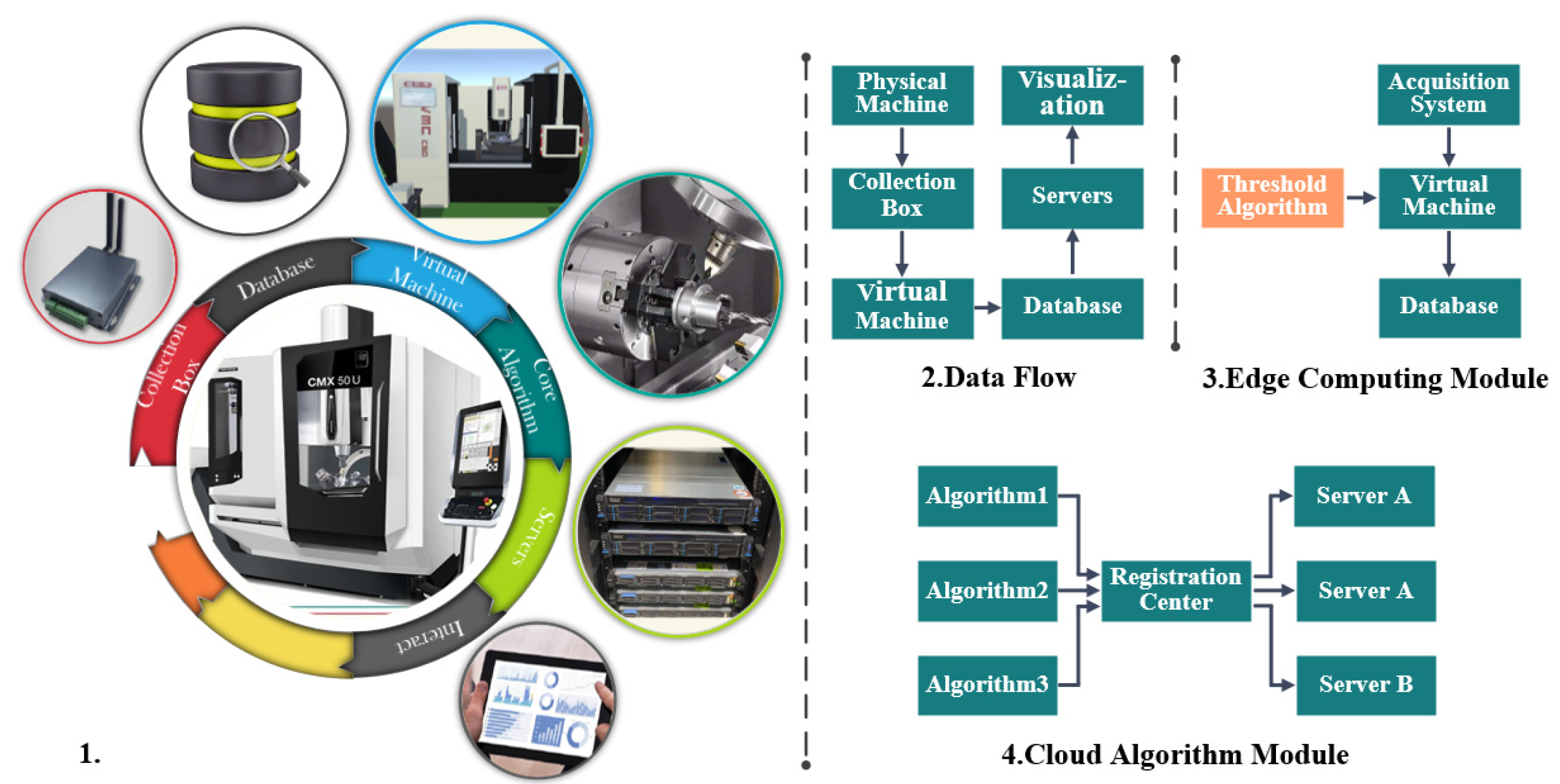
2.1. Basic Structure
2.2. Architecture Design to Reduce Coupling
3. Functional Module Development
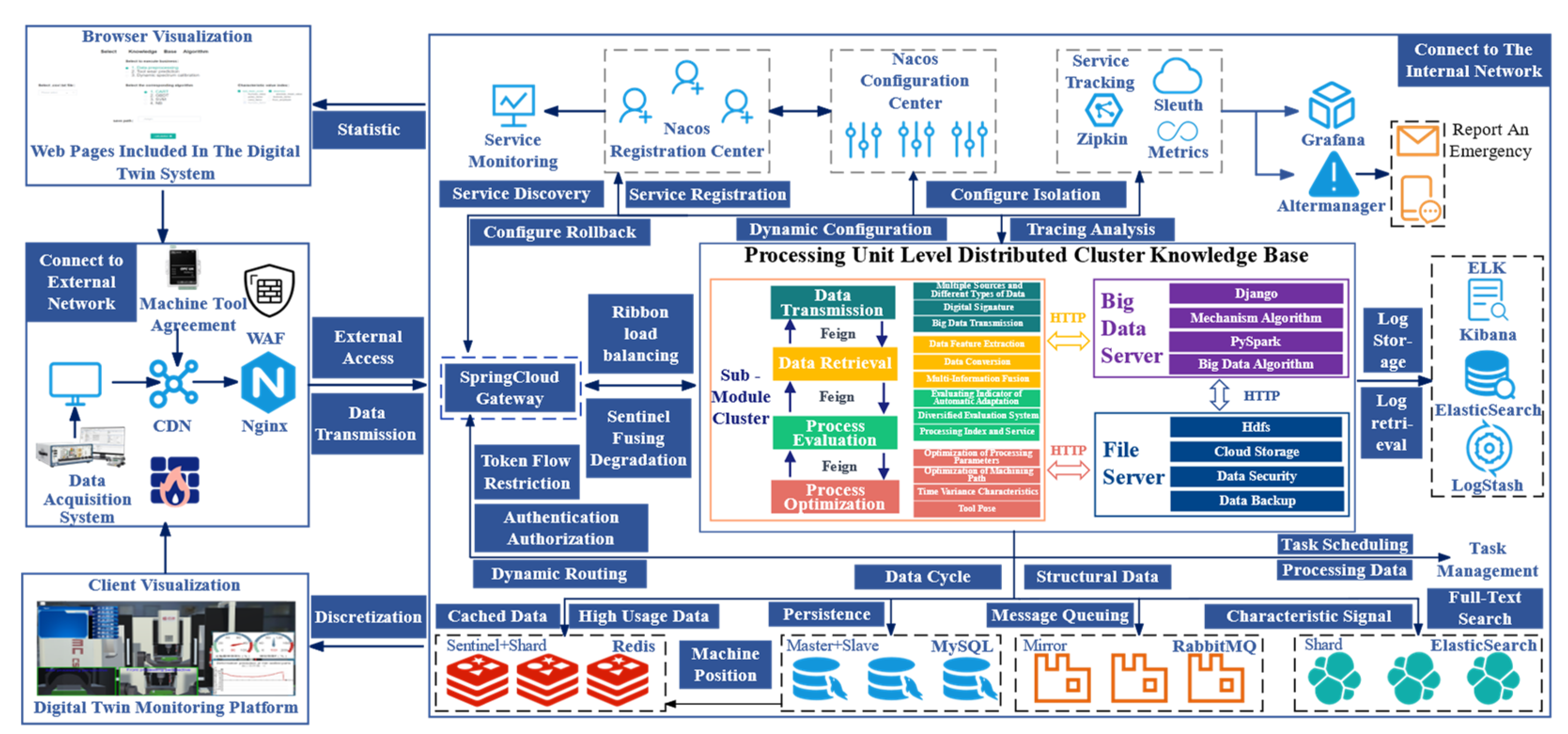
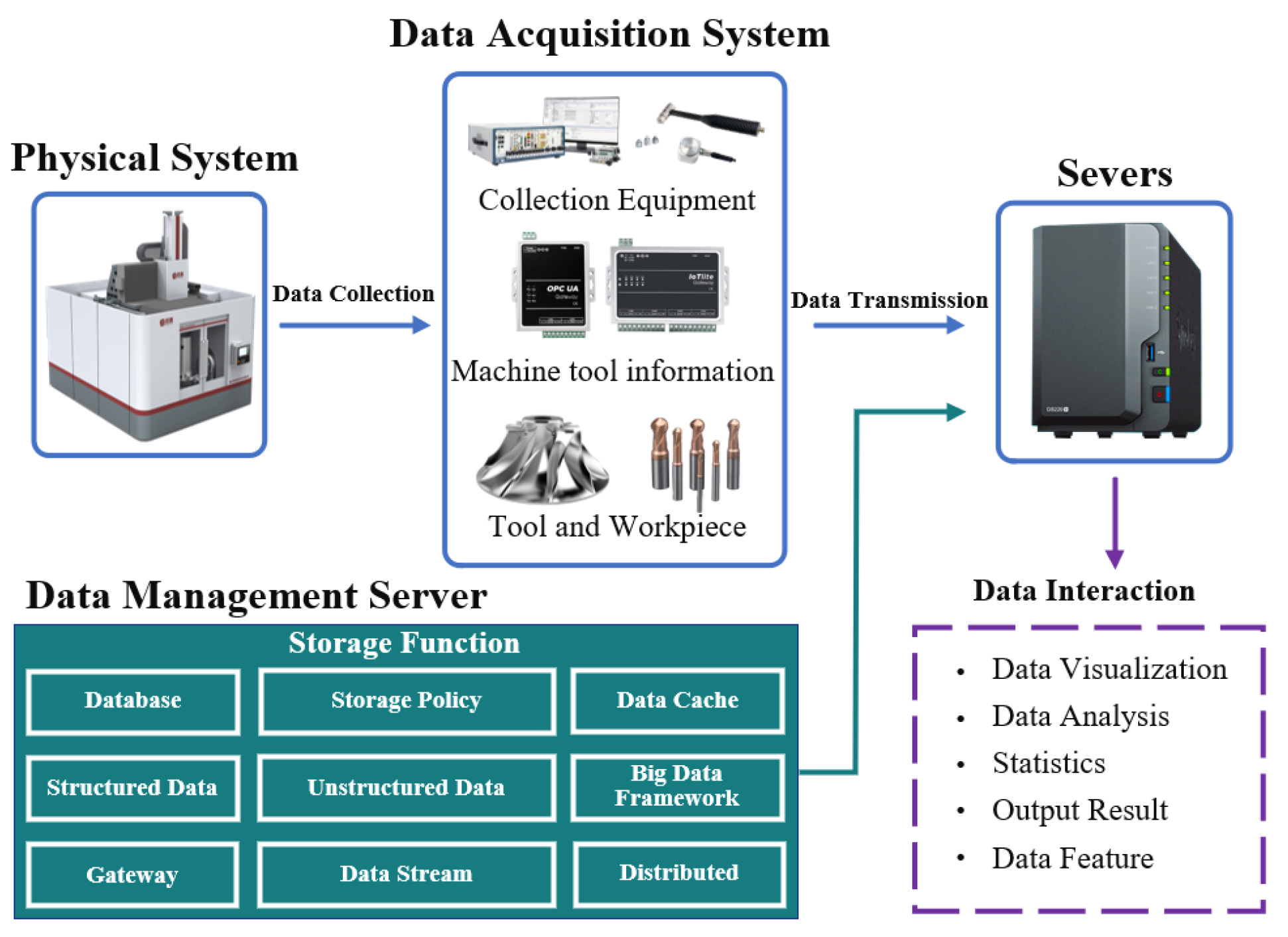
3.1. Data Acquisition and Transmission Module of Digital Twin System
3.2. Digital Twin System Algorithm Module
3.3. Processing Unit Processing Process Evaluation Module
3.4. Processing Unit Processing Process Optimization Module
3.5. Visualization Module
4. Experiment and Analysis
4.1. Experiment and Simulation
4.2. Knowledge Base Server Construction and Tool Path Evaluation Algorithm Embedding
4.2.1. Embedding Three Types of Kriging Algorithms into the Knowledge Base
4.2.2. Cutting Parameter Optimization Algorithm Embedded in Knowledge Base
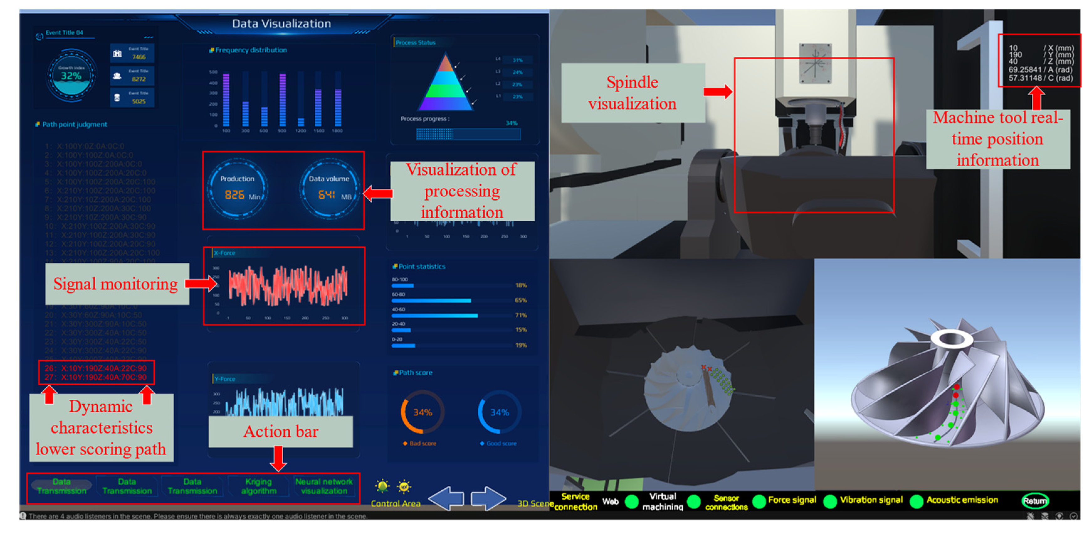
4.3. Visualization Interface of Processing Unit Digital Twin System
4.4. Cutting Experiment Verification
5. Conclusions
- In response to the intelligent processing needs of aviation thin-walled parts, a dynamic characteristic digital twin system building method for thin-walled machining units was proposed by combining digital twin technology and microservice technology. The method aimed to gradually build a complete information communication process starting from data collection, transmission, and processing, and to reduce system coupling as much as possible from the design stage of the twin system.
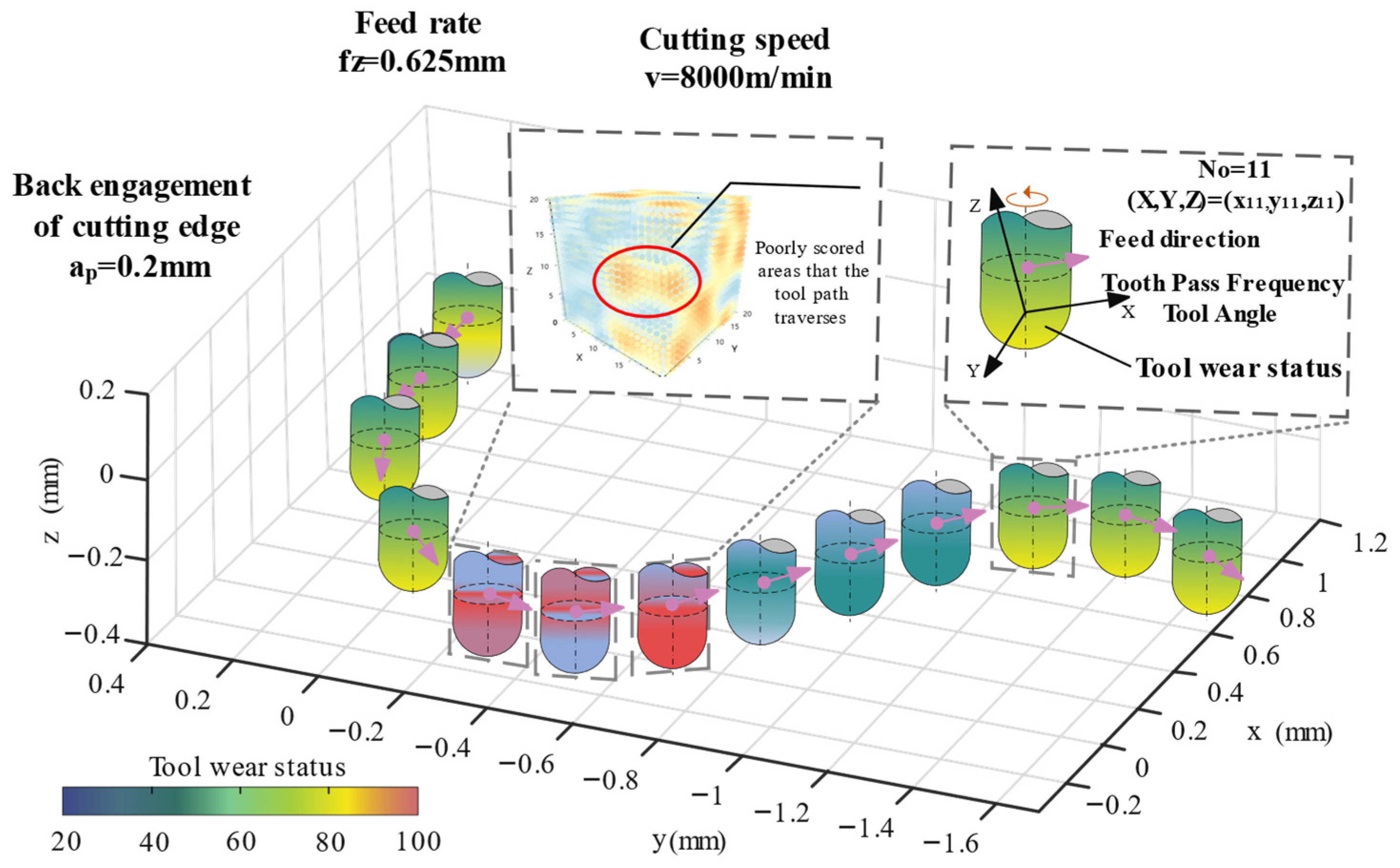
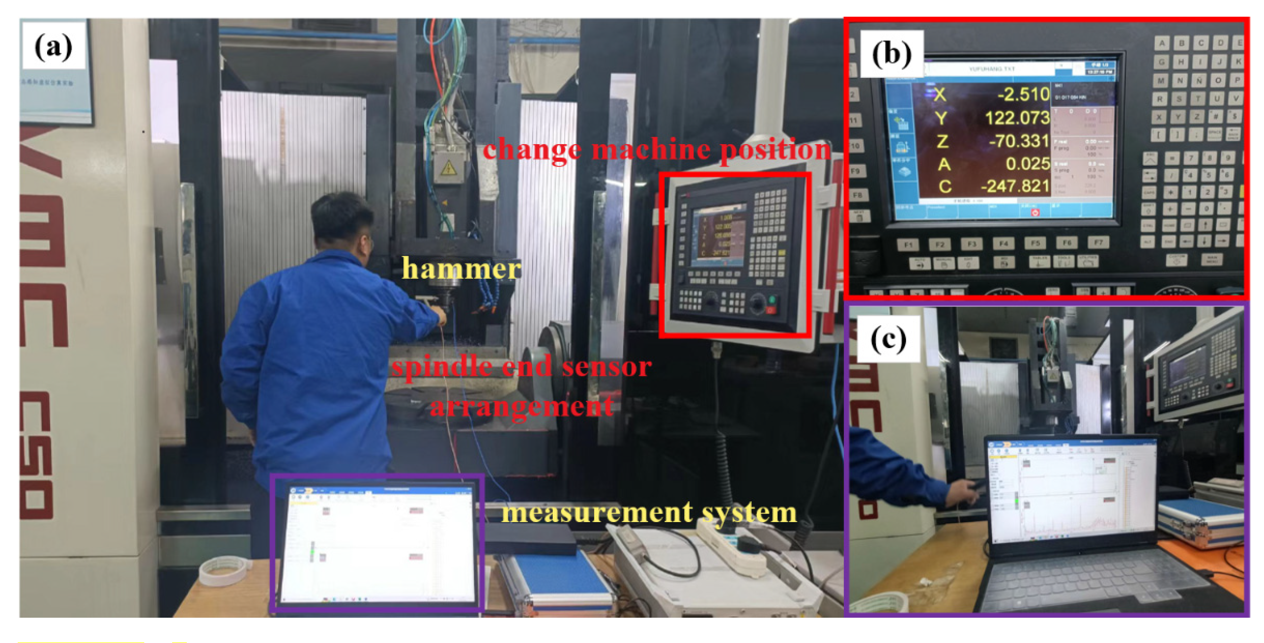
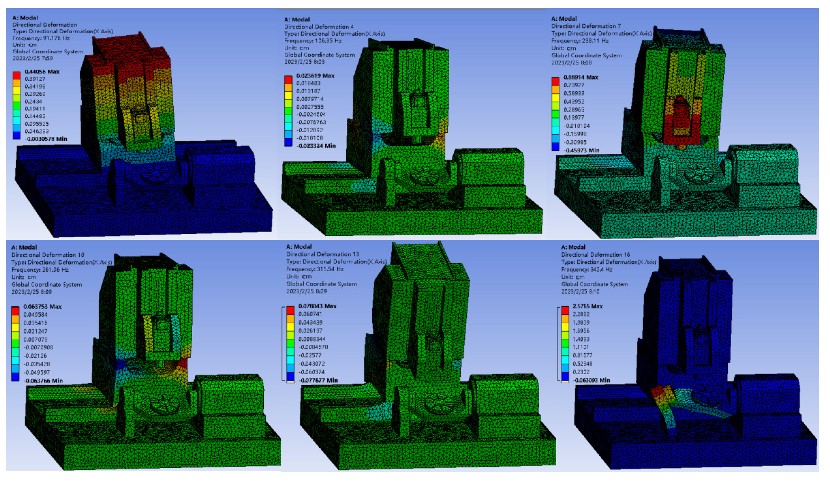
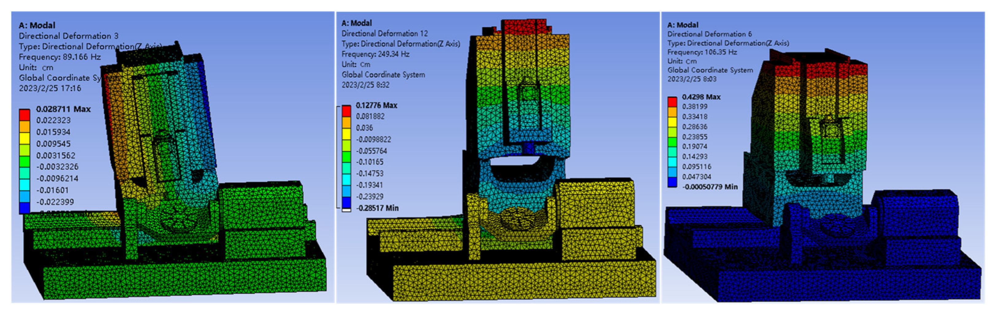
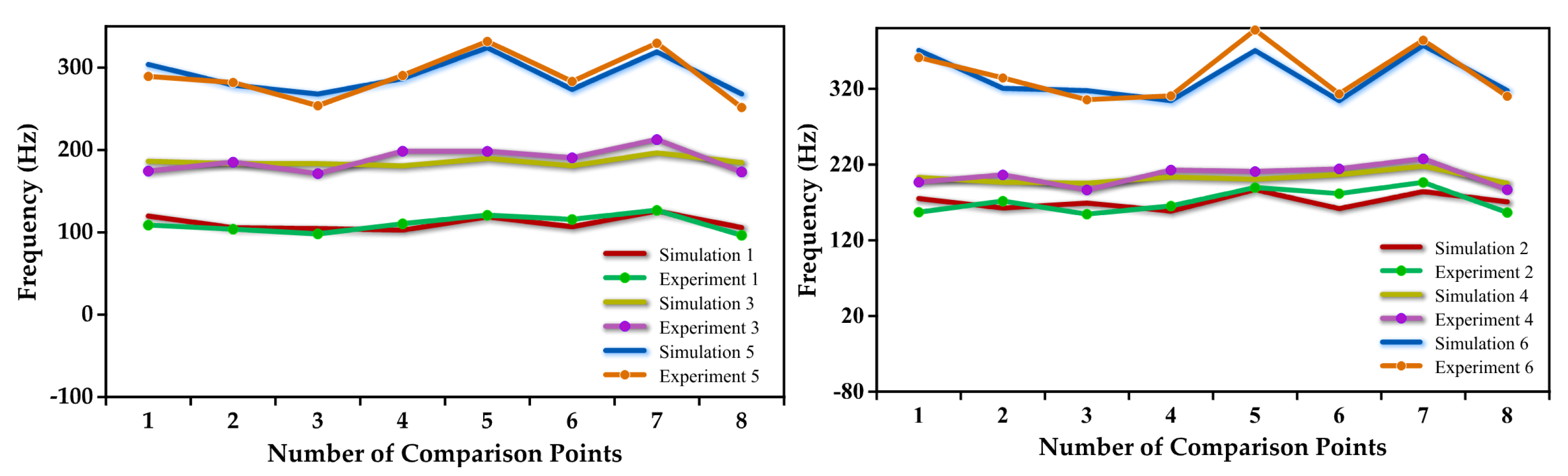
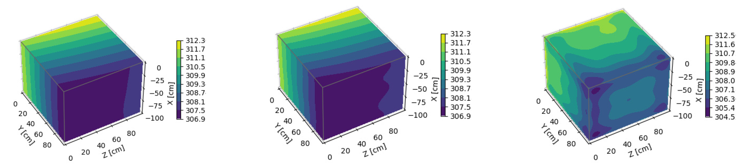
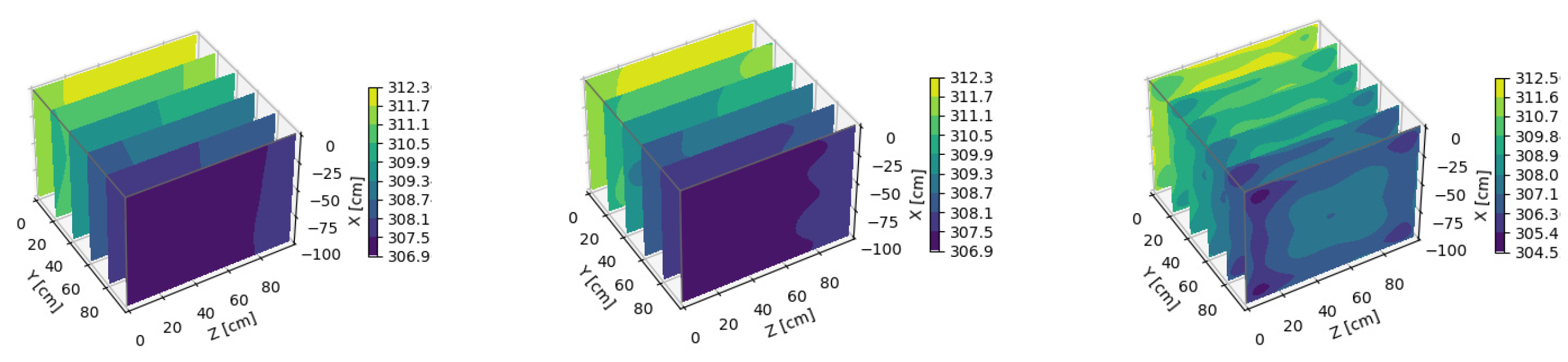
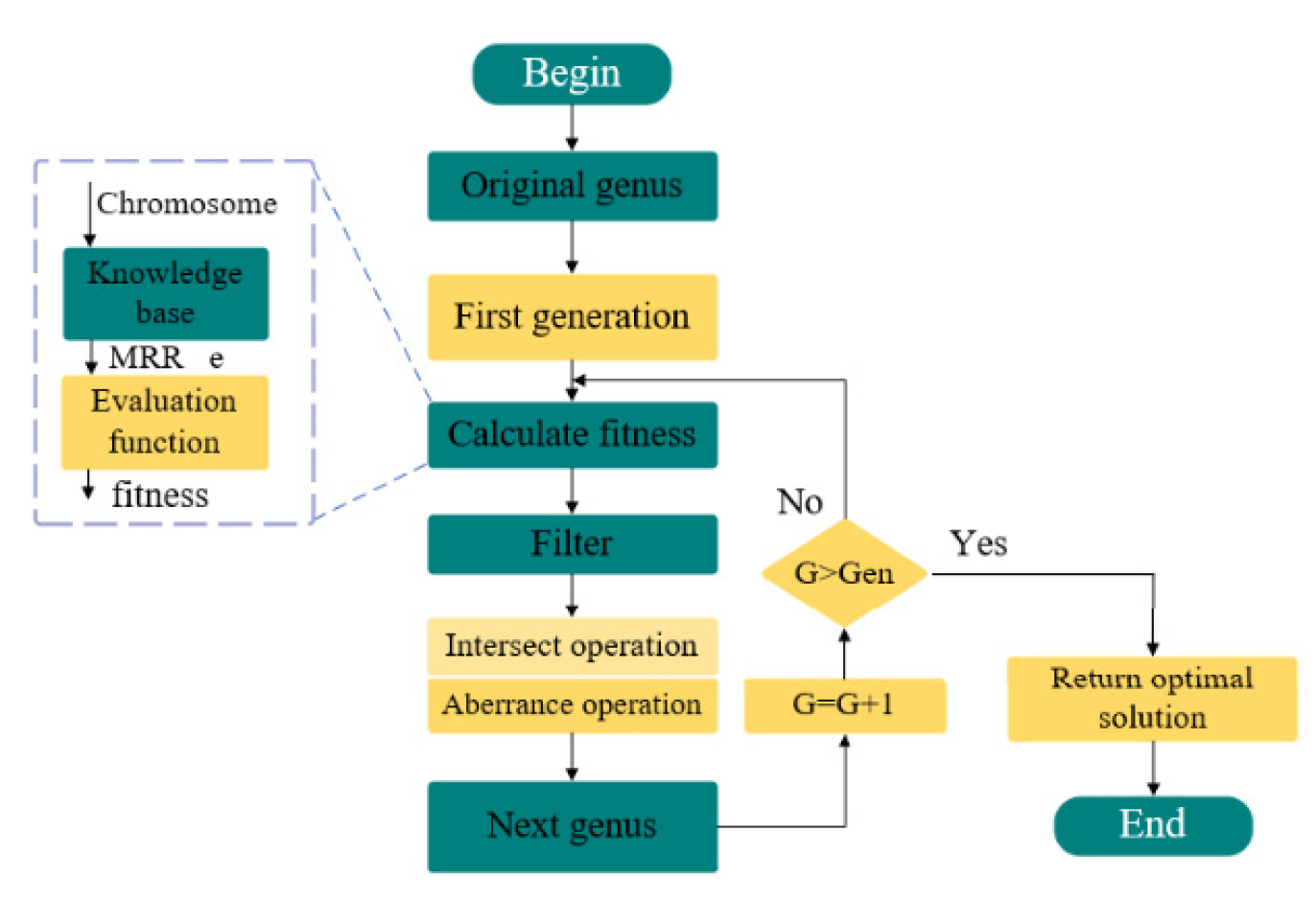
- By simulation and experimental methods, dynamic characteristic data at different positions and orientations of the machine tool were obtained, and the dynamic data were used as the input of the digital twin system to support the optimization of thin-walled machining parameters. On the basis of the established data loop of the digital twin system, the Kriging method was used to analyze the change rules of the relative spatial position of the machine tool spindle and the swivel table angle by establishing a knowledge base for calibrating the time-varying dynamic characteristic spectrum of the machine tool, and a set of evaluation and optimization strategies based on the digital twin system was proposed for thin-walled machining.
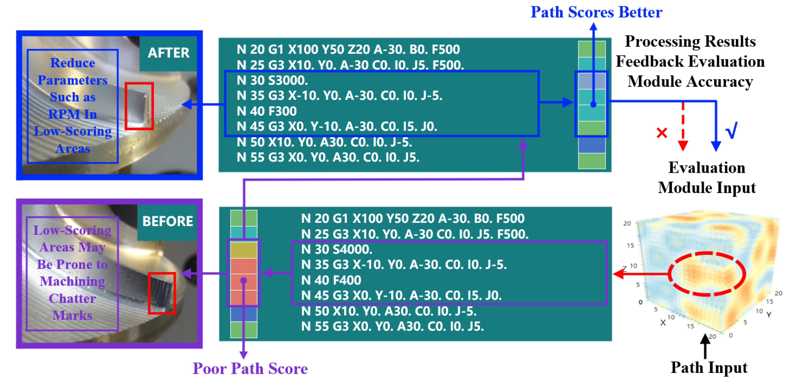
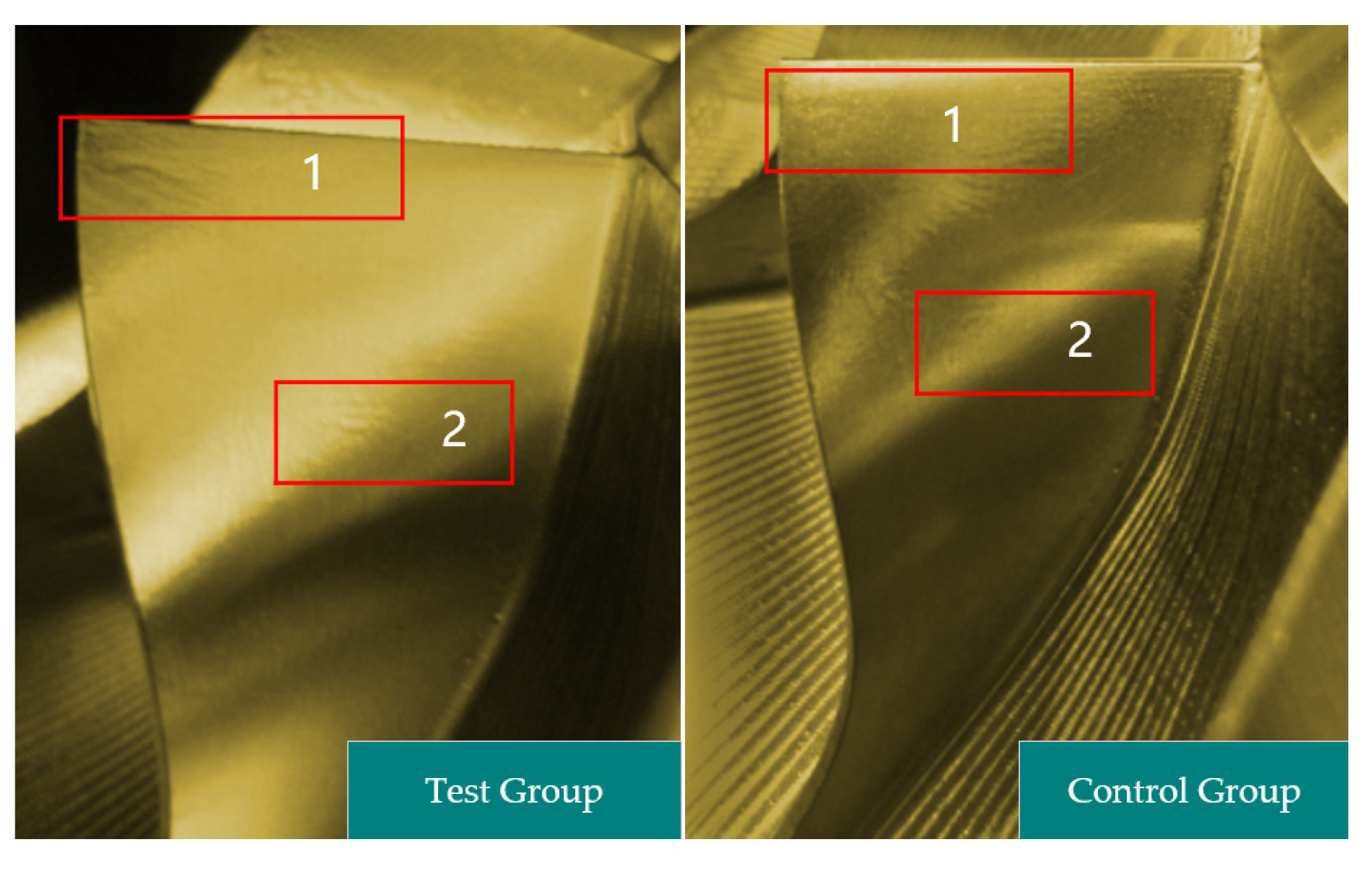
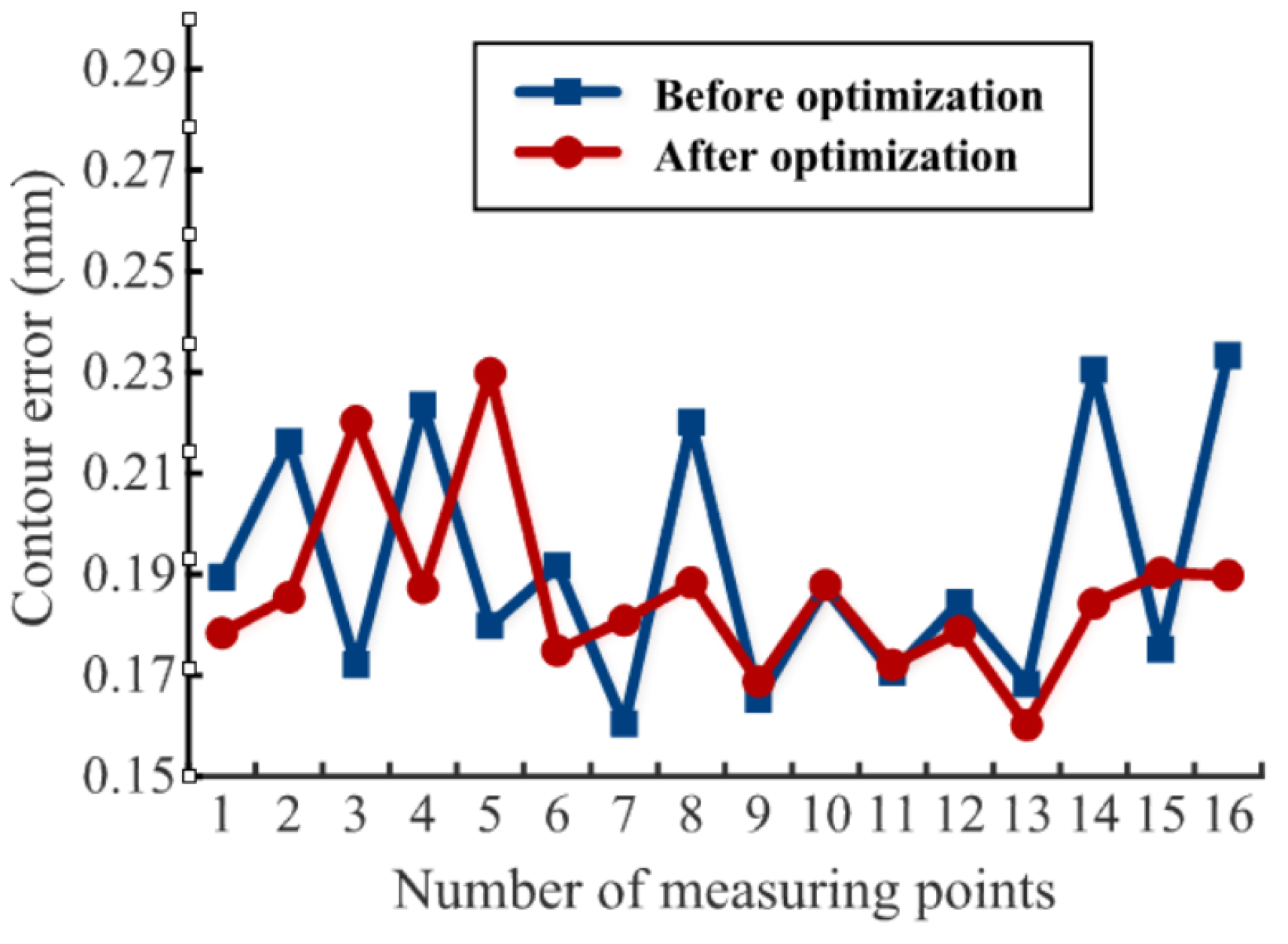
- A traceable optimization scheme for thin-walled machining parameters and processes was proposed for poorly machined areas, and the maximum deviation of the machining contour of the impeller was reduced from 0.2333 mm to 0.2298 mm after optimization. The average machining contour error of the impeller detected after the proposed method optimization was reduced by 18.75%, which verified the effectiveness of the proposed method.
Author Contributions
Funding
Institutional Review Board Statement
Informed Consent Statement
Data Availability Statement
Conflicts of Interest
References
- Wu, G.; Li, G.; Pan, W.; Raja, I.; Wang, X.; Ding, S. A state-of-art review on chatter and geometric errors in thin-wall machining processes. J. Manuf. Process. 2021, 68, 454–480. [Google Scholar] [CrossRef]
- Sun, Y.; Zheng, M.; Jiang, S.; Zhan, D.; Wang, R. A State-of-the-Art Review on Chatter Stability in Machining Thin−Walled Parts. Machines 2023, 11, 359. [Google Scholar] [CrossRef]
- Wu, W.; Liu, Q. Extended transfer matrix method for dynamic modeling of machine tools. J. Mech. Eng. 2010, 46, 69–75. [Google Scholar] [CrossRef]
- Liu, Y.; Zhang, Q.; Zhao, X.; Zhang, Z.; Zhang, Y. Machining center based on multibody theory model thermal error compensation technology. J. Mech. Eng. 2002, 38, 127–130. [Google Scholar] [CrossRef]
- Zhao, W.; Du, C.; Zhang, J.; Liu, H. Analytical modeling method of dynamics for the spindle rotor system. J. Mech. Eng. 2013, 49, 44–51. [Google Scholar] [CrossRef]
- Li, T.; Ding, X.; Cheng, K. Machine tool dynamics based on spatial statistics. J. Mech. Eng. 2015, 51, 87–94. [Google Scholar] [CrossRef]
- Yang, S.; Wang, L.; Liao, Q.; Liang, F.; Yin, G. Study on the spatial dynamic performance of five-axis NC machine tool based on radial basis function method. J. Mech. Eng. 2019, 55, 144–153. [Google Scholar] [CrossRef]
- Zaghbani, I.; Songmene, V. Estimation of machine-tool dynamic parameters during machining operation through operational modal analysis-ScienceDirect. Int. J. Mach. Tools Manuf. 2009, 49, 947–957. [Google Scholar] [CrossRef]
- da Silva, M.M.; Brüls, O.; Swevers, J.; Desmet, W.; Van Brussel, H. Computer-aided integrated design for machines with varying dynamics. Mech. Mach. Theory 2009, 44, 1733–1745. [Google Scholar] [CrossRef]
- Altintas, Y.; Brecher, C.; Weck, M.; Witt, S. Virtual machine tool. Cirp. Ann.-Manuf. Technol. 2005, 54, 651–674. [Google Scholar] [CrossRef]
- Cao, Y.; Altintas, Y. Modeling of spindle-bearing and machine tool systems for virtual simulation of milling operations. Int. J. Mach. Tools Manuf. 2007, 47, 1342–1350. [Google Scholar] [CrossRef]
- Kolar, P.; Sulitka, M.; Janota, M. Simulation of dynamic properties of a spindle and tool system coupled with a machine tool frame. Int. J. Adv. Manuf. Technol. 2011, 54, 11–20. [Google Scholar] [CrossRef]
- Budak, E.; Kops, L. Improving productivity and part quality in milling of titanium based impellers by chatter suppression and force control. CIRP Ann.-Manuf. Technol. 2000, 49, 31–36. [Google Scholar] [CrossRef]
- Smith, S.; Tlusty, J. Efficient simulation programs for chatter in milling. CIRP Ann.-Manuf. Technol. 1993, 42, 463–466. [Google Scholar] [CrossRef]
- Wu, Y.; Wang, K.; Zheng, G.; Lv, B.; He, Y. Experimental and simulation study on chatter stability region of integral impeller with non-uniform allowance. Sci. Prog. 2020, 103, 36850420933418. [Google Scholar] [CrossRef] [PubMed]
- Lu, K.; Lian, Z.; Gu, F.; Liu, H. Model-based chatter stability prediction and detection for the turning of a flexible workpiece. Mech. Syst. Signal Process. 2018, 100, 814–826. [Google Scholar] [CrossRef]
- Ferry, W. Virtual five-axis flank milling of jet engine impellers. Univ. Br. Columbia 2008, 130, 339–353. [Google Scholar]
- Wang, X.; Song, Q.; Liu, Z. Position-dependent stability prediction for multi-axis milling of the thin-walled component with a curved surface. Appl. Sci. 2020, 10, 8779. [Google Scholar] [CrossRef]
- Qin, P.; Wang, M.; Sun, L. Feed rate variation strategy for semi-conical shell workpiece in ball head end milling process. Appl. Sci. 2020, 10, 9135. [Google Scholar] [CrossRef]
- Olvera, D.; Urbikain, G.; Elías-Zuñiga, A.; López de Lacalle, L.N. Improving stability prediction in peripheral milling of Al7075T6. Appl. Sci. 2018, 8, 1316. [Google Scholar] [CrossRef]
- Wang, P.; Bai, Q.; Cheng, K.; Zhao, L.; Ding, H. The modelling and analysis of micro-milling forces for fabricating thin-walled micro-parts considering machining dynamics. Machines 2022, 10, 217. [Google Scholar] [CrossRef]
- Grieves, M.; Vickers, J. Digital Twin: Mitigating Unpredictable, Undesirable Emergent Behavior in Complex Systems; Springer International Publishing: New York, NY, USA, 2017. [Google Scholar]
- Cheng, D.-J.; Zhang, J.; Hu, Z.-T.; Xu, S.-H.; Fang, X.-F. A digital twin-driven approach for on-line controlling quality of marine diesel engine critical parts. Int. J. Precis. Eng. Manuf. 2020, 21, 1821–1841. [Google Scholar] [CrossRef]
- Steringer, R.; Zörrer, H.; Zambal, S.; Eitzinger, C. Using discrete event simulation in multiple system life cycles to support zero-defect composite manufacturing in aerospace industry. IFAC-Pap. 2019, 52, 1467–1472. [Google Scholar] [CrossRef]
- Tong, X.; Liu, Q.; Pi, S.; Xiao, Y. Real-time machining data application and service based on IMT digital twin. J. Intell. Manuf. 2020, 31, 1113–1132. [Google Scholar] [CrossRef]
- Luo, W. Research on the Key Technology of Machine Tool Predictive Maintenance Based on Digital Twin; Shandong University: Jinan, China, 2020. [Google Scholar]
- Jiang, J. Research on Machining Path Optimization Method of CNC Machine Tools Based on Digital Twin; Wuhan University of Technology: Wuhan, China, 2019. [Google Scholar]
- Tao, F.; Liu, W.; Zhang, M.; Hu, T.L.; Qi, Q.; Zhang, H.; Sui, F.; Wang, T.; Xu, H.; Huang, Z. Five-dimension digital twin model and its ten applications. Comput. Integr. Manuf. Syst. 2019, 25, 1–18. [Google Scholar]
- Tao, F.; Zhang, M.; Cheng, J.; Qi, Q. Digital twin workshop: A new paradigm for future workshop. Comput. Integr. Manuf. Syst. 2017, 23, 1–9. [Google Scholar]
- Liu, J. Research on CNC System of Microservice Architecture for Cluster Deployment; Harbin Institute of Technology: Harbin, China, 2020. [Google Scholar]
- Ismail, B.I.; Goortani, E.M.; Ab Karim, M.B.; Tat, W.M.; Setapa, S.; Luke, J.Y.; Hoe, O.H. Evaluation of docker as edge computing platform. In Proceedings of the 2015 IEEE Conference on Open Systems (ICOS), Melaka, Malaysia, 24–26 August 2015; pp. 130–135. [Google Scholar]
- Medel, V.; Tolosana-Calasanz, R.; Bañares, J.Á.; Arronategui, U.; Rana, O.F. Characterising resource management performance in kubernetes. Comput. Electr. Eng. 2018, 68, 286–297. [Google Scholar] [CrossRef]
- Wiatr, R.; Sota, R.; Kitowski, J.; Elsevier, B. Optimising kafka for stream processing in latency sensitive systems. Procedia Comput. Sci. 2018, 136, 99–108. [Google Scholar] [CrossRef]
- Ritzi, R.W., Jr. Introduction to geostatistics: Applications in hydrogeology. Trans. Am. Geophys. Union. 1998, 79, 320. [Google Scholar] [CrossRef]
- Smith, S.; Tlusty, J. Stabilizing chatter by automatic spindle speed regulation. CIRP Ann.-Manuf. Technol. 1992, 41, 433–436. [Google Scholar] [CrossRef]


| No | Device Name | Equipment Model | Purpose |
|---|---|---|---|
| 1 | impact hammer | Handheld impact hammer | Input excitation |
| 2 | Acceleration sensor | PCB | Picking up acceleration signal |
| 3 | Data collection and analysis system | DH5922 | Collect and store signals |
| No | X/mm | Y/mm | Z/mm | A/° | C/° | No | X/mm | Y/mm | Z/mm | A/° | C/° |
|---|---|---|---|---|---|---|---|---|---|---|---|
| 1 | −125 | 125 | 0 | −25 | 90 | 5 | 125 | 125 | 0 | 0 | 180 |
| 2 | −125 | 375 | −100 | 0 | 180 | 6 | 125 | 375 | −100 | 50 | 270 |
| 3 | 125 | 125 | −200 | 25 | 270 | 7 | −125 | 125 | −200 | −25 | 90 |
| 4 | 125 | 375 | −300 | 50 | 360 | 8 | −125 | 375 | −300 | 25 | 360 |
| Tool | Bilateral Angle (°) | Tool Nose Radius (mm) | Tool Diameter (mm) | Blade Length (mm) | Cutter Length (mm) | Blade Count |
|---|---|---|---|---|---|---|
| Conical Ball end Cutter | 4 | 1.5 | 7 | 59 | 218 | 4 |
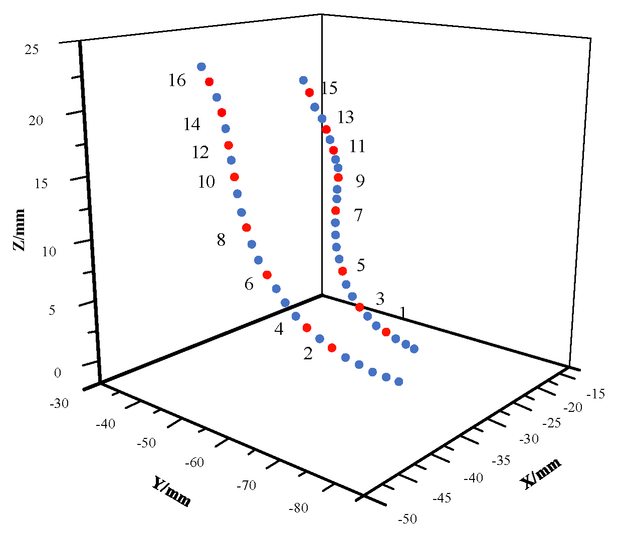
| No | Measured Value/mm | Status | No | Measured Value/mm | Status | ||||
|---|---|---|---|---|---|---|---|---|---|
| X | Y | Z | X | Y | Z | ||||
| 1 | −35.7542 | −71.4724 | 14.7275 | Pass | 9 | −45.6457 | −44.7441 | 34.2733 | Pass |
| 2 | −36.5741 | −71.2224 | 17.1114 | Failed | 10 | −42.7587 | −43.5744 | 36.7548 | Pass |
| 3 | −37.4242 | −61.0441 | 19.5853 | Pass | 11 | −42.4755 | −47.6842 | 37.3387 | Pass |
| 4 | −37.4524 | −60.2742 | 21.5781 | Failed | 12 | −41.0445 | −48.3775 | 38.3211 | Pass |
| 5 | −39.7524 | −54.4553 | 21.5334 | Pass | 13 | −38.7527 | −49.7566 | 39.5283 | Pass |
| 6 | −41.2424 | −51.7252 | 24.5745 | Pass | 14 | −40.7674 | −52.1141 | 41.3347 | Failed |
| 7 | −43.4277 | −48.5524 | 27.4228 | Pass | 15 | −36.8333 | −59.4769 | 43.2344 | Pass |
| 8 | −45.3633 | −50.4566 | 32.7527 | Failed | 16 | −38.6787 | −62.0775 | 46.3679 | Failed |
| No | Measured Value/mm | Status | No | Measured Value/mm | Status | ||||
|---|---|---|---|---|---|---|---|---|---|
| X | Y | Z | X | Y | Z | ||||
| 1 | −34.7561 | −70.0465 | 14.1042 | Pass | 9 | −43.3906 | −42.1025 | 33.4213 | Pass |
| 2 | −35.1352 | −69.0652 | 17.7841 | Pass | 10 | −45.7952 | −42.0489 | 35.0569 | Pass |
| 3 | −37.3987 | −64.1038 | 20.4408 | Failed | 11 | −44.3619 | −45.3721 | 38.1146 | Pass |
| 4 | −35.4621 | −57.1854 | 19.7619 | Pass | 12 | −43.4216 | −46.0981 | 37.4102 | Pass |
| 5 | −40.6872 | −54.3278 | 23.3561 | Failed | 13 | −37.3069 | −47.8742 | 39.3964 | Pass |
| 6 | −40.9042 | −50.6531 | 24.7848 | Pass | 14 | −37.7632 | −48.5631 | 40.9451 | Pass |
| 7 | −42.1104 | −48.7758 | 27.2246 | Pass | 15 | −35.4211 | −58.3964 | 43.0196 | Pass |
| 8 | −43.0138 | −48.6653 | 30.0193 | Pass | 16 | −36.0145 | −60.0047 | 45.8745 | Pass |
Disclaimer/Publisher’s Note: The statements, opinions and data contained in all publications are solely those of the individual author(s) and contributor(s) and not of MDPI and/or the editor(s). MDPI and/or the editor(s) disclaim responsibility for any injury to people or property resulting from any ideas, methods, instructions or products referred to in the content. |
© 2023 by the authors. Licensee MDPI, Basel, Switzerland. This article is an open access article distributed under the terms and conditions of the Creative Commons Attribution (CC BY) license (https://creativecommons.org/licenses/by/4.0/).
Share and Cite
Zhao, W.; Li, R.; Liu, X.; Ni, J.; Wang, C.; Li, C.; Zhao, L. Construction Method of Digital Twin System for Thin-Walled Workpiece Machining Error Control Based on Analysis of Machine Tool Dynamic Characteristics. Machines 2023, 11, 600. https://doi.org/10.3390/machines11060600
Zhao W, Li R, Liu X, Ni J, Wang C, Li C, Zhao L. Construction Method of Digital Twin System for Thin-Walled Workpiece Machining Error Control Based on Analysis of Machine Tool Dynamic Characteristics. Machines. 2023; 11(6):600. https://doi.org/10.3390/machines11060600
Chicago/Turabian StyleZhao, Wenkai, Rongyi Li, Xianli Liu, Jun Ni, Chao Wang, Canlun Li, and Libo Zhao. 2023. "Construction Method of Digital Twin System for Thin-Walled Workpiece Machining Error Control Based on Analysis of Machine Tool Dynamic Characteristics" Machines 11, no. 6: 600. https://doi.org/10.3390/machines11060600