Article

Towards the Design of a User-Friendly Chimney-Cleaning Robot

Department of Mechanical, Energy and Management Engineering, University of Calabria, 87036 Rende, Italy
*
Author to whom correspondence should be addressed.
Machines 2023, 11(11), 1024; https://doi.org/10.3390/machines11111024
Submission received: 31 August 2023 / Revised: 24 October 2023 / Accepted: 24 October 2023 / Published: 15 November 2023
(This article belongs to the Special Issue Mobile Robotics: Mathematics, Models and Methods)

Abstract

:
Domestic chimney cleaning is still mostly a manual procedure which can be overly complex, dangerous, and expansive. This paper describes the design of a novel robotic device for chimney cleaning that aims to provide a valuable alternative solution to the traditional manual techniques with user-friendly and low-cost features. The proposed device enables a significant reduction in operator risks, including roof falling and soot dust contact. The paper’s content describes, in detail, the design process, including a definition of the main design requirements and steps towards the manufacturing of a preliminary prototype. Moreover, a preliminary validation is described through laboratory tests to demonstrate the engineering feasibility and effectiveness of the proposed design solution for the intended semi-autonomous chimney-cleaning application.

1. Introduction

The obstruction of a chimney can arise due to the accumulation of soot and creosote, leading to stagnation and an excessive emission of smoky odors. To prevent the buildup of soot and the occurrence of fires, a proposition involves the utilization of autonomous robotic apparatus designed for chimney cleaning, such as proposed in [1,2,3,4]. Traditional methods for chimney cleaning persist, involving chimney sweeps who deploy steel or plastic brushes. Two primary manual cleaning techniques exist: the first necessitates the presence of a skilled operator employing harnesses, while the second involves cleaning the chimney from within the confines of the building. Safety considerations for the operator are paramount in both scenarios. The primary risk associated with roof-based cleaning pertains to the potential for falls. Regardless, exposure to soot dust carries the risk of cancer and soot-related asphyxiation.
Unfortunately, the specific application of robotized chimney cleaning has rarely been addressed in the literature, while there exists a wide range of investigations on robots that are capable of traversing within pipes and executing tasks related to cleaning or inspection. Several aspects of these applications are well-related to the application in this paper and several design aspects can be inspired by the need to effectively navigate and inspect pipelines, with a wide array of design solutions available in the literature. For example, the review in [5] introduces the possibility of using crawler modules, showcasing the potential for agile and adaptive movement within pipelines. Kwon et al. [6] contributed a two-module indoor pipeline inspection robot, addressing challenges related to maneuverability and control. Furthermore, autonomous navigation within pipelines has been achieved through the utilization of contact sensor modules [7], signifying advancements in reducing human intervention and enhancing inspection efficiency.
In the realm of locomotion mechanisms, the introduction of tensegrity-based inchworm-like robots [8] by Liu et al. has been revolutionary. This novel design concept imitates the principle of tensegrity, allowing for the robot to crawl through pipelines with varying diameters. A parallel-pipe-crawling pneumatic soft robot, as designed by Zhang et al. [9], highlights the versatility of soft robotics in pipeline environments, underscoring the importance of innovative design and modeling in achieving adaptable locomotion as also reported in [10,11]. The landscape of in-pipe inspection extends beyond locomotion to encompass gripping and manipulation mechanisms. Wang and Gu’s work on bristle-based pipeline robots [12] offers effective strategies for navigating pipes with challenging geometries. Additionally, the incorporation of self-locking mechanisms in inchworm in-pipe robots [13] presents a unique solution for overcoming the complexities posed by varying pipe shapes.
In the pursuit of efficient inspection across diverse industries, novel mechanisms such as multi-axial differential gear mechanisms [14] have come to the forefront. Kim et al. introduced a pioneering mechanism for in-pipe robots, exemplifying the potential of advanced mechanisms in navigating intricate pipeline scenarios. Furthermore, recent developments have extended the capabilities of in-pipe inspection to address challenges related to confined spaces. The introduction of the “Porcospino” spined single-track mobile robot [15] signifies an expansion in the scope of in-pipe inspection, enabling access to previously unreachable regions. Gripper-based climbing robots like “KharazmBot” [16] underscore the importance of robust and reliable gripping mechanisms for a variety of surfaces, highlighting advancements in robot design and thin">ality. Beyond locomotion and gripping, the survey delves into long-distance pipeline inspection [17] and novel modularized robotic systems [18], as well as bio-inspired wall-climbing robots [19], while the Mecanum-Wheeled Hybrid Hexapod [20] highlights dynamic mobility. Multiple other examples highlight the integration of mechanical design and simulation principles and cutting-edge concepts like magnetic harmonic drives to further expand the spectrum of robotic solutions, as reported, for example, in [21,22,23].
Given the above literature overview, this paper addresses the practical requirements for domestic chimney cleaning. The first phase of the design process involved formulating the design requirements and constraints. On this matter, one should note that several aspects were defined by referring to the related literature and considering the available quantitative data that were taken by referring to competitors’ designs. For example, taking into consideration the key aspects of manual operation and comparing them with comparable items on the market, the thin">al requirements of the product were established. In particular, it was established that the ideal maximum operating speed can be set at 0.15 m/s. With this speed, the robot can advance inside the pipe so that the brush can effectively remove even the most stubborn encrustations. Similarly, bearing in mind the average weight of existing built-in robots, a maximum weight of 2.5 kg was defined. In addition, the robot must meet the competitor’s standard radial size of 200 to 250 mm or a 400 to 500 mm diametral size to fit within standard chimneys. Furthermore, the total range of the robot must allow for the navigation of at least 50 m in the chimney, as also mentioned in [1,2,3,4].
This paper is organized as follows: Section 2 provides a description of the main design features of the proposed chimney-cleaning robot, as based on the main requirements that have been previously briefly outlined; Section 3 describes the process towards the manufacturing of a proof-of-concept prototype; Section 4 describes the main hardware features with calculations of the main properties; Section 5 describes the prototype testing; and Section 6 drives some conclusions and future work. It is worth mentioning that the proposed design has been submitted for patenting.

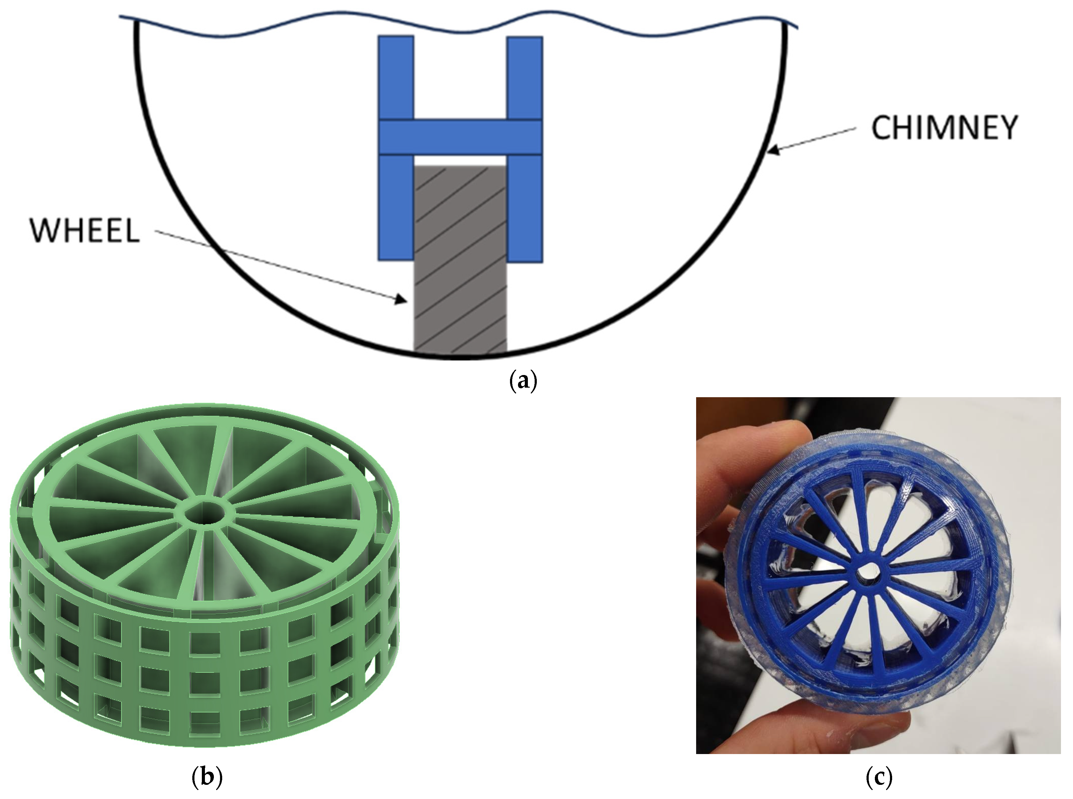
2. Chimney Cleaning Design
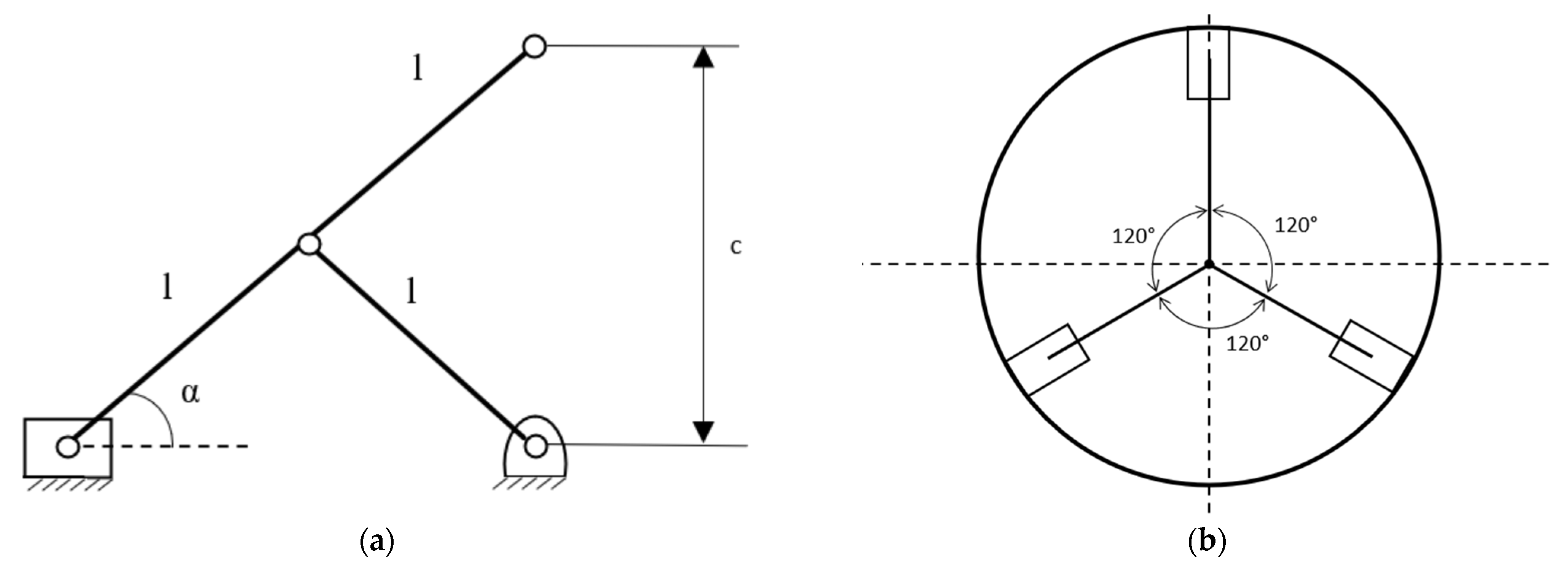
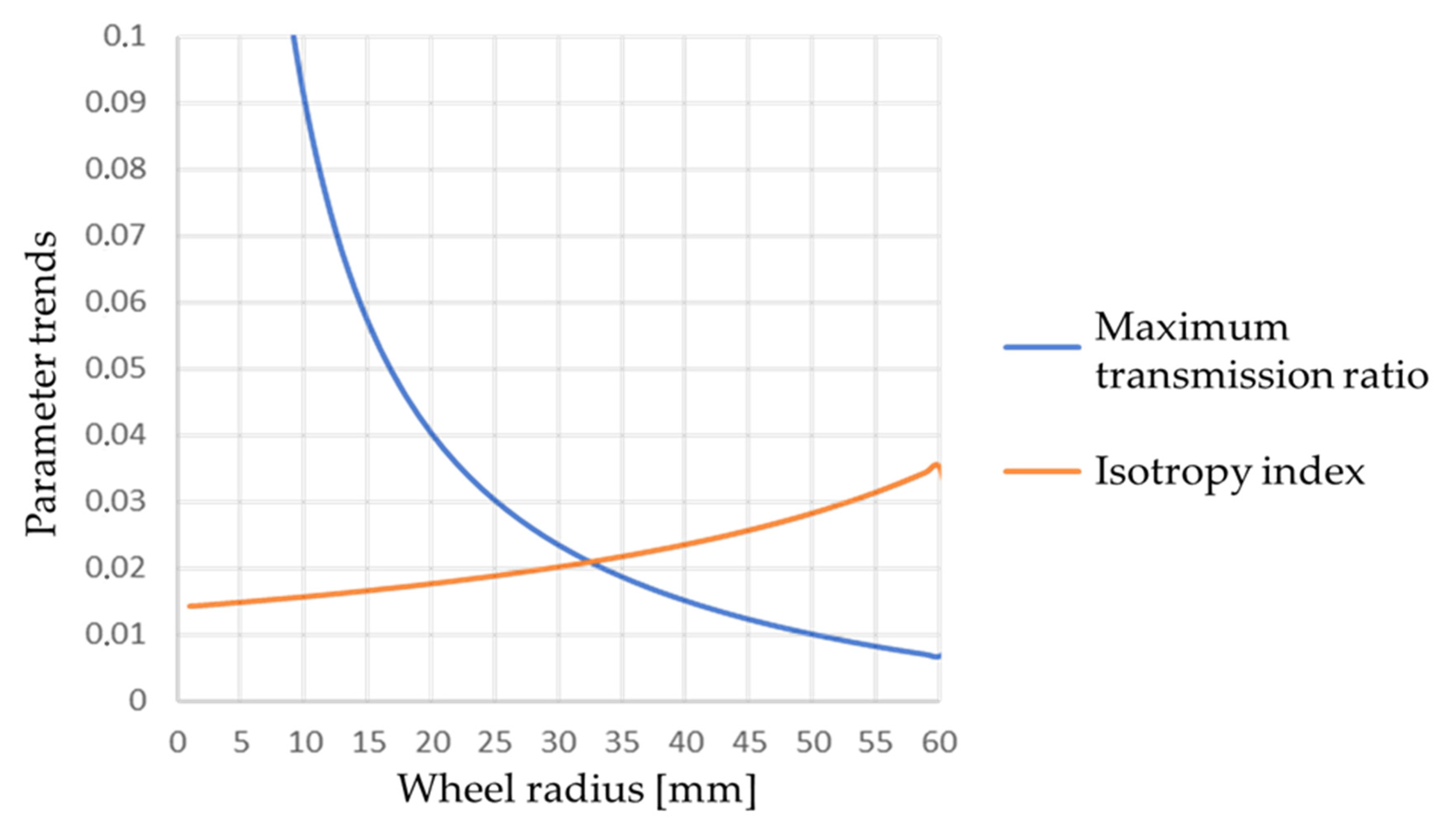
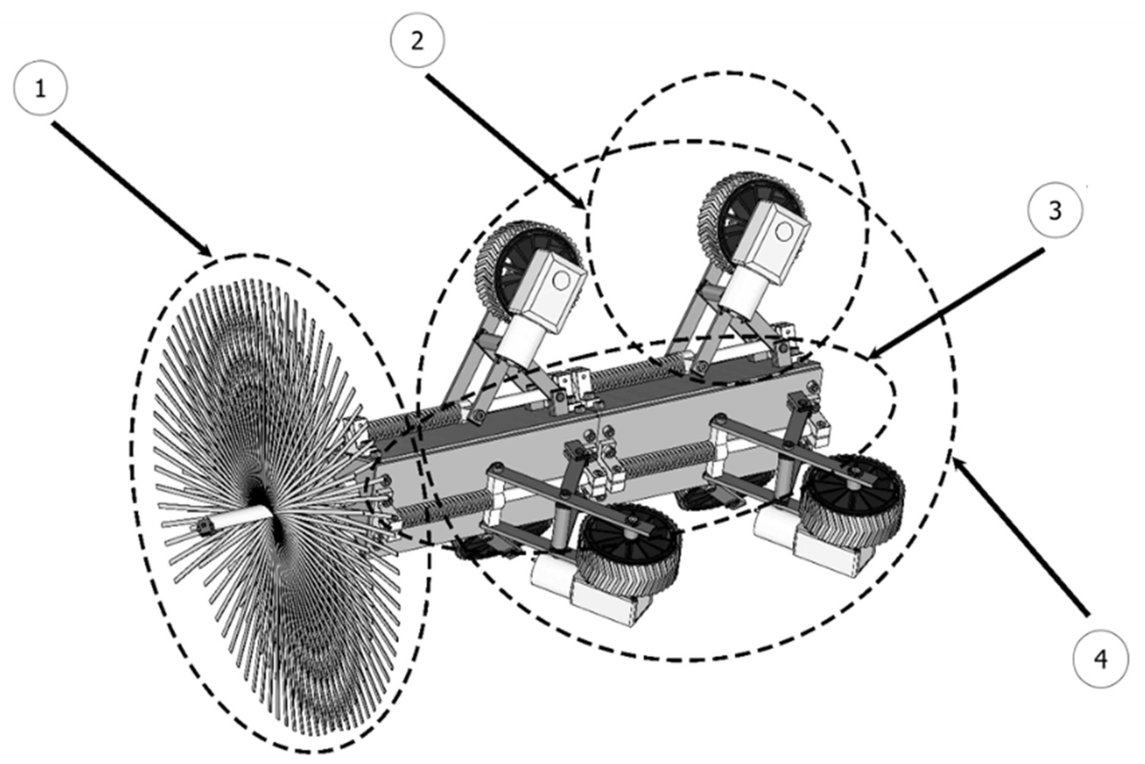
The first design step consisted of a careful literature and market review, resulting in the definition of the main design requirements and constraints that are summarized in the product design specifications that are summarized in Table 1, with an indication of the requirements that are mandatory or desirable (not mandatory). Most dimensions are identified as referring to the dimensions of standard domestic chimneys, as well as by considering the characteristics of competitor products. In particular, the robot’s cross-body dimension was defined by considering the standard 400 to 500 mm diametral size of a chimney and allowing for a minimum of 100 mm for a retractable mechanism to adapt to chimneys of various sizes, as well as for adapting to soot and asperities that can be present in the chimney. The requirements for mass, speed, and life cycle were deducted by a comparison with other similar commercial products, as well as by referring to the expectations of a standard user. The maximum robot motion refers to the maximum feasible length of a domestic chimney, equaling 50 m. It is worth noting that the proposed device has to comply with regulatory safety requirements, especially to avoid the risk of humans getting into contact with the soot. From this viewpoint, it is worth highlighting that the robot is designed to be operated remotely, providing a significant reduction in soot contact and the related risks for a human operator.
Given the variability in the pipe diameters in which the device must operate, a spring expansion system was chosen to ensure pipe–wheel contact in different configurations. In particular, the expansion mechanism can be of two types: active or passive. Active linkage systems use actuators to actively control the normal force on the contacting parts, but are bulkier and more expensive than passive systems. Passive systems, on the other hand, allow for a high adaptability to different pipe diameters using simple structures. Therefore, a passive system was chosen for this specific application.

Robotic Structure

This section discusses the design of the primary structure of the proposed robot, which allows the robot to adapt and push its wheels against the inner surface of a chimney. The robot consists of three legs with a slider-crank spring expansion mechanism design (Figure 1a) to ensure pipe–wheel contact. To ensure the stability of the robot body, a configuration was used in which the three legs are connected to the robot body and oriented at 120°, as shown in Figure 1b.
Figure 2 highlights the separation of the mechanism into free bodies by replacing the constraints with reaction forces. Namely, the mechanism on the left side is converted int the free body (1) consists of the link from D to B and the free body (2) consists of the link from A to C with addition of all the equivalent reaction forces in replacement of each constraint that has been removed. One wants to correlate the minimum contact force to be ensured ( F C ) with the spring force ( F m ) so that the main components can be designed as referring to the free body diagrams that are shown in Figure 2. For this purpose, we use the principle of virtual works (PVW) method. Specifically, when analyzing the constraint conditions, the only forces acting are F m and F C (these forces are that applied by the operator to compress the mechanism during positioning, or that exerted by the pipe wall during operation). The PVW can be written as follows:
δ W =   F m   δ x F C   δ z = 0  
where δx and δz represent the virtual displacements in the x and z directions, respectively. In addition, geometrical considerations show that:
x = 2   l   cos α  
z = 2   l   sen α  
Substituting Equations (2) and (3) into Equation (1), we obtain:
δ W = 2   l   sen α   F m   δ α 2   l   cos α   F C   δ α = 0  
From Equation (1), one can obtain:
F C = tan α F m  
The mechanism has two singularity positions with respect to the angles of 0° and 90°, so, to be on the safe side, the working range is assumed to be between the angles of 30° and 60°. To reduce the mass of the device, aluminum profiles were selected. Considering one of the wheels of the robot in contact with the pipe, in the static condition, the force distribution can be modeled as shown in Figure 3. Considering the acting forces, the following equilibrium equations can be calculated as referring to the driving wheels as:
N = F C μ   N = m   g 6 + F S   g 6 m   g 6 + F S   g 6   r = τ  
Considering our specific case, from the third equation in Equation (6), one can calculate the minimum value of the torque, which allows for the equilibrium condition of the system to be obtained as being about 0.25 Nm. This information will be needed for selecting the proper motor for the wheels.
Figure 4 shows a schematic of the proposed thin">al structure of the robot with folding arms, based on a rod-crank mechanism. A preliminary illustration of the spring mechanism that holds the wheel to the chimney wall is shown in the proposed diagram. This scheme was used to perform the dimensional synthesis of the primary components and to estimate the action and reaction forces as follows:
F m 1 = k   Δ x 1 = 20.97   N F m 2 = k   Δ x 2 = k   Δ x 1 + 2   l   cos α 2 cos   α 1 = 30.23   N
From the system of Equation (7), it is possible to obtain the values of the lumped spring stiffness k and compliant displacement Δx1 of the spring number 1, which give exactly the desired values of the elastic force, 0.73 N/mm and 28.69 mm, respectively. Given the value of Δx1 one can calculate similarly the value of the compliant displacement Δx2 of the spring 2 as equal to 41.36 mm. Considering thin beams, shear deformations are not considered, and the cross-section of the connection is given by a rectangular aluminum profile. The middle section of the connection, which contains a 4 mm hole at point D, is the most stressed. A rotary joint must be accommodated in this hole. This leads to the adoption of a 3 mm × 10 mm by 1 mm cross-section and a structural study. As explained in [23], the hole results in a stress concentration with a compression coefficient of 2.25 and a unit bending coefficient. The following conditions are imposed and checked using a factor of safety (FOS) of 2, and:
σ t = K t c + σ M S y FOS σ c = K t c σ M S y FOS
σ N = F m   cos   α   A
σ M = F m   L   sin   α   I h 2
where σt is the tensile stress, σc is the compression stress, K t c is the compression tension concentration factor, σM is the bending moment tension, σN is the normal stress tension, Sy is the yield stress, Fm is the spring force, α is the mechanism angle, I is the moment of inertia, A is the link cross-section, L is the link length, and h is the distance between the end of the robot body and the axis of the cylindrical guide. To dimension the connections correctly, it is therefore necessary to specify the range of pipe diameters in which the robot can be used, as well as to dimension the diameter of the wheel to be used. According to the design specifications, the device can be used in pipes with a diameter range between 250 mm and 300 mm. Following the minimum–maximum principle [23], the criteria used for choosing the wheel diameter are to:
  • maximize the transmission force;
  • ensure isotropy of movement in the three directions.
The optimum wheel radius, for a pipe diameter of 250 mm, is obtained from the intersection of the two curves, as shown in Figure 5.
The complete prototype consists of a frame structure, four servomotors, a wire brush, and three drive mechanisms with one spring each. Sensors and control hardware complete the robot. Figure 6 shows a diagram of the main parts of the robot body. The cross-section of the primary body is triangular. The primary body of the robot contains the controller and battery. A guide mechanism (retractable crank) is attached to each flat surface. This allows for a spring to be used to adjust and push a wheel against the inner surface of the stack. The front of the robot is equipped with a static wire brush.
Three-dimensional CAD models of the full robot are developed, as based on the scheme in Figure 6. In particular, Figure 7a shows a 3D CAD model of the leg structure as the main component of the proposed design. Figure 7b shows a 3D CAD model of the attachment of the wheel motor to the leg structure, where careful attention has been taken to avoid any interference with the pipe or any robot part.

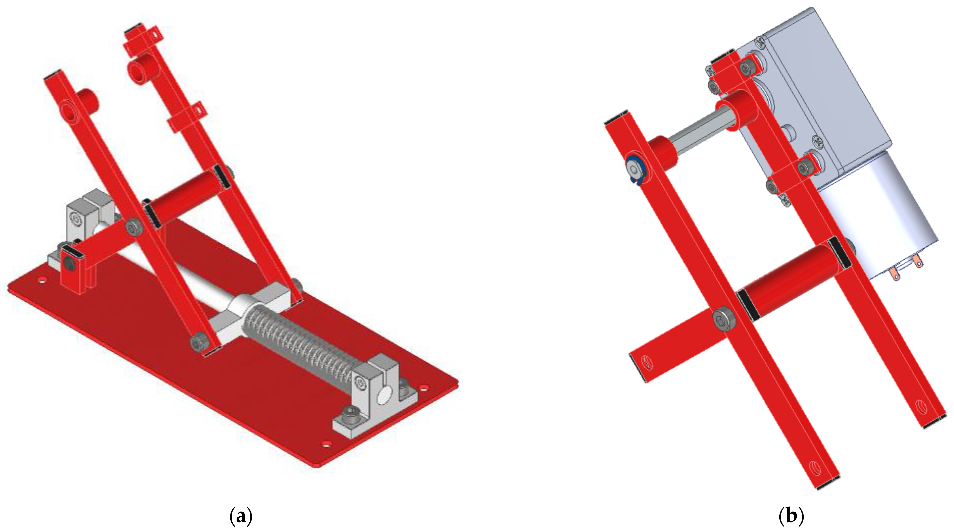
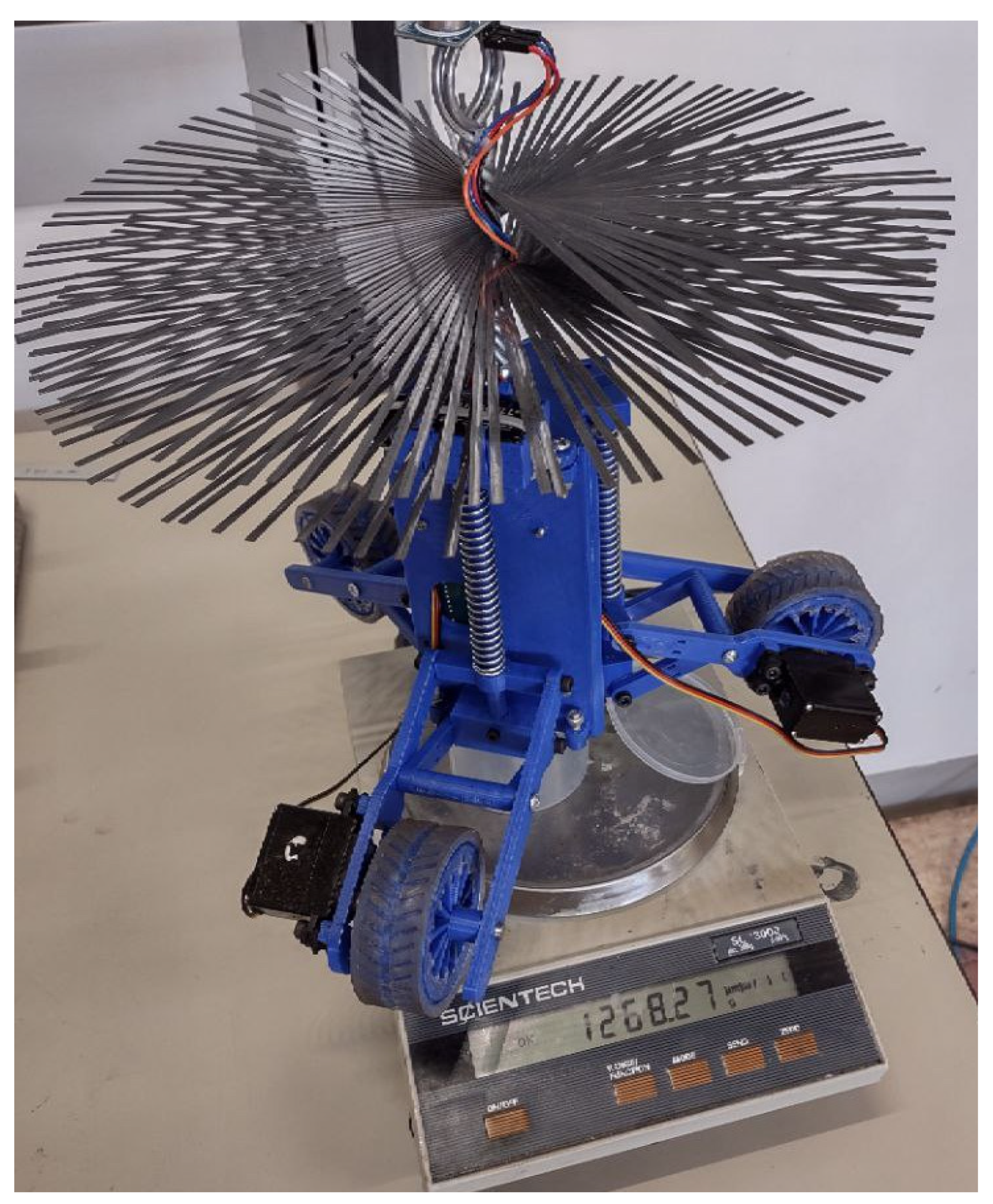
3. Prototype of the Robot

The robot’s physical prototype was created using 3D printing, with the exception of its motors, connecting parts and the brush, which are off the shelf components.

Wheels Manufacturing

We decided to create the wheels in search of a substance that would provide superior adhesion and friction on the chimney wall. After a careful review of the scientific literature, it emerged that silicone is the material most frequently used in situations involving the development of a robot inside a vertical pipe. A closed-mold casting procedure was used to create the silicone wheels (Figure 8). The wheel rim was molded in plastic and has a unique shape. A single mesh was molded on the outer wall of the rim so that the cast silicone could be mechanically attached more securely to the rim.
Several tests were conducted during the production of the wheels, resulting in a last version that was superior to the drawbacks of previous versions:
  • Wheel rim: it was decided to make the spokes thinner to lighten the wheel, to make the rim smaller to increase the thickness of the silicone, and to make the “mesh” configuration less dense;
  • Molded mold: it was produced in two separate halves. In addition, the depth of the grooves was increased to improve the grip of the wheel;
  • Bottom mold: the centering pin was removed and a circular guide was inserted to center the edge and prevent the silicone from flowing to the bottom of the mold;
  • To create an exactly symmetrical mold, the upper mold is identical to the lower mold.
Figure 9a shows the main 3D printed components and Figure 9b shows the fully assembled device at the University of Calabria.

4. Main Hardware Features

The control hardware is based on a commercial Arduino with a motor shield that has been customized. Each brushed DC motor’s battery pack absorption was calculated to be 1.2 A. A working period of 6 min was anticipated to cover a distance of 50 m at a speed of 0.15 m/s, and a 9.6 V and 2 Ah BAKTH rechargeable commercial battery was utilized. A static and dynamic analysis was used to choose Hi-Tech D485HW servomotors. The servomotors were modified to rotate continuously. Servo motor modifications included the removal of the mechanical block that restricts the rotation of the output shaft and the replacement of the potentiometer with resistors that allow for the signal to be stabilized.
The maximum motor output torque requires a 7.4 V power source. Because the Arduino Mega board does not support this voltage, an external power supply is necessary. A bespoke circuit was also constructed and fabricated to include an ultrasonic sensor HC-SR05 for detecting obstructions that could hinder the robot from moving forward. We used DC brushed motors for the final product, since continuous motion is necessary, with only a planned change in direction. The device’s progress speed is specified in the technical specifications. Based on this criterion, the rotational speed of the wheel shaft can be calculated as:
ω = v r = 0.075   m / s 0.034   m = 2.21 rad s
The required mechanical power is calculated as:
P m =   τ   ω = 1.10   W
For this design, a higher electrical power motor was sought out and successfully identified as the Walfront mo48pt3v9d, which has an electrical power of Pe = 1.50 W. Figure 10 shows the size of the chosen motor. To ensure optimal performance, elements like efficiency, torque, and compatibility were also analyzed with the device’s specifications during the research process.
The following are the features of the identified motor:
  • Free speed ωfree = 4.19 rad/s;
  • Stall torque τstall = 1.42 Nm;
  • Stall current istall = 1.15 A;
  • No-load current ifree= 0.31 A;
  • Supply voltage V = 12 V;
  • Reduction ratio = 1:224.
Characteristic curves based on the available torque are developed to estimate the motor’s operating point. The following equation describes the behavior of the output angular velocity as:
ω = ω free τ stall   τ + ω free
The required mechanical power is calculated as:
P m =   τ   ω
The following is the law that describes the trend of current i that is absorbed by the motor as a thin"> of the given torque τ as:
i = i stall i free τ stall   τ + i free
at the end, the expression of efficiency is:
e = τ   ω i   V
To plot the motor’s characteristic curves as a thin"> of the torque, a code was written in the MATLAB application, which is included in the attachment. Figure 11 shows the calculated values for the speed, power, current, and efficiency as thin"> of the torque.

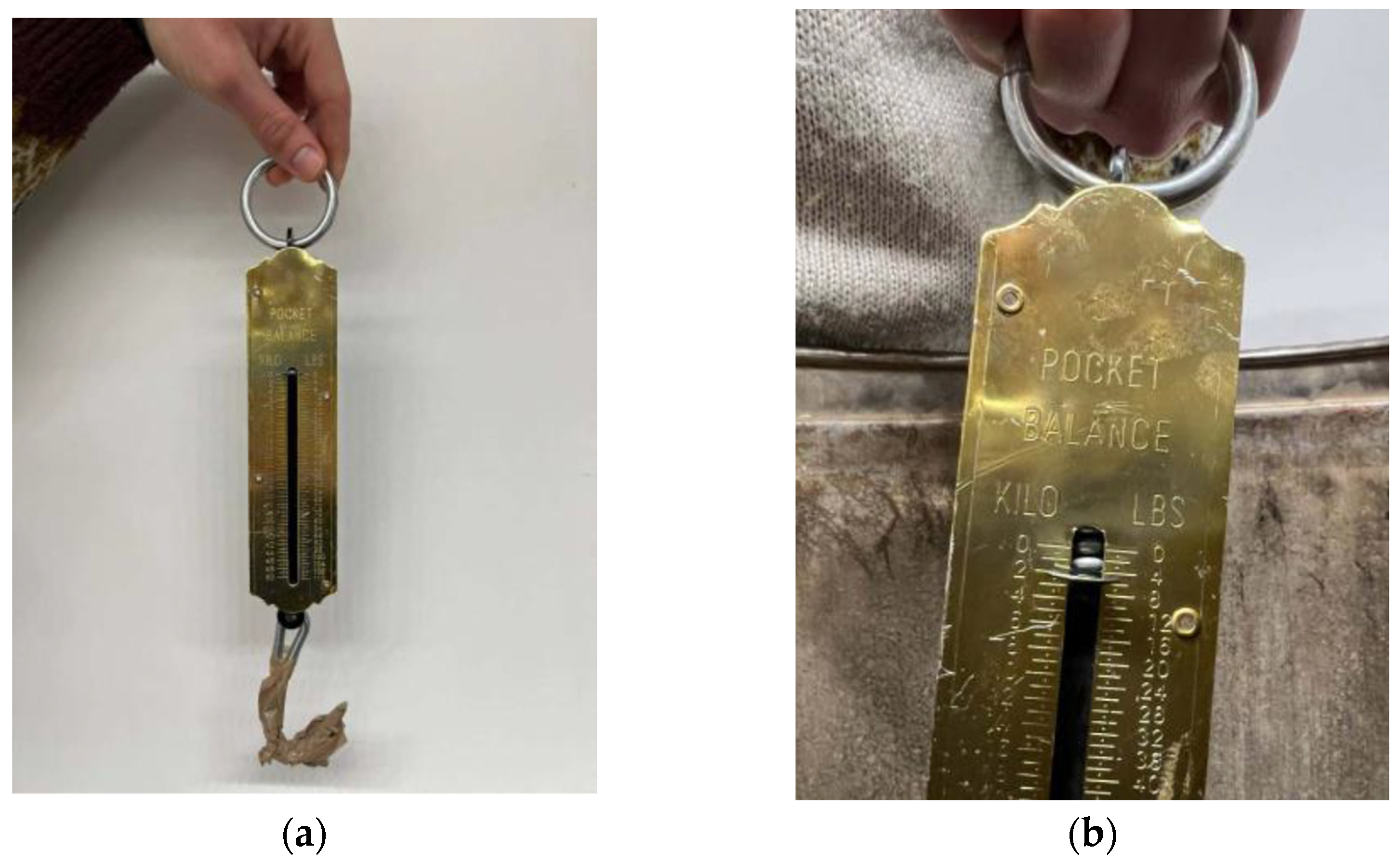
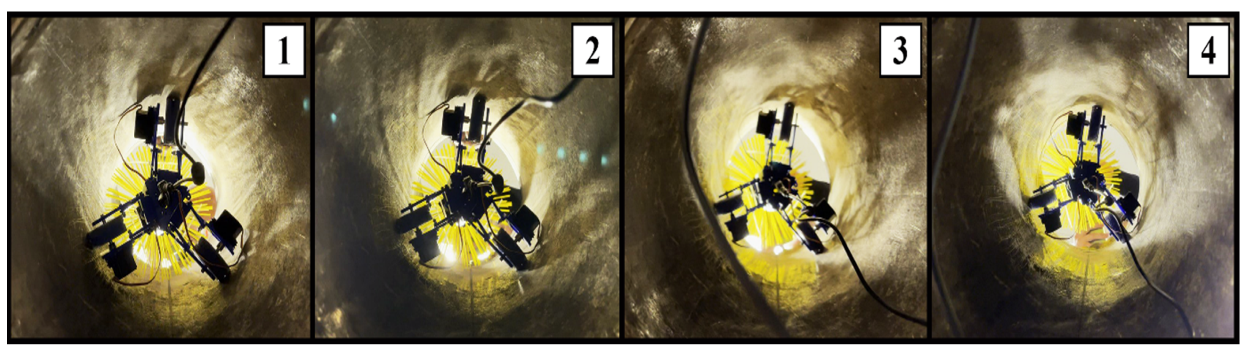
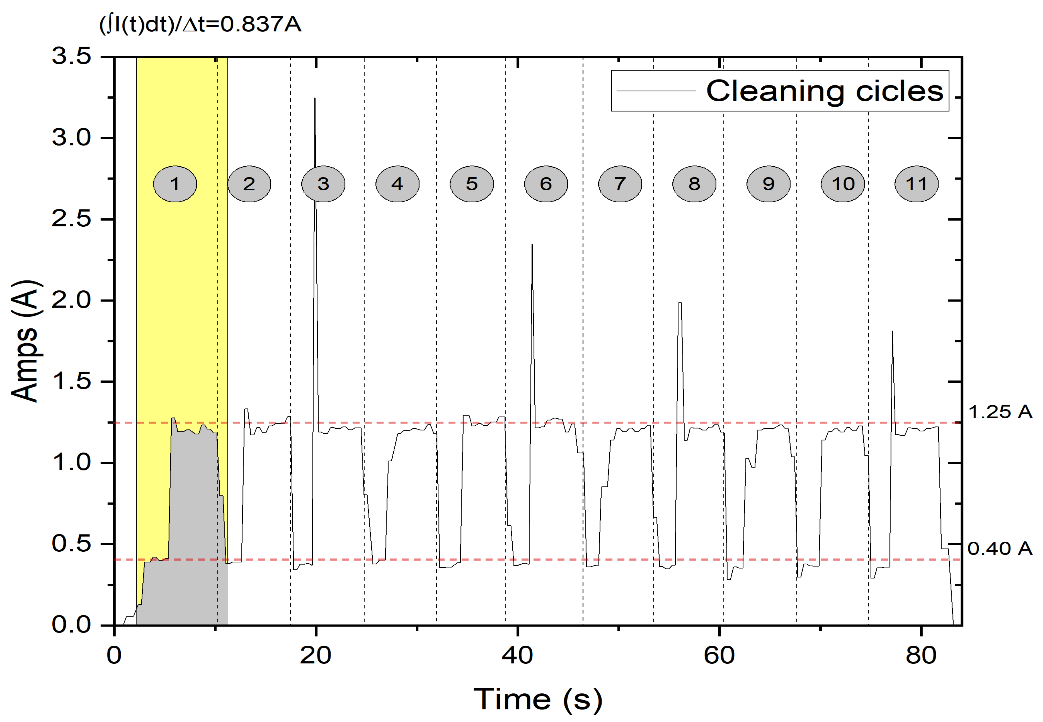
5. Preliminary Experimental Tests

A basic prototype was created and tested at the University of Calabria using two pipes with diameters of 250 mm and 300 mm, which are common flue pipe dimensions, as illustrated in Figure 12a,b. The spring mechanism allowed the device to easily adapt to the two diameters, ensuring the proper adhesion of the wheels on the chimney walls.
A dynamometer was used to measure the resistance force of the brush. This test shows that, during movement, the brush resists with a force of 1 kg (Figure 13).
The flexibility of the kinematics and the right initial configuration of the links were evaluated during the device’s insertion into the pipes (Figure 14).

Actuation Tests

The first set of tests were performed on a horizontally oriented chimney. This test specifically checked the absence of parts in contact, the adhesion of the wheels on the pipe, the performance supplied by the motors, and the device’s balance during the journey. It is worth mentioning that the static brush, as shown in Figure 10, aids in maintaining balance along the chimney axis during motion in straight pipes. However, the device is constructed to have a modular shape. The connection of multiple modules can also enable turning in the case of non-straight chimneys. However, this case has not been implemented for the built prototype.
The second series of testing was performed on a vertically positioned chimney with the device being moved upwards. The outcome of this test demonstrated that the device can perform the ascent phase, as illustrated in Figure 15. The electrical current consumption was measured during the cleaning test for several cleaning cycles (Figure 16) in order to determine the needed power and confirm the design stages. Due to the resistance of the robot’s own weight and brush friction, the robot had a maximum current consumption of 1.25 A during the ascending phase, as projected. The current consumption during the descendent phase was around 0.4 A. Calculating the integral of the current drawn in a cleaning cycle and dividing by the duration of the cycle, the average current consumption was 0.837 A.
The robot performed very well in this test, easily overcoming obstacles and successfully navigating through them again when the motion was reversed (Figure 17). This proves the feasibility of the proposed design with a remarkably simple, low-cost, and user-friendly control strategy, which are fundamental features for this specific application, where the device needs to be operated by non-expert users who mostly need basic, semi-automatic operations. It is worth noting that the addition of more sensors or a more complex control scheme would lead to a significant increase in costs that is undesirable for this specific application, where the price is of upmost significance for the market deployment of such a device. Similarly, the application does not require a fast dynamics model, since that would, again, negatively impact the costs. One should also note that, given the features of our design, a simple close loop control scheme was proposed by using the position in the pipe as the main measured feedback. Such a position control scheme does not require complex kinematics or dynamics models while it is demonstrated to be fully effective for the intended application.
The robot comes to a halt when the dynamometer registers a force equal to the weight of the robot (about 1.27 kg, as illustrated in Figure 18) plus the resistive force of the brush. This is owing to the adoption of a safety factor of 2 during the analytical motor sizing process.

6. Conclusions

This paper addressed the design of a novel robot for robot for quick and safe semi-automatic chimney cleaning. The main design steps were carefully described to achieve a low-cost and user-friendly design solution. A first prototype was manufactured and preliminary tested to validate its engineering feasibility and user friendliness in main operation conditions. The tests showed very promising features, and a patent application has been submitted. Future work will include further tests, as well as the addition of an active rotating brush and a device for collecting the eliminated soot.

Author Contributions

Conceptualization, methodology, software, validation, data curation, writing of first draft, equally distributed among all authors, writing—review and editing, and supervision, G.C. (Giuseppe Carbone). All authors have read and agreed to the published version of the manuscript.

Funding

We acknowledge partial financial support from: PNRR MUR project PE0000013-FAIR.

Data Availability Statement

All the related date have been provided within this paper.

Conflicts of Interest

The authors declare no conflict of interest.

References

  1. Campbell, R.; Home Fires Involving Heating Equipment. National Fire Protection Association Research. 2018. Available online: https://www.nfpa.org/-/media/Files/News-and-Research/Fire-statistics-and-reports/US-Fire-Problem/Fire-causes/osHeating.pdf (accessed on 23 October 2023).
  2. Marcinko, P.; Virgala, I.; Miková, Ľ.; Prada, E.; Kelemenová, T.; Kelemen, M.; Varga, M. Chimney Cleaning and Inspection Robot. Acta Mech. Slovaca 2019, 23, 6–9. [Google Scholar] [CrossRef]
  3. Alegre, T.V. Appliance to Clean Industrial Chimneys. 2004. Available online: https://patents.google.com/patent/US20040231089A1/en (accessed on 23 October 2023).
  4. Sinčák, P.J.; Virgala, I.; Kelemen, M.; Prada, E.; Bobovský, Z.; Kot, T. Chimney sweeping robot based on a pneumatic actuator. Appl. Sci. 2021, 11, 4872. [Google Scholar] [CrossRef]
  5. Kahnamouei, J.T.; Moallem, M. A comprehensive review of in-pipe robots. Ocean. Eng. 2023, 277, 114260. [Google Scholar] [CrossRef]
  6. Rusu, C.; Mihai, O.T. Adapting Mechanisms for In-Pipe Inspection Robots: A Review. Appl. Sci. 2022, 12, 6191. [Google Scholar] [CrossRef]
  7. Jang, H.; Kim, T.Y.; Lee, Y.C.; Song, Y.H.; Choi, H.R. Autonomous Navigation of In-Pipe Inspection Robot Using Contact Sensor Modules. IEEE/ASME Trans. Mechatron. 2022, 27, 4665–4674. [Google Scholar] [CrossRef]
  8. Liu, Y.; Dai, X.; Wang, Z.; Bi, Q.; Song, R.; Zhao, J.; Li, Y. A Tensegrity-Based Inchworm-Like Robot for Crawling in Pipes with Varying Diameters. IEEE Robot. Autom. Lett. 2022, 7, 11553–11560. [Google Scholar] [CrossRef]
  9. Zhang, Z.; Wang, X.; Wang, S.; Meng, D.; Liang, B. Design and Modeling of a Parallel-Pipe-Crawling Pneumatic Soft Robot. IEEE Access 2019, 7, 134301–134317. [Google Scholar] [CrossRef]
  10. Colvalkar, A.; Nagesh, P.; Sachin, S.; Patle, B.K. A Comprehensive Review on Pipe Inspection Robots. Int. J. Mech. Eng. 2021, 10, 51–66. [Google Scholar]
  11. Brown, L.; Carrasco, J.; Watson, S. Autonomous Elbow Controller for Differential Drive In-Pipe Robots. Robotics 2021, 10, 28. [Google Scholar] [CrossRef]
  12. Qiao, J.; Shang, J.; Goldenberg, A. Development of Inchworm In-Pipe Robot Based on Self-Locking Mechanism. IEEE/ASME Trans. Mechatron. 2012, 18, 799–806. [Google Scholar] [CrossRef]
  13. Kim, H.M.; Choi, Y.S.; Lee, Y.G.; Choi, H.R. Novel Mechanism for In-Pipe Robot Based on a Multiaxial Differential Gear Mechanism. IEEE/ASME Trans. Mechatron. 2017, 22, 227–235. [Google Scholar] [CrossRef]
  14. Nodehi, S.E.; Bruzzone, L.; Fanghella, P. Porcospino, spined single-track mobile robot for inspection of narrow spaces. Robotica 2023, 41, 3446–3462. [Google Scholar] [CrossRef]
  15. Boomeri, V.; Tourajizadeh, H.; Askarian, H.R.; Pourebrahim, S. Design, modeling, and manufacturing of a novel robust gripper-based climbing robot: KharazmBot. Robotica 2023, 41, 2365–2396. [Google Scholar] [CrossRef]
  16. Zhao, J.; Wang, J.; Liu, Q.; Luo, X.; Dong, X. A review of mechanical model, structure, and prospect for long-distance pipeline pig and robot. Robotica 2022, 40, 4271–4307. [Google Scholar] [CrossRef]
  17. Jang, H.; Kim, H.M.; Lee, M.S.; Song, Y.H.; Lee, Y.; Ryew, W.R.; Choi, H.R. Development of modularized in-pipe inspection robotic system: MRINSPECT VII. Robotica 2022, 40, 1361–1384. [Google Scholar] [CrossRef]
  18. Li, H.; Sun, X.; Chen, Z.; Zhang, L.; Wang, H.; Wu, X. Design of a wheeled wall climbing robot based on the performance of bio-inspired dry adhesive material. Robotica 2022, 40, 611–624. [Google Scholar] [CrossRef]
  19. Li, D.; Pan, Z.; Deng, H.; Peng, T. Trajectory tracking control law of multi-joint snake-like robot based on improved snake-like curve in flow field. Int. J. Adv. Robot. Syst. 2019, 16, 1729881419844665. [Google Scholar] [CrossRef]
  20. Orozco-Magdaleno, E.C.; Gomez-Bravo, F.; Castillo-Castaneda, E.; Carbone, G. Evaluation of Locomotion Performances for a Mecanum-Wheeled Hybrid Hexapod Robot. IEEE/ASME Trans. Mechatron. 2021, 26, 1657–1667. [Google Scholar] [CrossRef]
  21. Perez-Diaz, J.L.; Diez-Jimenez, E.; Valiente-Blanco, I.; Cristache, C.; Alvarez-Valenzuela, M.-A.; Sanchez-Garcia-Casarrubios, J.; Ferdeghini, C.; Canepa, F.; Hornig, W.; Carbone, G.; et al. Performance of magnetic-superconductor non-contact harmonic drive for cryogenic space applications. Machines 2015, 3, 138–156. [Google Scholar] [CrossRef]
  22. Salvatore, M.M.; Galloro, A.; Muzzi, L.; Pullano, G.; Odry, P.; Carbone, G. Design of PEIS: A low-cost pipe inspector robot. Robotics 2021, 10, 74. [Google Scholar] [CrossRef]
  23. Pilkey, W.D.; Pilkey, D.F. Peterson’s Stress Concentration Factors, 3rd ed.; John Wiley & Sons: Hoboken, NJ, USA, 2008. [Google Scholar]
  24. Micro Gear Reduction Motor 12V DC Worm Reversible. Available online: https://it.dhgate.com/product/micro-gear-reduction-motor-12v-dc-worm-reversible/429568192.html (accessed on 28 September 2023).
Figure 1. A schematic design of the proposed robot structure: (a) the proposed leg mechanism for ensuring adaptability of the wheel to the pipe; and (b) location of the three legs in a pipe cross section view.
Machines 11 01024 g001
Figure 2. Free body diagrams of the leg mechanism. Note that the figure highlights the separation of two free bodies. Namely, the mechanism on the left side is converted into the free body (1) that consists of the link from D to B and the free body (2) consists of the link from A to C with addition of the reaction forces.
Machines 11 01024 g002
Figure 3. Diagram of forces acting on a wheel.
Machines 11 01024 g003
Figure 4. Diagram of the structure of the spring-expansion system based on a connecting rod-crank mechanism.
Machines 11 01024 g004
Figure 5. Development of wheel radius according to design parameters.
Machines 11 01024 g005
Figure 6. The schematic of the proposed robot with its main components; numbers in the image correspond to 1—metal brush; 2—wheels; 3—links with spring; 4—robot body.
Machines 11 01024 g006
Figure 7. Three-dimensional CAD models for the proposed design solution: (a) a detail of the leg design; and (b) attachment of the wheel motor to the leg structure.
Machines 11 01024 g007
Figure 8. Schemes for the wheel: (a) a scheme of the wheel in contact with the pipe; (b) 3D CAD model of a wheel; and (c) a built wheel prototype with shape adapted to the pipe radius.
Machines 11 01024 g008
Figure 9. Built device at University of Calabria: (a) 3D printed components and (b) assembled device.
Machines 11 01024 g009
Figure 10. Walfront motor dimensions (image modified from a publicly available source at [24]).
Machines 11 01024 g010
Figure 11. Characteristic motor curves and working condition (the marked point on the plots refers to the ideal operation conditions for the selected motor).
Machines 11 01024 g011
Figure 12. Tests in (a) pipe of 240 mm diameter and (b) 300 mm diameter.
Machines 11 01024 g012
Figure 13. (a) Dynamometer used for the tests and (b) measured value.
Machines 11 01024 g013
Figure 14. Sequence for inserting device in the chimney: 1—manually approaching the chimney; 2—incipient insertion of the robot into the chimney; 3—completed insertion of the robot.
Machines 11 01024 g014
Figure 15. Frame sequence of descendent and ascendant phases during a cleaning cycle: 1—robot starting the descent towards the base of the chimney; 2—robot progressing towards the base; 3—robot reaching the base; 4—robot starting the ascent phase to reach the chimney exit.
Machines 11 01024 g015
Figure 16. Acquisition of the current consumption during the actuation cycles (numbers from 1 to 11 identify each of the 11 cleaning cycles that have been performed during the experimental test. Each cleaning cycle consists of ascending and descending the full length of the chimney.
Machines 11 01024 g016
Figure 17. Robot’s link movements during obstacle avoidance (numbers identify the phases of obstacle avoidance; namely, in phase 1 the wheel approaches an obstacle; in phase 2 the robot leg adshortens its size to overcome the obstacle; in phase 3 the robot leg returns to its original length after overcoming the obstacle).
Machines 11 01024 g017
Figure 18. Measurement of the prototype weight.
Machines 11 01024 g018
Table 1. Definition of the main product design specifications (PDS).
PRODUCT DESIGN SPECIFICATIONS
FUNCTIONCHIMNEY CLEANING DEVICE
PERFORMANCE AND SIZEDIMENSIONS AND MASS OF THE DEVICE
BODY CROSS DYMENSION:
300–400 mm (mandatory)
  • diametral expansion: must be less than the diameter of the smallest pipe
  • the dimensions must allow the device to fit comfortably into a chimney
MASS: ≤ 2.2 KG (desired)
  • avoid damaging the chimney
  • cost reduction
BRUSH SIZE AND MASS
DIAMETER: same of chimney (mandatory)
  • various diameter for off-the-shelf brushes
  • available length for off-the-shelf brushes
  • Avoid overload
LENGTH: no specific requirement
MASS: ≤ 0.3 KG (desired)
MOTION
SPEED: ≤ 0.15 M/S (desired)
MOTION LENGTH: up to 50 m
  • analyzing similar applications [9,10]
  • standard domestic chimneys can exceptionally reach this maximum length
POSITIONING
POSITIONING AT CHIMNEY: Manual
  • For safety purposes and for cost reduction, manual placement in at the outer of the chimney
EXECUTION
OPERATION: automatic or semi-automatic
  • Preferred automatic operation along the chimney
COMPATIBILITY
Adaptability to various chimneys
  • Operate in different diameter’s pipes
MAINTENANCE
At Each Use: Cleaning Brush and Robot Body
  • soot removed from the chimney can be partially deposited on the brush, and on the wheels
Periodic: Wheel Cleaning Every Two-Three Uses
Extraordinary: Replacement of Wheels, Brush, and Motors (desired)
  • Given the specific harsh environment, it can be necessary to replace some components
LIFE IN SERVICE
1000 h (desired)
  • Common operation time of motors [11].
MANUFACTUREPRODUCTION COST
≤ €250 (desired)
  • Considering competitors and market searches
TERMS OF USEOPERATING TEMPERATURE
0–50 °C (mandatory)
  • Standard operation range for similar devices
PRESENCE OF EXTERNAL AGENTS
Soot
  • Typical operation condition for this device
MATERIALDEVICE BODY
Aluminum and plastic (desired)
  • aluminum for thin and profiled structures, plastic for covers as typical for similar devices
BRUSH
Off-the-shelf brush (desired)
  • polyethylene brush for steel pipes
  • steel brush for other pipes
Disclaimer/Publisher’s Note: The statements, opinions and data contained in all publications are solely those of the individual author(s) and contributor(s) and not of MDPI and/or the editor(s). MDPI and/or the editor(s) disclaim responsibility for any injury to people or property resulting from any ideas, methods, instructions or products referred to in the content.

