
Buckling of Coated Functionally Graded Spherical Nanoshells Rested on Orthotropic Elastic Medium

1
Mining Engineering Department, King Abdulaziz University, Jeddah P.O. Box 80204, Saudi Arabia
2
Department of Technology, University Centre of Naama, Naama 45000, Algeria
3
Laboratoire d’Etude des Structures et de Mécanique des Matériaux, Département de Génie Civil, Faculté desSciences et de la Technologie, Université Mustapha Stambouli, Mascara 29000, Algeria
4
Faculty of Engineering, Mechanical Engineering Department, King Abdulaziz University, Jeddah P.O. Box 80204, Saudi Arabia
*
Author to whom correspondence should be addressed.
Mathematics 2023, 11(2), 409; https://doi.org/10.3390/math11020409
Submission received: 7 November 2022
/
Revised: 3 January 2023
/
Accepted: 10 January 2023
/
Published: 12 January 2023
(This article belongs to the Section Engineering Mathematics)
Abstract
:Coated functionally graded materials (FGMs) are used in several industrial structures such as turbine blades, cutting tools, and aircraft engines. Given the need for analytical and numerical analysis of these complex structures, a mathematical model of tricoated FG structures is presented for the first time in this paper. The objective of this work was to analyze analytically the buckling problem of unidirectional (1D), bidirectional (2D), and tridirectional (3D) coated FG spherical nanoshells resting on an orthotropic elastic foundation subjected to biaxial loads. Based on the generalized field of displacement, a 2D higher-order shear deformation theory was proposed by reducing the number of displacement variables from five to four variables for specific geometry cases. The nonlocal strain gradient theory was employed to capture the size-dependent and microstructure effects. The equilibrium equations were performed by applying the principle of the virtual work, and the obtained differential equations were solved by applying the Galerkin technique to cover all possible boundary conditions. The proposed elastic foundation was defined based on three parameters: one spring constant and two shear parameters referring to the orthotropy directions. A detailed parametric analysis was carried out to highlight the impact of various schemes of coated FGMs, gradient material distribution, length scale parameter (nonlocal), material scale parameter (gradient), geometry of the nanoshell, and variation in the orthotropic elastic foundation on the critical buckling loads.
Keywords:
coated functionally graded shell; biaxial loads; spherical nanoshells; four-variable HSDT; nonlocal strain gradient theoryMSC:
74E301. Introduction
Among the fundamental engineering structures, shells have numerous applications in many fields such as aerospace, automobile, pressure vessel, marine ship, turbomachinery, etc. [1]. A spherical shell is a doubly curved shell with constant curvature in the meridional and circumferential directions and two radii of equal curvature [2]. A functionally graded material (FGM) is an advanced composite of ceramic/metal constituents with a continuous gradation through spatial directions according to the design specifications and operational conditions [3]. As the dimensions of a structure approach the size of its material microstructure, size effects that are ignored by classical continuum are observed. Hence, to envision the mechanical responses of structures down to the nano size accurately, advanced and modified continuum theories have been applied [4,5]. Nguyen et al. [6] improved the load-carrying capacity and strength of membrane structures by exploiting the advantages of an FG carbon-nanotube-reinforced composite (CNTRC) material.
Ansari et al. [7] presented Mindlin’s strain gradient theory to consider the size-dependent effect on the vibration and instability of conveying fluid FG nanoshells under thermo-mechanical loads. Kar and Panda [8] studied the nonlinear thermomechanical deformation behavior of an FG shallow spherical shell panel using Voigt’s micromechanical rule. Fattahi and Sahmani [9] illustrated the size-dependent impact on the nonlinear instability response of FG-CNTRC nanoshells with temperature-dependent material properties under hydrostatic pressure and heat conduction. Faleh et al. [10] studied the forced vibration of a porous FG nonlocal strain gradient theory nanoshell rested on an elastic foundation and exposed to a transverse partial dynamic load with a specific frequency of excitation. Barati [11] examined the vibration response of even and uneven porous FG nanoshells in the frame of nonlocal strain gradient elasticity. Sahmani and Aghdam [12] analyzed the axial buckling and postbuckling response of cylindrical FG nanoshells in the presence of surface free-energy effects by using a perturbation technique. Blooriyan et al. [13] developed an analytical solution to explore the pre/postbuckling responses of circular cylindrical nanoscale shells under thermomechanical loads in the framework of Gurtin–Murdoch surface elasticity theory. Karami et al. [14] studied the elastic bulk wave characteristics of prestressed FG anisotropic bi-Helmholtz nonlocal strain gradient nanoshells in a magnetic field. Lu et al. [15] explored analytically the vibration response of FG cylindrical nonlocal strain gradient nanoshells that incorporated surface effects using first-order shear deformation theory. Safarpour et al. [16] investigated the size-dependent effect on the thermal buckling and free and forced vibration of an FG multilayer composite cylindrical shell resting on an elastic foundation. Sahmani et al. [17] developed a surface elastic shell model by incorporating modal interactions to study the nonlinear primary resonance of nanoshells by using a multiple-timescale technique. Forsat et al. [18] studied the transient vibrational response of a porous FG cylindrical nonlocal strain gradient nanoshell under different impulsive loadings by using an inverse Laplace transform technique.
Karami and Shahsavari [19] studied the forced resonant vibration response of graphene-nanoplatelet-reinforced FG polymer composite doubly curved nonlocal strain gradient theory nanoshells. Karami and Janghorban [20] studied analytically the static bending and buckling of a quasi-3D FG doubly curved nonlocal and strain gradient nanoshell. Li et al. [21] illustrated analytically the surface stress influence on the nonlinear free vibrations of FG nanoshells in the presence of modal interaction via the Galerkin technique. Dindarloo and Zenkour [22] applied nonlocal strain gradient theory to present the size-dependent effect on the bending response of FG spherical nanoshells exposed to a thermal environment. Arefi and Talkhunche [23] studied the vibration responses of an FG cylindrical nanoshell using the higher-order shear deformation theory. Cao et al. [24] considered analytically the free vibration of 3D FG nonlocal nanoplates and nanoshells by using the Galerkin solution method. Heidari et al. [25] presented the impact of distributed piezoelectric segments on static critical buckling of an FG cylindrical micro/nanoshell based on Navier’s technique. Zou and Dindarloo [26] studied the static response of FG cylindrical nonlocal elastic nanoshells in a thermal environment by using the Galerkin solution method. Arefi et al. [27] used nonlocal elasticity theory and two-variable sinusoidal shear deformation theory to investigate the bending response of FG composite doubly curved nanoshells with thickness stretching. Daikh et al. [28] developed a comprehensive study of the static deflection and buckling stability of axially FG carbon-nanotube-reinforced composite (FG-CNTRC) plates with temperature-dependent material properties. Ghandourah et al. [29] studied the bending and buckling of FG-CNTRC laminated hyperbolic higher-order shear deformation plates by using quasi-3D nonlocal strain gradient theory. Shi et al. [30] examined the statics and dynamics of an electro-thermomechanically porous FG modified couple-stress nanoshell conveying a fluid flow under a temperature gradient and a uniform electrical field. Melaibari et al. [31] examined analytically the dynamic behavior of randomly oriented FG-CNTRC laminated shells with different geometries. Yang et al. [32] investigated the static and dynamic stability analyses of an FG-CRNC cylindrical shell subjected to a non-normal boundary condition with one generatrix clamped.
The above review demonstrated that the studying of buckling response of coated FG spherical nanoshells rested on an orthotropic elastic medium has not been considered before. Therefore, this study considered the modeling, simulation, and investigation of buckling response for this problem. The rest of the article is organized as following: Section 2 presents the geometrical modeling and material distribution function. Basic equations of the kinematics/displacement field, constitutive equations, modified continuum theory, and equilibrium equations are developed in Section 3. The analytical solution is presented in Section 4 and Appendix A. The numerical results used to investigate the effects of the material distribution, geometrical parameters, nanoscale and microstructure scale, and elastic foundations on the buckling response are discussed in Section 5. The conclusions and main points are summarized in Section 6.
2. Geometrical Modeling and Material Distribution Functions
We constructed a model of an FG shell in the spherical coordinate system (x, y, z) of thickness h and width a × b as shown in Figure 1. The principal radii of curvature of the mid-plane was Rx in the x direction and Ry in the y direction. The shell was composed of metal, and the ceramic and material properties were graded continuously from the edges to the core. Two types of ceramic/metal distribution are presented in this study: hard core (HC) (for ceramics core) and soft core (SC) (for metal core) FGMs. Each FGM type had five schemes (FG-A, FG-B, FG-C, FG-D, and FG-E) as shown in Figure 2 and Figure 3. The effective mechanical properties could be portrayed by the law of mixture as [33]:
where and are the corresponding mechanical properties of the metal and the ceramic, respectively; these were related to the temperature of the environment. The volume fraction of the ceramic phase in the x, y, and z directions can be expressed as:
where , , and are the inhomogeneity indexes in the x, y, and z directions respectively. For the HC-coated functionally graded shell, the total volume fraction can be given as:
and for the SC-coated FG shell as:
3. Basic Equations
3.1. Generalized Higher-Order Shear Deformation Theory
The displacement field is based on the classical generalized higher-order shear deformation theory (HSDT), which contains five displacements variables that can be given by [4]:
where , , and are the displacement components along the x, y, and z directions, respectively; and and are the rotations of the transverse normal around the x and y axes, respectively. presents a shape function that defines the variation in the shear distribution along the composite shell thickness:
3.2. Four-Variable Higher-Order Shear Deformation Theory
For special cases in which the rotations and in the x and y directions are the same, a new field of displacement was proposed by integrating these rotations into one “”. The assumption of the proposed field of displacement is given as follows:
- The thickness h of the FG shell is uniform.
- The material properties of the FG shell are symmetric with respect to the midplane (x, y, 0).
- The opposite boundary conditions must be the same (e.g., SSSS, CCCC, and CCSS).
Taking into account the above assumptions, the number of the unknowns of the displacement field is reduced from five to four unknowns as:
The normal and shear strains at any generic point through the domain of the shell can be stated as:
where is the slope of transverse displacement . By taking into consideration the small-scale effect, the nonlocal strain gradient constitutive stress–strain relations are expressed by:
where is the Laplacian operator , , and , in which and capture the nonlocal effects and the strain gradient effects, respectively. The material constants are expressed as [14]:
where and are Young’s modulus and Poisson’s coefficient, respectively. To obtain the equilibrium equations of the coated FG nanoshell, the variational principle was employed. By considering the action of both the biaxial loadings and the elastic foundation, the strain energy of the coated FG nanoshell can be determined as:
where , , and denote the force, the moment resultants, and the additional moment resultants, respectively; and and are the axial applied mechanical loadings in the x-direction and y-direction, respectively.
The proposed elastic foundation was defined based on three parameters (one spring constant and two shear parameters) that referred to the orthotropy directions as an extension of Pasternak model [34]:
where is the modulus of the subgrade reaction (elastic coefficient of Winkler foundation); and correspond to the shear foundation parameters in the and directions, respectively; and represents the orthotropy direction.
The force and moment resultants could be portrayed as:
Then, the equilibrium equations of the coated FG-shell based were derived as follows:
By inserting the stress/strain relations into the force and moment resultants given in Equation (15), the equilibrium equations of the coated FG shells can be transformed as follows:
The stiffnesses coefficients can be expressed as:
4. Analytical Solution
Based on the proposed four-variable HSDT in conjunction with nonlocal strain gradient theory, an analytical solution was developed by employing a Galerkin approach for various boundary conditions. Galerkin expressions of displacements can be stated as [31]:
where , , , and are arbitrary parameters; and and are mode numbers . The functions and that satisfy the simply supported and clamped boundary conditions are expressed in Table 1.
By inserting Equation (21) into Equations (16)–(19), the following is obtained:
The elements of the matrix [K] are expressed in detail in Appendix A.
5. Numerical Results
Consider a spherical FG shell composed of a mixture of metal and ceramic subjected to an in-plane load in two directions (biaxial loads) . and are the intensities of the applied loads in the x and y directions, respectively. The combination of materials consists of aluminum and alumina (Al/Al2O3) in the ambient temperature with the following material properties:
Aluminum (Al): and ; and alumina (Al2O3): and .
The dimensionless critical buckling load in function of the dimensional buckling load is defined by:
5.1. Comparison Studies
A comparison was carried out for the simply supported ceramic rectangular plate subjected to biaxial in-plane loadings. Table 2 shows the comparisons of the critical buckling loads obtained using the present theory with those given by Thai and Choi [35] based on the polynomial HSDT. It can be seen that the present results were in excellent agreement with those obtained by Thai and Choi [35] for all values of the aspect ratio and the thickness ratio .
5.2. Effects of Material Distribution
The influence of the ceramic/metal combination by varying the material inhomogeneity parameters , , and is shown in Table 3. The five FG shell schemes were examined. The FG-B and FG-C distribution patterns were bidirectional; this can explain, as shown in Table 2, that one of the material inhomogeneity parameters , , and was neglected, whereas for the unidirectional FG-D and FG-E distribution patterns, two material inhomogeneity parameters were neglected. For example, the parameter was neglected for the FG bidirectional coated (bicoated) shells due to the absence of the gradual distribution of materials through the thickness of the shell. The same applied to the FG-C shells by neglecting the effect of the parameter , whereas the parameters “, ” and “, ” were neglected for the case of the FG-D and FG-E patterns, respectively, due to the unidirectional distribution of materials.
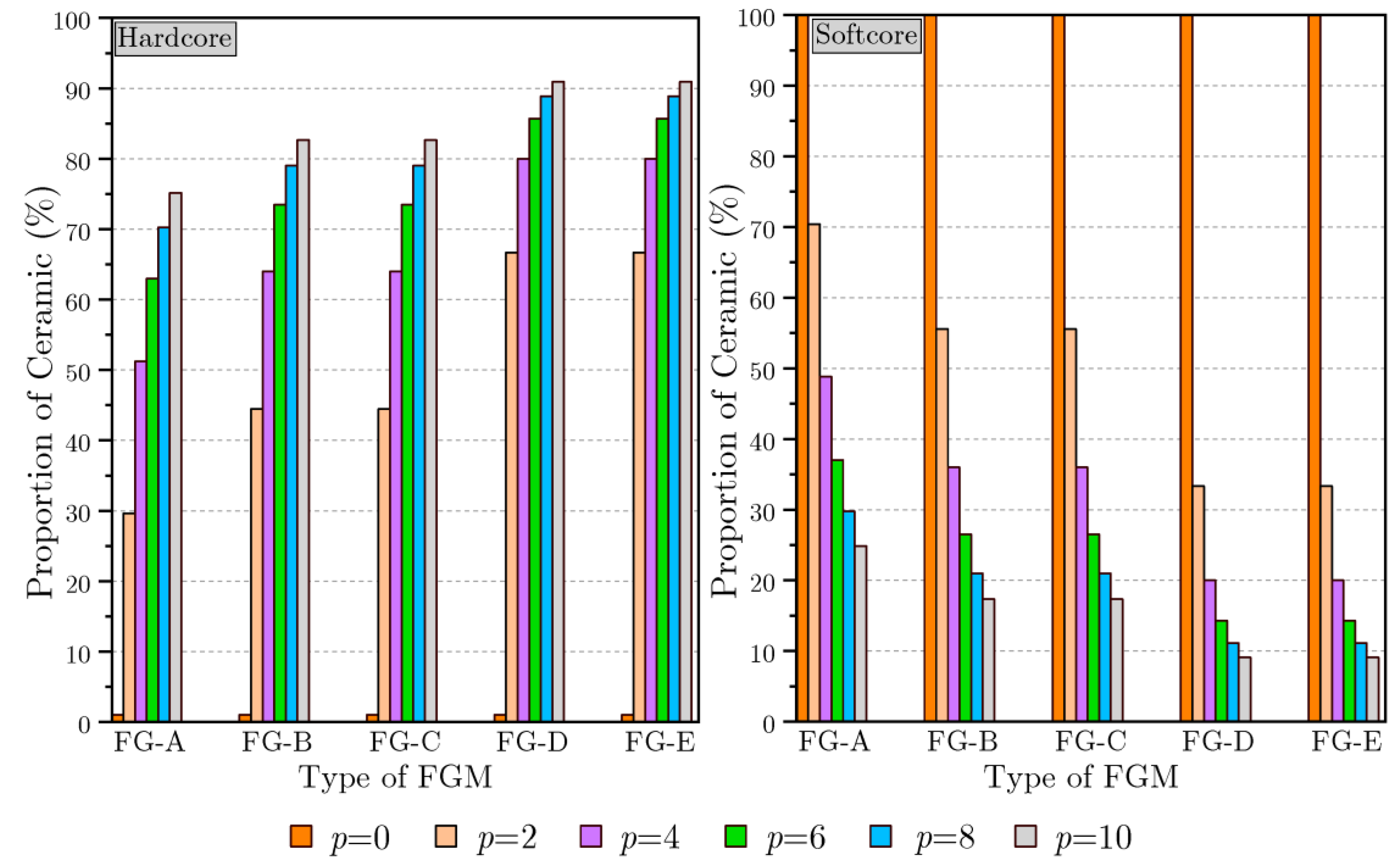
To understand more about the combination of the gradient materials that was related to the inhomogeneity parameters p, k, and e, Figure 4 was plotted to present the ceramic constituent proportion (%) in the various coated FG structures. This will help to explain the response of the mechanical nanoshells in the next analysis.
Figure 5 plots the variation in the critical buckling load of various configurations of coated FG shells influenced by the various inhomogeneity material exponents p, k, and e (p = k = e). The case of p = k = e = 0 for the hard core shells meant that the shells were fully metal, while for the soft core shells, they were fully ceramic. For the hard core coated FG shells, it was seen that the buckling loads increased due to the increase in the various material exponents p, k, and e wherever the FG shell scheme was. The maximum and the minimum critical buckling load values were for the b-coated FG-E shell and the tridirectional coated (tricoated) FG-A shell, respectively. The distribution of the materials in conjunction with the proportion of the materials played an important role in the response of the FG shell; this could explain the low stiffness of the FG-A shell and therefore the high buckling load. In the same case, the proportion of the ceramic was very high in the entire shell compared to the other shells (See Figure 4), and the top and bottom surfaces were fully ceramic. The inverse response was observed for the soft core shells.
5.3. Effects of Geometrical Parameters and the Extensity of the Applied Loads
The effects of the radius of curvature “R”, the thickness and aspect ratios “a/h” and “b/a”, and different boundary conditions on the various types of coated FG shells are presented in Table 4, Table 5 and Table 6, respectively, and for further clarification, the obtained results were translated into Figure 6, Figure 7 and Figure 8.
The impact of the radius of curvature ratio () and various coating schemes on the buckling response of the hard core or soft core coated shells is plotted in Figure 6. It should be noted that an increase in the radius of curvature necessarily meant that the shell gradually lost its curvature until the shell became a plate (. As shown in Figure 6, the values of the critical buckling loads were reduced by the increase in the radius of curvature for both the hard core and soft core shells. The effect of the ratio was neglected for values more than 18.
In Figure 7, the action of the side-to-thickness “a/h” and aspect “b/a” ratios on the buckling loads of various patterns of simply supported soft core coated FG shells is plotted. It is clear that the increase in both the aspect “b/a” and side-to-thickness “a/h” ratios increased the dimensionless critical loads.
The impact of the intensity of the axially applied load on the dimensionless critical buckling load of the coated FG shells is presented in Figure 8. It can be seen that for all of the coated shell types, the increase in the intensity of the applied loads led to a decrease in the critical buckling load.
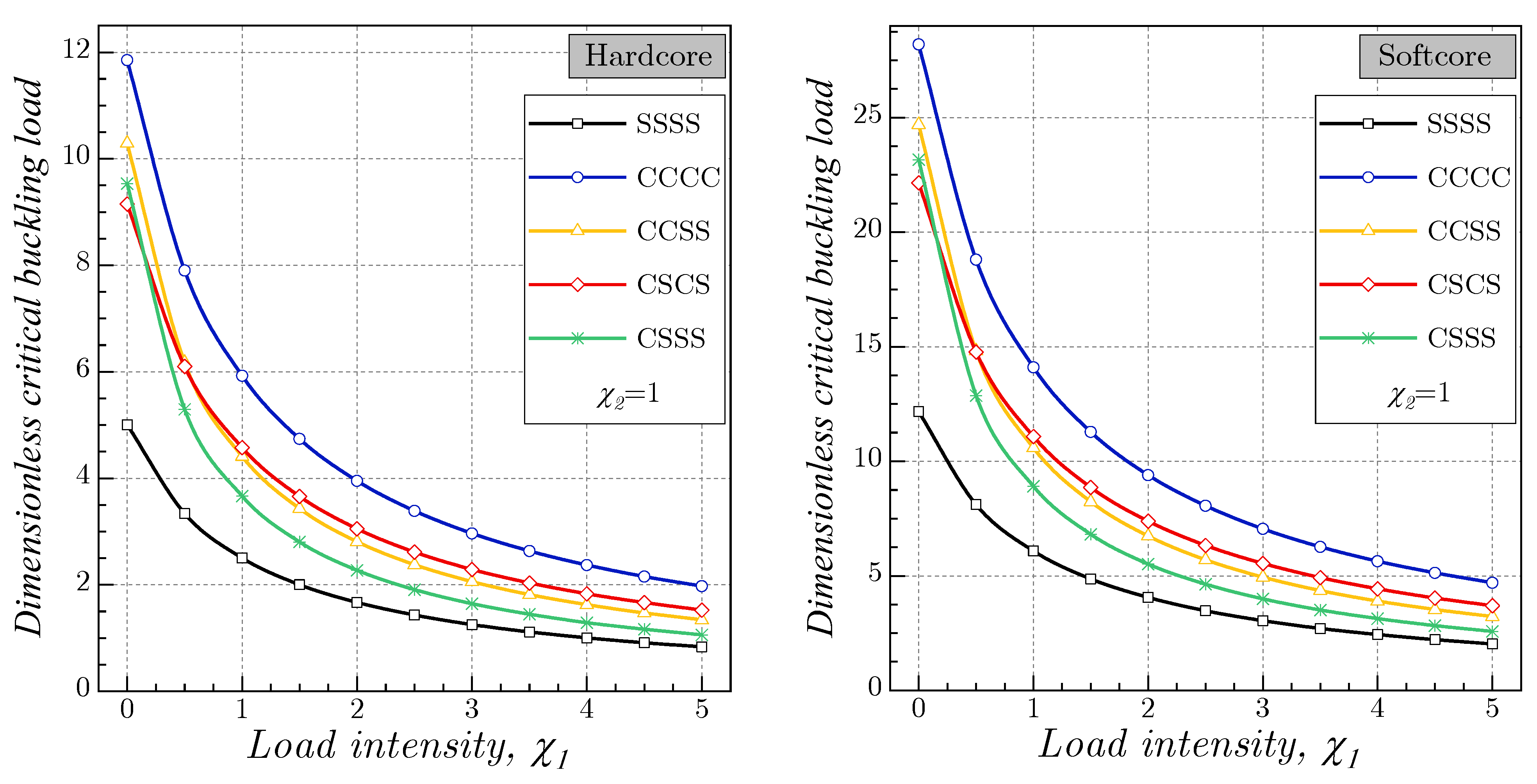
In Figure 9, the effects of the various boundary conditions and the intensity of the applied load on the dimensionless critical buckling load of the coated FG-A shells is illustrated. The minimal required loads to buckle were observed for the case of the simply supported shells (SSSS) due to their low rigidity, whereas the maximum buckling loads were observed for the case of the fully clamped coated shells (CCCC). It is worth noting that the analytical solution proposed by Melaibari et al. [30] was used to calculate the critical buckling loads of the shells with asymmetrical boundary conditions (CCSS and CSSS).
5.4. Effect of the Nanoscale
The dimensionless critical buckling load “” of the simply supported coated FG nanoshells influenced by the nonlocal and length-scale parameters is shown in Table 7 for various distribution patterns.
By considering the size-dependent impact, the buckling response ) of the soft core coated FG nanoshells was plotted in Figure 10 by varying the length scale and the nonlocal parameters. It is worth mentioning that the stiffness of the nanoshell was influenced by the length scale and the nonlocal parameters: the augmentation of the nonlocal parameter led to a decrease in the critical buckling loads due to the reduction in the rigidity of the nanoshell. The inverse impact was detected as an increase in the length-scale parameter where the rigidity was augmented wherever the shell scheme was.
Figure 11 presents the combination effect of the nanoshell size and the simply supported and/or clamped boundary conditions on the buckling behavior of the soft core coated FG-A nanoshells. In this figure, it can be observed that the fully clamped nanoshell was more rigid than the simply supported one, and this could explain the highest values of the critical buckling loads of the CCCC nanoshells.
5.5. Effect of the Winkler/Orthotropic Elastic Foundation
In order to examine the mechanical response of the coated FG shells resting on a Winkler/orthotropic foundation, a parametric study was performed by varying the foundation parameters such the Winkler foundation parameter , the two orthotropic Pasternak foundation parameters and , and the orthotropy direction θ (which was changed from 0° to 90°). Table 8 illustrates the influence of the mentioned parameters on the critical buckling load. For a better view of the impact of the elastic foundation on the buckling responses of the coated FG shells, Figure 11, Figure 12, Figure 13 and Figure 14 were plotted.
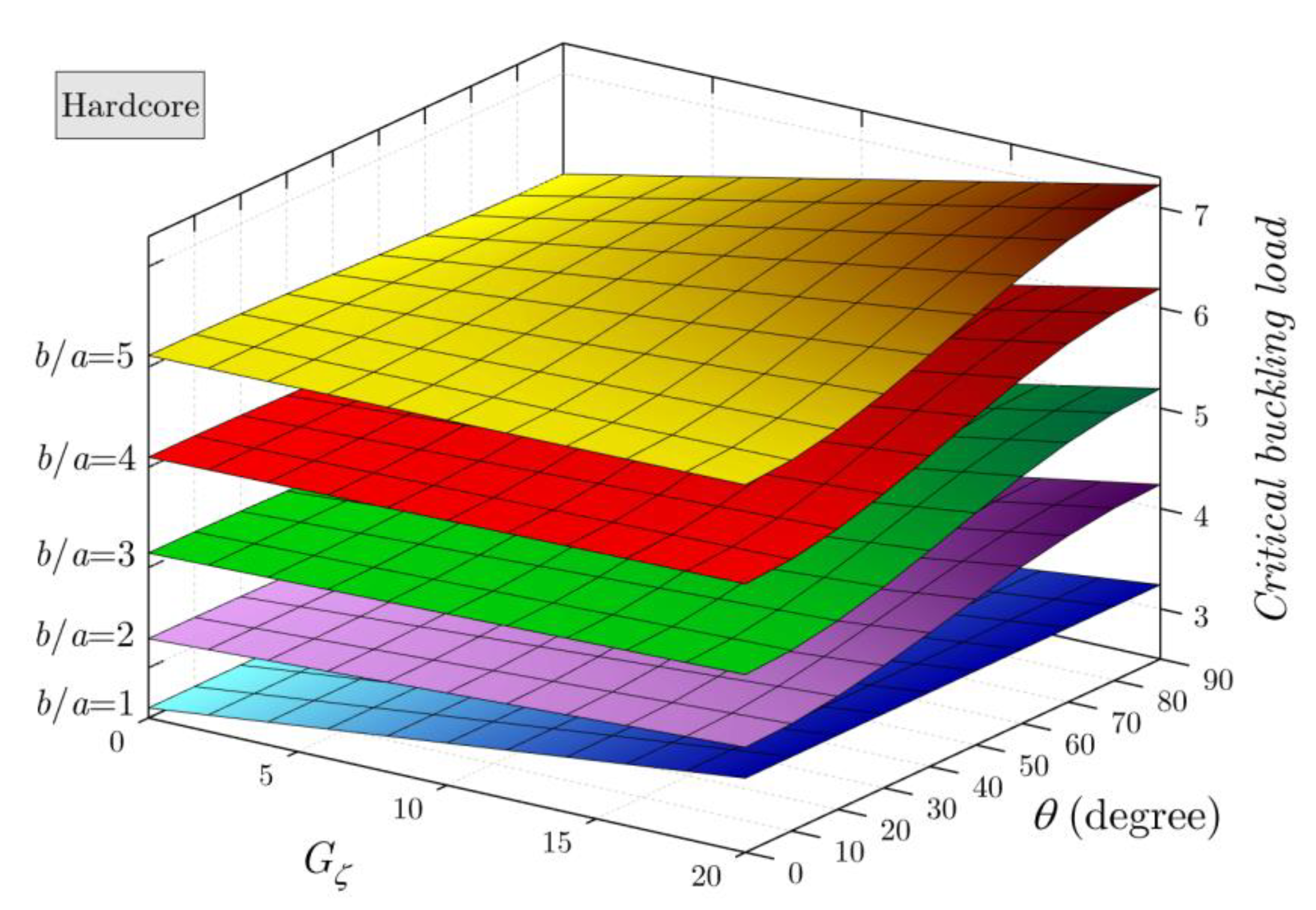
One of the objectives of this work was an in-depth analysis of the effects of various coefficients of the orthotropic elastic foundation on the buckling response of the coated shells (Figure 12, Figure 13, Figure 14 and Figure 15). Figure 12 shows the effects of the orthotropy direction “θ”, the orthotropic elastic foundation parameter , and the Winkler foundation parameter on the dimensionless buckling load of the hard core coated FG-A shells. It can be seen that the orthotropic foundation parameter had a greater influence on the buckling response than any other foundation parameter: the increase in the Winkler/orthotropic foundation parameters led to an increase in the stiffness of the shell; therefore, the critical buckling load increased.
For further analysis, Figure 13 was plotted to view the action of the aspect ratio on the intensity of the orthotropy direction “θ” and therefore the critical buckling loads. The orthotropy direction “θ” was changed from 0° to 90°. It can be seen that the orthotropy direction had no influence on the buckling response in the case of shells with equal edges (b/a = 1); therefore, the increase in the ratio b/a supported the effect of the orthotropy direction on the buckling loads, which were augmented by the augmentation of the orthotropy direction “θ”.
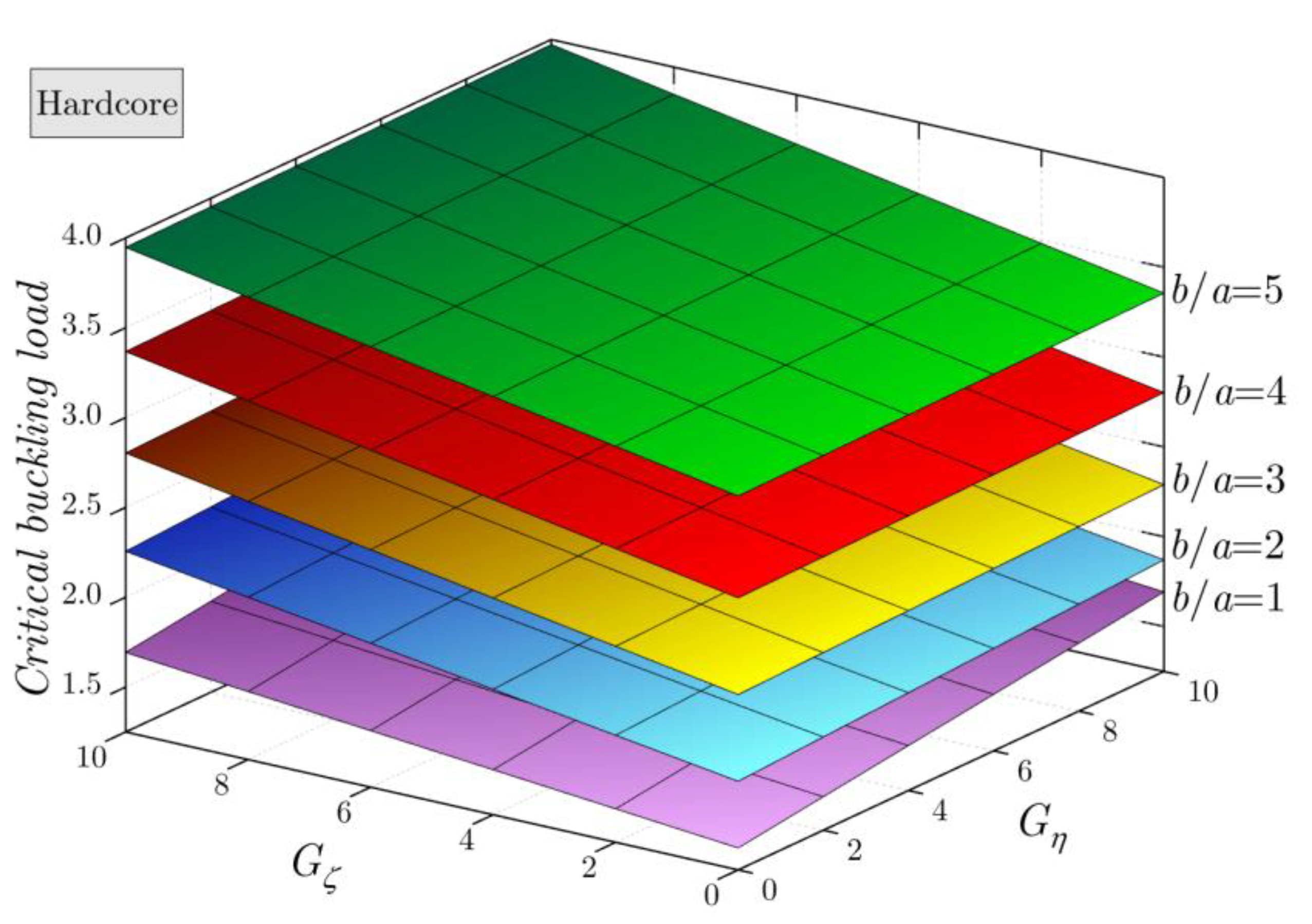
Figure 14 presents the impact of the orthotropic elastic foundation parameters and on the buckling response of the simply supported hard core coated FG-A shells for various aspect ratios b/a. The same effect of the orthotropic elastic foundation parameters and was observed in the case of aspect ratio b/a=1; whereas for the other cases when the ratio , the influence of the parameter was greater than the influence of the parameter .
The same analysis is presented in Figure 15, but this time the effect of the aspect ratio was replaced with the axial load intensity . It is worth mentioning that the critical buckling loads increased with the increase in the orthotropic elastic foundation parameters and in a linear manner. In addition, the axial load intensity had an important impact where the critical buckling loads decreased due to the augmentation of .
6. Conclusions
In the present work, an analytical analysis was developed for the buckling problem of tricoated FG spherical nanoshells resting on an orthotropic elastic foundation. A mathematical model of tricoated FG structures was proposed in this paper for the first time. Two patterns of material distribution were studied; namely, hard core and soft core bidirectionally coated shells, and a total of five schemes were considered. Based on the HSDT, a modified field of displacement was suggested based on four unknowns instead of five unknowns. To capture the size-dependent effect, the nonlocal strain gradient theory was employed. By applying the virtual work principle, the equilibrium equations were performed, and the obtained differential equations were solved by applying the Galerkin technique to cover all possible boundary conditions. The proposed Winkler/orthotropic elastic foundation was defined based on three parameters: one spring constant and two shear parameters referring to the orthotropy directions. Based on the obtained numerical results, the following results were revealed:
- ➢
- Increasing material exponents p, k, and e led to an increase in the critical buckling loads of the hard core structure and a decrease in the critical buckling loads of the soft core structure wherever the FG shell scheme was.
- ➢
- The critical buckling loads were reduced by the increase in the radius of curvature.
- ➢
- The increase in the intensity of the applied loads led to a decrease in the critical buckling loads.
- ➢
- The minimal values of the critical buckling loads were for the simply supported shells (SSSS), whereas the maximum buckling loads were for the fully clamped coated shells (CCCC).
- ➢
- The increase in the nonlocal parameter led to an increase in the critical buckling loads due to the reduction in the rigidity of the nanoshell, while the inverse impact was detected with an increase in the length-scale parameter.
- ➢
- The increase in the Winkler/ortho tropic foundation parameters led to an increase in the critical buckling loads; among various orthotropic foundation parameters, had a greater impact on the buckling response than any other foundation parameter.
Author Contributions
Conceptualization, A.A.D., M.A.E. and G.S.A.; Methodology, H.A.S. and M.A.E.; Software, A.A.D. and H.A.S.; Validation, A.A.D. and H.A.S.; Formal analysis, A.A.D. and M.A.E.; Resources, G.S.A.; Data curation, H.A.S.; Writing—original draft, A.A.D. and M.A.E.; Writing—review & editing, G.S.A. and H.A.S.; Visualization, M.A.E.; Funding acquisition, G.S.A. All authors have read and agreed to the published version of the manuscript.
Funding
The Institutional Fund Projects under grant no. IFPIP (406-135-1443).
Data Availability Statement
Not applicable.
Acknowledgments
This research was funded by the Institutional Fund Projects under grant no. IFPIP (406-135-1443). The authors gratefully acknowledge the technical and financial support provided by the Ministry of Education and King Abdulaziz University, DSR, in Jeddah, Saudi Arabia.
Conflicts of Interest
The authors declare no conflict of interest.
Appendix A
Orthotropic foundation:
The elements :
References
- Punera, D.; Kant, T. A critical review of stress and vibration analyses of functionally graded shell structures. Compos. Struct. 2019, 210, 787–809. [Google Scholar] [CrossRef]
- Ye, T.; Jin, G.; Su, Z. Three-dimensional vibration analysis of laminated functionally graded spherical shells with general boundary conditions. Compos. Struct. 2014, 116, 571–588. [Google Scholar] [CrossRef]
- Esen, I.; Özarpa, C.; Eltaher, M.A. Free vibration of a cracked FG microbeam embedded in an elastic matrix and exposed to magnetic field in a thermal environment. Compos. Struct. 2021, 261, 113552. [Google Scholar] [CrossRef]
- Melaibari, A.; Daikh, A.A.; Basha, M.; Abdalla, A.W.; Othman, R.; Almitani, K.H.; Hamed, M.A.; Abdelrahman, A.; Eltaher, M.A. Free Vibration of FG-CNTRCs Nano-Plates/Shells with Temperature-Dependent Properties. Mathematics 2022, 10, 583. [Google Scholar] [CrossRef]
- Zhao, T.; Luo, J.; Xiao, Z. Buckling Analysis of a Nanowire Lying on Winkler–Pasternak Elastic Foundation. Mech. Adv. Mater. Struct. 2015, 22, 394–401. [Google Scholar] [CrossRef] [Green Version]
- Nguyen, T.N.; Dang, L.M.; Lee, J.; Van Nguyen, P. Load-Carrying Capacity of Ultra-Thin Shells with and without CNTs Reinforcement. Mathematics 2022, 10, 1481. [Google Scholar] [CrossRef]
- Ansari, R.; Gholami, R.; Norouzzadeh, A. Size-dependent thermo-mechanical vibration and instability of conveying fluid functionally graded nanoshells based on Mindlin’s strain gradient theory. Thin-Walled Struct. 2016, 105, 172–184. [Google Scholar] [CrossRef]
- Kar, V.R.; Panda, S.K. Nonlinear thermomechanical deformation behaviour of P-FGM shallow spherical shell panel. Chin. J. Aeronaut. 2016, 29, 173–183. [Google Scholar] [CrossRef] [Green Version]
- Fattahi, A.M.; Sahmani, S. Nonlocal temperature-dependent postbuckling behavior of FG-CNT reinforced nanoshells under hydrostatic pressure combined with heat conduction. Microsyst. Technol. 2017, 23, 5121–5137. [Google Scholar] [CrossRef]
- Faleh, N.M.; Ahmed, R.A.; Fenjan, R.M. On vibrations of porous FG nanoshells. Int. J. Eng. Sci. 2018, 133, 1–14. [Google Scholar] [CrossRef]
- Barati, M.R. Vibration analysis of porous FG nanoshells with even and uneven porosity distributions using nonlocal strain gradient elasticity. Acta Mech. 2018, 229, 1183–1196. [Google Scholar] [CrossRef]
- Sahmani, S.; Aghdam, M. Boundary Layer Modeling of Nonlinear Axial Buckling Behavior of Functionally Graded Cylindrical Nanoshells Based on the Surface Elasticity Theory. Iran. J. Sci. Technol. Trans. Mech. Eng. 2018, 42, 229–245. [Google Scholar] [CrossRef]
- Blooriyan, S.; Ansari, R.; Darvizeh, A.; Gholami, R.; Rouhi, H. Pre- and post-buckling analysis of FG cylindrical nanoshells in thermal environment considering the surface stress effect. Mater. Res. Express 2019, 6, 095067. [Google Scholar] [CrossRef]
- Karami, B.; Janghorban, M.; Tounsi, A. On pre-stressed functionally graded anisotropic nanoshell in magnetic field. J. Braz. Soc. Mech. Sci. Eng. 2019, 41, 495. [Google Scholar] [CrossRef]
- Lu, L.; Zhu, L.; Guo, X.; Zhao, J.; Liu, G. A nonlocal strain gradient shell model incorporating surface effects for vibration analysis of functionally graded cylindrical nanoshells. Appl. Math. Mech. 2019, 40, 1695–1722. [Google Scholar] [CrossRef] [Green Version]
- Safarpour, H.; Hajilak, Z.E.; Habibi, M. A size-dependent exact theory for thermal buckling, free and forced vibration analysis of temperature dependent FG multilayer GPLRC composite nanostructures restring on elastic foundation. Int. J. Mech. Mater. Des. 2019, 15, 569–583. [Google Scholar] [CrossRef]
- Sahmani, S.; Fattahi, A.; Ahmed, N. Surface elastic shell model for nonlinear primary resonant dynamics of FG porous nanoshells incorporating modal interactions. Int. J. Mech. Sci. 2019, 165, 105203. [Google Scholar] [CrossRef]
- Forsat, M.; Badnava, S.; Mirjavadi, S.S.; Barati, M.R.; Hamouda, A.M. Small scale effects on transient vibrations of porous FG cylindrical nanoshells based on nonlocal strain gradient theory. Eur. Phys. J. Plus 2020, 135, 81. [Google Scholar] [CrossRef]
- Karami, B.; Shahsavari, D. On the forced resonant vibration analysis of functionally graded polymer composite doubly-curved nanoshells reinforced with graphene-nanoplatelets. Comput. Methods Appl. Mech. Eng. 2020, 359, 112767. [Google Scholar] [CrossRef]
- Karami, B.; Janghorban, M. On the mechanics of functionally graded nanoshells. Int. J. Eng. Sci. 2020, 153, 103309. [Google Scholar] [CrossRef]
- Li, Q.; Xie, B.; Sahmani, S.; Safaei, B. Surface stress effect on the nonlinear free vibrations of functionally graded composite nanoshells in the presence of modal interaction. J. Braz. Soc. Mech. Sci. Eng. 2020, 42, 237. [Google Scholar] [CrossRef]
- Dindarloo, M.H.; Zenkour, A.M. Nonlocal strain gradient shell theory for bending analysis of FG spherical nanoshells in thermal environment. Eur. Phys. J. Plus 2020, 135, 785. [Google Scholar] [CrossRef]
- Arefi, M.; Talkhunche, G.G. Higher-order vibration analysis of FG cylindrical nano-shell. Eur. Phys. J. Plus 2021, 136, 154. [Google Scholar] [CrossRef]
- Cao, Y.; Khorami, M.; Baharom, S.; Assilzadeh, H.; Dindarloo, M.H. The effects of multi-directional functionally graded materials on the natural frequency of the doubly-curved nanoshells. Compos. Struct. 2021, 258, 113403. [Google Scholar] [CrossRef]
- Heidari, Y.; Arefi, M.; Rahaghi, M.I. Effect of distributed piezoelectric segments on the buckling load of FG cylindrical micro/nano shell. Eur. Phys. J. Plus 2021, 136, 74. [Google Scholar] [CrossRef]
- Zou, D.; Dindarloo, M.H. Static analysis of the FG with spatial coordinates cylindrical nanoshells in thermal environment. Mech. Based Des. Struct. Mach. 2021. [Google Scholar] [CrossRef]
- Arefi, M.; Bidgoli, E.M.-R.; Civalek, O. Bending response of FG composite doubly curved nanoshells with thickness stretching via higher-order sinusoidal shear theory. Mech. Based Des. Struct. Mach. 2022, 50, 2350–2378. [Google Scholar] [CrossRef]
- Daikh, A.A.; Houari, M.S.A.; Belarbi, M.O.; Chakraverty, S.; Eltaher, M.A. Analysis of axially temperature-dependent functionally graded carbon nanotube reinforced composite plates. Eng. Comput. 2022, 38, 2533–2554. [Google Scholar] [CrossRef]
- Ghandourah, E.E.; Daikh, A.A.; Alhawsawi, A.M.; Fallatah, O.A.; Eltaher, M.A. Bending and Buckling of FG-GRNC Laminated Plates via Quasi-3D Nonlocal Strain Gradient Theory. Mathematics 2022, 10, 1321. [Google Scholar] [CrossRef]
- Shi, X.; Li, J.; Habibi, M. On the statics and dynamics of an electro-thermo-mechanically porous GPLRC nanoshell conveying fluid flow. Mech. Based Des. Struct. Mach. 2022, 50, 2147–2183. [Google Scholar] [CrossRef]
- Melaibari, A.; Daikh, A.A.; Basha, M.; Wagih, A.; Othman, R.; Almitani, K.H.; Hamed, M.A.; Abdelrahman, A.; Eltaher, M.A. A Dynamic Analysis of Randomly Oriented Functionally Graded Carbon Nanotubes/Fiber-Reinforced Composite Laminated Shells with Different Geometries. Mathematics 2022, 10, 408. [Google Scholar] [CrossRef]
- Yang, S.; Hao, Y.; Zhang, W.; Liu, L.; Ma, W. Static and Dynamic Stability of Carbon Fiber Reinforced Polymer Cylindrical Shell Subject to Non-Normal Boundary Condition with One Generatrix Clamped. Mathematics 2022, 10, 1531. [Google Scholar] [CrossRef]
- Daikh, A.-A.; Belarbi, M.-O.; Ahmed, D.; Houari, M.S.A.; Avcar, M.; Tounsi, A.; Eltaher, M.A. Static analysis of functionally graded plate structures resting on variable elastic foundation under various boundary conditions. Acta Mech. 2022. [Google Scholar] [CrossRef]
- Kutlu, A.; Uğurlu, B.; Omurtag, M.; Ergin, A. Dynamic response of Mindlin plates resting on arbitrarily orthotropic Pasternak foundation and partially in contact with fluid. Ocean Eng. 2012, 42, 112–125. [Google Scholar] [CrossRef]
- Thai, H.-T.; Choi, D.-H. An efficient and simple refined theory for buckling analysis of functionally graded plates. Appl. Math. Model. 2012, 36, 1008–1022. [Google Scholar] [CrossRef]
Figure 1.
FG spherical shell geometry.

Figure 2.
Five schemes of coated FG shell .

Figure 3.
Functionally graded material distribution.

Figure 4.
The proportion of ceramic (%) in various types of FG structures .

Figure 5.
Dimensionless critical buckling load of FG shells for various material exponents p, k, and e.
Figure 5.
Dimensionless critical buckling load of FG shells for various material exponents p, k, and e.

Figure 6.
Dimensionless critical buckling load of FG shells versus radius of curvature ratio .

Figure 7.
Effect of the shell geometry on the dimensionless critical buckling load of coated FG shells .
Figure 7.
Effect of the shell geometry on the dimensionless critical buckling load of coated FG shells .

Figure 8.
Effect of the intensity of the applied load on the dimensionless critical buckling load of FG shells .
Figure 8.
Effect of the intensity of the applied load on the dimensionless critical buckling load of FG shells .

Figure 9.
Effect of the intensity of the applied load on the dimensionless critical buckling load of tricoated FG-A shells for various boundary conditions .
Figure 9.
Effect of the intensity of the applied load on the dimensionless critical buckling load of tricoated FG-A shells for various boundary conditions .

Figure 10.
Effect of the nonlocal and length-scale parameters on the dimensionless critical buckling load of FG nanoshells .
Figure 10.
Effect of the nonlocal and length-scale parameters on the dimensionless critical buckling load of FG nanoshells .

Figure 11.
Effect of the nonlocal and length-scale parameters for various boundary conditions .

Figure 12.
Effect of the orthotropic elastic foundation on the dimensionless critical buckling load of coated FG shells .
Figure 12.
Effect of the orthotropic elastic foundation on the dimensionless critical buckling load of coated FG shells .

Figure 13.
Effect of the orthotropic elastic foundation for various aspect ratios b/a.

Figure 14.
Effect of the orthotropic elastic foundation parameters and for various aspect ratios b/a.
Figure 14.
Effect of the orthotropic elastic foundation parameters and for various aspect ratios b/a.

Figure 15.
Effect of the orthotropic elastic foundation parameters and for various values of load intensity .
Figure 15.
Effect of the orthotropic elastic foundation parameters and for various values of load intensity .


Table 1.
The admissible functions and for different boundary conditions.
| Boundary Conditions | ||||
|---|---|---|---|---|
| At | At | |||
| SSSS | ||||
| CCCC | ||||
| CCSS | ||||
Note: and .
Table 2.
Comparison of the dimensionless critical buckling loads for simply supported Al2O3 ceramic plates ( and ).
Table 2.
Comparison of the dimensionless critical buckling loads for simply supported Al2O3 ceramic plates ( and ).
| Theories | ||||||
|---|---|---|---|---|---|---|
| 0.5 | Thai and Choi [35] | 5.3762 | 5.9243 | 6.0794 | 6.1244 | 6.1308 |
| Present | 5.3774 | 5.9246 | 6.0795 | 6.1244 | 6.1308 | |
| 1 | Thai and Choi [35] | 8.0105 | 9.2893 | 9.6764 | 9.7907 | 9.8073 |
| Present | 8.0135 | 9.2900 | 9.6766 | 9.7907 | 9.8073 | |
| 1.5 | Thai and Choi [35] | 11.6820 | 14.6084 | 15.5887 | 15.8876 | 15.9312 |
| Present | 11.6895 | 14.6105 | 15.5892 | 15.8876 | 15.9312 | |
| 2 | Thai and Choi [35] | 15.7235 | 21.5050 | 23.6970 | 24.3944 | 24.4974 |
| Present | 15.7400 | 21.5097 | 23.6983 | 24.3946 | 24.4975 | |
Table 3.
Dimensionless critical buckling load of FG shells versus exponents , , and
| FG-A | FG-B | FG-C | FG-D | FG-E | FG-A | FG- B | FG-C | FG-D | FG-E | |||
| 2 | 2 | 2 | 2.5031 | 3.9768 | 3.0811 | 3.9472 | 5.2953 | 6.0809 | 4.6360 | 5.4681 | 4.4814 | 3.3175 |
| 5 | 2.7922 | 4.6360 | 3.0811 | 3.9472 | 5.2953 | 5.7767 | 3.9768 | 5.4681 | 4.4814 | 3.3175 | ||
| 10 | 2.9235 | 4.9357 | 3.0811 | 3.9472 | 5.2953 | 5.6371 | 3.6771 | 5.4681 | 4.4814 | 3.3175 | ||
| 5 | 2 | 2.7922 | 4.6360 | 3.5142 | 3.9472 | 6.2842 | 5.7767 | 3.9768 | 4.9913 | 4.4814 | 2.3287 | |
| 5 | 3.1533 | 5.4601 | 3.5142 | 3.9472 | 6.2842 | 5.3900 | 3.1527 | 4.9913 | 4.4814 | 2.3287 | ||
| 10 | 3.3174 | 5.8347 | 3.5142 | 3.9472 | 6.2842 | 5.2107 | 2.7781 | 4.9913 | 4.4814 | 2.3287 | ||
| 10 | 2 | 2.9235 | 4.9357 | 3.7110 | 3.9472 | 6.7337 | 5.6371 | 3.6771 | 4.7655 | 4.4814 | 1.8792 | |
| 5 | 3.3174 | 5.8347 | 3.7110 | 3.9472 | 6.7337 | 5.2107 | 2.7781 | 4.7655 | 4.4814 | 1.8792 | ||
| 10 | 3.4963 | 6.2433 | 3.7110 | 3.9472 | 6.7337 | 5.0115 | 2.3695 | 4.7655 | 4.4814 | 1.8792 | ||
| 5 | 2 | 2 | 3.0731 | 3.9768 | 3.9382 | 5.2354 | 5.2953 | 5.5250 | 4.6360 | 4.6407 | 3.2550 | 3.3175 |
| 5 | 3.5057 | 4.6360 | 3.9382 | 5.2354 | 5.2953 | 5.0844 | 3.9768 | 4.6407 | 3.2550 | 3.3175 | ||
| 10 | 3.7023 | 4.9357 | 3.9382 | 5.2354 | 5.2953 | 4.8832 | 3.6771 | 4.6407 | 3.2550 | 3.3175 | ||
| 5 | 2 | 3.5057 | 4.6360 | 4.5869 | 5.2354 | 6.2842 | 5.0844 | 3.9768 | 3.9645 | 3.2550 | 2.3287 | |
| 5 | 4.0463 | 5.4601 | 4.5869 | 5.2354 | 6.2842 | 4.5291 | 3.1527 | 3.9645 | 3.2550 | 2.3287 | ||
| 10 | 4.2920 | 5.8347 | 4.5869 | 5.2354 | 6.2842 | 4.2741 | 2.7781 | 3.9645 | 3.2550 | 2.3287 | ||
| 10 | 2 | 3.7023 | 4.9357 | 4.8817 | 5.2354 | 6.7337 | 4.8832 | 3.6771 | 3.6488 | 3.2550 | 1.8792 | |
| 5 | 4.2920 | 5.8347 | 4.8817 | 5.2354 | 6.7337 | 4.2741 | 2.7781 | 3.6488 | 3.2550 | 1.8792 | ||
| 10 | 4.5601 | 6.2433 | 4.8817 | 5.2354 | 6.7337 | 3.9928 | 2.3695 | 3.6488 | 3.2550 | 1.8792 | ||
| 10 | 2 | 2 | 3.4254 | 3.9768 | 4.4676 | 6.0308 | 5.2953 | 5.1816 | 4.6360 | 4.1316 | 2.5294 | 3.3175 |
| 5 | 3.9465 | 4.6360 | 4.4676 | 6.0308 | 5.2953 | 4.6573 | 3.9768 | 4.1316 | 2.5294 | 3.3175 | ||
| 10 | 4.1834 | 4.9357 | 4.4676 | 6.0308 | 5.2953 | 4.4185 | 3.6771 | 4.1316 | 2.5294 | 3.3175 | ||
| 5 | 2 | 3.9465 | 4.6360 | 5.2492 | 6.0308 | 6.2842 | 4.6573 | 3.9768 | 3.3385 | 2.5294 | 2.3287 | |
| 5 | 4.5979 | 5.4601 | 5.2492 | 6.0308 | 6.2842 | 3.9999 | 3.1527 | 3.3385 | 2.5294 | 2.3287 | ||
| 10 | 4.8940 | 5.8347 | 5.2492 | 6.0308 | 6.2842 | 3.7000 | 2.7781 | 3.3385 | 2.5294 | 2.3287 | ||
| 10 | 2 | 4.1834 | 4.9357 | 5.6045 | 6.0308 | 6.7337 | 4.4185 | 3.6771 | 2.9741 | 2.5294 | 1.8792 | |
| 5 | 4.8940 | 5.8347 | 5.6045 | 6.0308 | 6.7337 | 3.7000 | 2.7781 | 2.9741 | 2.5294 | 1.8792 | ||
| 10 | 5.2169 | 6.2433 | 5.6045 | 6.0308 | 6.7337 | 3.3714 | 2.3695 | 2.9741 | 2.5294 | 1.8792 | ||
Table 4.
Dimensionless critical buckling load of FG shells for various radii of curvature .
| FG-A | FG-B | FG-C | FG-D | FG-E | FG-A | FG-B | FG-C | FG-D | FG-E | ||
|---|---|---|---|---|---|---|---|---|---|---|---|
| 5 | 2 | 2.5031 | 3.9768 | 3.0811 | 3.9472 | 5.2953 | 6.0809 | 4.6360 | 5.4681 | 4.4814 | 3.3175 |
| 5 | 4.0463 | 5.4601 | 4.5869 | 5.2354 | 6.2842 | 4.5291 | 3.1527 | 3.9645 | 3.2550 | 2.3287 | |
| 10 | 5.2169 | 6.2433 | 5.6045 | 6.0308 | 6.7337 | 3.3714 | 2.3695 | 2.9741 | 2.5294 | 1.8792 | |
| 10 | 2 | 2.2571 | 3.6610 | 2.7653 | 3.5267 | 4.8748 | 5.6429 | 4.2679 | 5.1000 | 4.2180 | 3.0541 |
| 5 | 3.6673 | 5.0265 | 4.1533 | 4.7364 | 5.7852 | 4.2242 | 2.9024 | 3.7141 | 3.0701 | 2.1437 | |
| 10 | 4.7566 | 5.7476 | 5.1087 | 5.4961 | 6.1990 | 3.1479 | 2.1814 | 2.7859 | 2.3802 | 1.7299 | |
| 20 | 2 | 2.1956 | 3.5821 | 2.6864 | 3.4216 | 4.7697 | 5.5335 | 4.1759 | 5.0079 | 4.1521 | 2.9882 |
| 5 | 3.5725 | 4.9181 | 4.0449 | 4.6117 | 5.6604 | 4.1480 | 2.8398 | 3.6515 | 3.0239 | 2.0975 | |
| 10 | 4.6415 | 5.6236 | 4.9848 | 5.3624 | 6.0653 | 3.0920 | 2.1343 | 2.7389 | 2.3429 | 1.6926 | |
| 50 | 2 | 2.1784 | 3.5600 | 2.6643 | 3.3921 | 4.7403 | 5.5028 | 4.1501 | 4.9822 | 4.1337 | 2.9698 |
| 5 | 3.5460 | 4.8878 | 4.0145 | 4.5768 | 5.6255 | 4.1267 | 2.8223 | 3.6340 | 3.0109 | 2.0846 | |
| 10 | 4.6093 | 5.5889 | 4.9501 | 5.3250 | 6.0279 | 3.0763 | 2.1212 | 2.7257 | 2.3324 | 1.6822 | |
| Inf. | 2 | 2.1751 | 3.5557 | 2.6600 | 3.3865 | 4.7347 | 5.4970 | 4.1452 | 4.9772 | 4.1301 | 2.9663 |
| 5 | 3.5409 | 4.8820 | 4.0088 | 4.5701 | 5.6188 | 4.1226 | 2.8189 | 3.6307 | 3.0085 | 2.0821 | |
| 10 | 4.6031 | 5.5823 | 4.9435 | 5.3179 | 6.0207 | 3.0734 | 2.1186 | 2.7232 | 2.3304 | 1.6802 | |
Table 5.
Dimensionless critical buckling load of FG shells versus the aspect and the thickness ratios .
Table 5.
Dimensionless critical buckling load of FG shells versus the aspect and the thickness ratios .
| FG-A | FG-B | FG-C | FG-D | FG-E | FG-A | FG-B | FG-C | FG-D | FG-E | ||
|---|---|---|---|---|---|---|---|---|---|---|---|
| 5 | 0.5 | 2.0494 | 3.0425 | 2.5433 | 3.2787 | 4.0513 | 4.4176 | 3.5469 | 3.7871 | 2.6684 | 2.5382 |
| 1 | 2.0338 | 3.1724 | 2.5059 | 3.2113 | 4.2242 | 4.7605 | 3.6983 | 4.1995 | 3.2154 | 2.6465 | |
| 2 | 2.6661 | 4.2377 | 3.2758 | 4.1878 | 5.6427 | 6.4389 | 4.9402 | 5.7433 | 4.5493 | 3.5352 | |
| 3 | 3.5344 | 5.6555 | 4.3373 | 5.5385 | 7.5306 | 8.6245 | 6.5931 | 7.7154 | 6.1625 | 4.7180 | |
| 10 | 0.5 | 2.6661 | 4.2377 | 3.2758 | 4.1878 | 5.6427 | 6.4389 | 4.9402 | 5.7433 | 4.5493 | 3.5352 |
| 1 | 2.5031 | 3.9768 | 3.0811 | 3.9472 | 5.2953 | 6.0809 | 4.6360 | 5.4681 | 4.4814 | 3.3175 | |
| 2 | 3.1362 | 5.0203 | 3.8557 | 4.9341 | 6.6848 | 7.7127 | 5.8525 | 6.9643 | 5.7839 | 4.1880 | |
| 3 | 3.9711 | 6.4337 | 4.8694 | 6.2159 | 8.5668 | 9.9341 | 7.5002 | 9.0012 | 7.5321 | 5.3671 | |
| 20 | 0.5 | 3.1362 | 5.0203 | 3.8557 | 4.9341 | 6.6848 | 7.7127 | 5.8525 | 6.9643 | 5.7839 | 4.1880 |
| 1 | 3.5512 | 5.3879 | 4.4182 | 5.7185 | 7.1742 | 8.1096 | 6.2811 | 7.2328 | 5.8971 | 4.4947 | |
| 2 | 4.3208 | 6.5940 | 5.3696 | 6.9427 | 8.7803 | 9.9540 | 7.6871 | 8.8973 | 7.2960 | 5.5009 | |
| 3 | 4.8820 | 7.6663 | 6.0307 | 7.7535 | 10.2080 | 11.7140 | 8.9372 | 10.5560 | 8.7994 | 6.3954 | |
| 30 | 0.5 | 3.6462 | 5.7138 | 4.5054 | 5.7938 | 7.6083 | 8.7175 | 6.6611 | 7.8447 | 6.5074 | 4.7666 |
| 1 | 5.2034 | 7.5219 | 6.5376 | 8.5388 | 10.0160 | 11.0840 | 8.7688 | 9.7450 | 7.7275 | 6.2749 | |
| 2 | 6.2196 | 9.0419 | 7.8060 | 10.1850 | 12.0400 | 13.3600 | 10.5410 | 11.7700 | 9.3781 | 7.5430 | |
| 3 | 6.3104 | 9.5121 | 7.8628 | 10.1910 | 12.6660 | 14.2870 | 11.0890 | 12.7310 | 10.3870 | 7.9352 | |
Table 6.
Dimensionless critical buckling load of FG shells for various boundary conditions .
| BCs. | |||||||||||
|---|---|---|---|---|---|---|---|---|---|---|---|
| FG-A | FG-B | FG-C | FG-D | FG-E | FG-A | FG-B | FG-C | FG-D | FG-E | ||
| SSSS | 2 | 2.5031 | 3.9768 | 3.0811 | 3.9472 | 5.2953 | 6.0809 | 4.6360 | 5.4681 | 4.4814 | 3.3175 |
| 5 | 4.0463 | 5.4601 | 4.5869 | 5.2354 | 6.2842 | 4.5291 | 3.1527 | 3.9645 | 3.2550 | 2.3287 | |
| 10 | 5.2169 | 6.2433 | 5.6045 | 6.0308 | 6.7337 | 3.3714 | 2.3695 | 2.9741 | 2.5294 | 1.8792 | |
| CCCC | 2 | 5.9277 | 9.3193 | 7.3005 | 9.3540 | 12.4090 | 14.0940 | 10.8640 | 12.5300 | 9.8541 | 7.7744 |
| 5 | 9.5520 | 12.7950 | 10.8300 | 12.3630 | 14.7270 | 10.4240 | 7.3882 | 9.0171 | 7.1748 | 5.4570 | |
| 10 | 12.2810 | 14.6310 | 13.1940 | 14.1990 | 15.7800 | 7.7670 | 5.5528 | 6.8014 | 5.7010 | 4.4037 | |
| CCSS | 2 | 4.4115 | 6.9682 | 5.4305 | 6.9554 | 9.2785 | 10.5790 | 8.1234 | 9.4414 | 7.5222 | 5.8130 |
| 5 | 7.1184 | 9.5673 | 8.0698 | 9.2113 | 11.0110 | 7.8440 | 5.5243 | 6.8117 | 5.4737 | 4.0803 | |
| 10 | 9.1638 | 10.9400 | 9.8449 | 10.5940 | 11.7990 | 5.8434 | 4.1519 | 5.1295 | 4.3197 | 3.2927 | |
| CSCS | 2 | 4.5756 | 7.2742 | 5.6246 | 7.1946 | 9.6859 | 11.0740 | 8.4801 | 9.9016 | 7.9195 | 6.0683 |
| 5 | 7.3949 | 9.9874 | 8.3810 | 9.5640 | 11.4950 | 8.2252 | 5.7668 | 7.1549 | 5.7662 | 4.2595 | |
| 10 | 9.5375 | 11.4200 | 10.2460 | 11.0250 | 12.3170 | 6.1291 | 4.3342 | 5.3868 | 4.5446 | 3.4373 | |
| CSSS | 2 | 3.6672 | 5.8362 | 4.5092 | 5.7699 | 7.7712 | 8.9058 | 6.8037 | 7.9840 | 6.4533 | 4.8687 |
| 5 | 5.9294 | 8.0131 | 6.7202 | 7.6691 | 9.2225 | 6.6243 | 4.6268 | 5.7787 | 4.6945 | 3.4175 | |
| 10 | 7.6492 | 9.1625 | 8.2171 | 8.8418 | 9.8821 | 4.9343 | 3.4774 | 4.3442 | 3.6781 | 2.7578 | |
Table 7.
Dimensionless critical buckling load of FG nanoshells versus nonlocal and length-scale parameters .
Table 7.
Dimensionless critical buckling load of FG nanoshells versus nonlocal and length-scale parameters .
| FG-A | FG-B | FG-C | FG-D | FG-E | FG-A | FG-B | FG-C | FG-D | FG-E | ||
|---|---|---|---|---|---|---|---|---|---|---|---|
| 0 | 0 | 2.5031 | 3.9768 | 3.0811 | 3.9472 | 5.2953 | 6.0809 | 4.6360 | 5.4681 | 4.4814 | 3.3175 |
| 0.5 | 2.8680 | 4.5179 | 3.5369 | 4.5392 | 6.0158 | 6.8845 | 5.2669 | 6.1768 | 5.0397 | 3.7690 | |
| 1 | 3.2390 | 5.0680 | 4.0003 | 5.1411 | 6.7483 | 7.7018 | 5.9082 | 6.8978 | 5.6090 | 4.2279 | |
| 1.5 | 3.6146 | 5.6251 | 4.4696 | 5.7507 | 7.4900 | 8.5296 | 6.5575 | 7.6284 | 6.1869 | 4.6926 | |
| 2 | 3.9939 | 6.1875 | 4.9434 | 6.3664 | 8.2390 | 9.3656 | 7.2133 | 8.3665 | 6.7715 | 5.1618 | |
| 0.5 | 0 | 2.2782 | 3.6196 | 2.8043 | 3.5926 | 4.8196 | 5.5346 | 4.2196 | 4.9769 | 4.0788 | 3.0195 |
| 0.5 | 2.6103 | 4.1121 | 3.2192 | 4.1314 | 5.4754 | 6.2661 | 4.7938 | 5.6219 | 4.5870 | 3.4304 | |
| 1 | 2.9480 | 4.6128 | 3.6409 | 4.6793 | 6.1421 | 7.0099 | 5.3774 | 6.2782 | 5.1052 | 3.8481 | |
| 1.5 | 3.2899 | 5.1198 | 4.0681 | 5.2341 | 6.8172 | 7.7634 | 5.9685 | 6.9431 | 5.6311 | 4.2710 | |
| 2 | 3.6352 | 5.6317 | 4.4994 | 5.7945 | 7.4989 | 8.5243 | 6.5653 | 7.6149 | 6.1632 | 4.6981 | |
| 1 | 0 | 2.0904 | 3.3212 | 2.5732 | 3.2965 | 4.4224 | 5.0784 | 3.8718 | 4.5667 | 3.7426 | 2.7706 |
| 0.5 | 2.3952 | 3.7731 | 2.9538 | 3.7909 | 5.0241 | 5.7496 | 4.3986 | 5.1585 | 4.2089 | 3.1476 | |
| 1 | 2.7050 | 4.2326 | 3.3408 | 4.2936 | 5.6359 | 6.4321 | 4.9342 | 5.7607 | 4.6844 | 3.5309 | |
| 1.5 | 3.0187 | 4.6978 | 3.7327 | 4.8027 | 6.2553 | 7.1235 | 5.4765 | 6.3709 | 5.1670 | 3.9190 | |
| 2 | 3.3355 | 5.1675 | 4.1285 | 5.3169 | 6.8808 | 7.8217 | 6.0242 | 6.9873 | 5.6552 | 4.3109 | |
| 1.5 | 0 | 1.9312 | 3.0683 | 2.3772 | 3.0454 | 4.0856 | 4.6917 | 3.5770 | 4.2189 | 3.4576 | 2.5597 |
| 0.5 | 2.2128 | 3.4858 | 2.7289 | 3.5022 | 4.6415 | 5.3118 | 4.0637 | 4.7657 | 3.8884 | 2.9080 | |
| 1 | 2.4990 | 3.9102 | 3.0864 | 3.9666 | 5.2067 | 5.9423 | 4.5585 | 5.3220 | 4.3276 | 3.2620 | |
| 1.5 | 2.7889 | 4.3400 | 3.4485 | 4.4370 | 5.7790 | 6.5810 | 5.0595 | 5.8857 | 4.7735 | 3.6206 | |
| 2 | 3.0815 | 4.7740 | 3.8141 | 4.9120 | 6.3568 | 7.2261 | 5.5654 | 6.4552 | 5.2245 | 3.9826 | |
| 2 | 0 | 1.7946 | 2.8512 | 2.2090 | 2.8300 | 3.7965 | 4.3597 | 3.3238 | 3.9204 | 3.2130 | 2.3785 |
| 0.5 | 2.0562 | 3.2392 | 2.5358 | 3.2544 | 4.3131 | 4.9359 | 3.7761 | 4.4285 | 3.6132 | 2.7022 | |
| 1 | 2.3222 | 3.6336 | 2.8680 | 3.6860 | 4.8383 | 5.5219 | 4.2359 | 4.9454 | 4.0214 | 3.0312 | |
| 1.5 | 2.5915 | 4.0329 | 3.2045 | 4.1230 | 5.3700 | 6.1153 | 4.7015 | 5.4692 | 4.4357 | 3.3644 | |
| 2 | 2.8635 | 4.4362 | 3.5442 | 4.5644 | 5.9070 | 6.7147 | 5.1716 | 5.9984 | 4.8548 | 3.7008 | |
Table 8.
Dimensionless critical buckling load of tricoated FG-A shells rested on orthotropic foundation .
Table 8.
Dimensionless critical buckling load of tricoated FG-A shells rested on orthotropic foundation .
| 10 | 5 | 5 | 3.5087 | 3.5087 | 3.5087 | 3.5087 | 3.5087 | 8.0852 | 8.0852 | 8.0852 | 8.0852 | 8.0852 |
| 10 | 3.5728 | 3.6209 | 3.6689 | 3.717 | 3.7651 | 8.1493 | 8.1973 | 8.2454 | 8.2935 | 8.3416 | ||
| 20 | 3.7010 | 3.8452 | 3.9895 | 4.1337 | 4.2779 | 8.2775 | 8.4217 | 8.5659 | 8.7102 | 8.8544 | ||
| 10 | 5 | 3.7651 | 3.717 | 3.6689 | 3.6209 | 3.5728 | 8.3416 | 8.2935 | 8.2454 | 8.1973 | 8.1493 | |
| 10 | 3.8292 | 3.8292 | 3.8292 | 3.8292 | 3.8292 | 8.4057 | 8.4057 | 8.4057 | 8.4057 | 8.4057 | ||
| 20 | 3.9574 | 4.0536 | 4.1497 | 4.2459 | 4.3420 | 8.5339 | 8.630 | 8.7262 | 8.8223 | 8.9185 | ||
| 20 | 5 | 4.2779 | 4.1337 | 3.9895 | 3.8452 | 3.7010 | 8.8544 | 8.7102 | 8.5659 | 8.4217 | 8.2775 | |
| 10 | 4.3420 | 4.2459 | 4.1497 | 4.0536 | 3.9574 | 8.9185 | 8.8223 | 8.7262 | 8.63 | 8.5339 | ||
| 20 | 4.4702 | 4.4702 | 4.4702 | 4.4702 | 4.4702 | 9.0467 | 9.0467 | 9.0467 | 9.0467 | 9.0467 | ||
| 50 | 5 | 5 | 3.7165 | 3.7165 | 3.7165 | 3.7165 | 3.7165 | 8.2930 | 8.2930 | 8.2930 | 8.2930 | 8.2930 |
| 10 | 3.7806 | 3.8287 | 3.8768 | 3.9249 | 3.9729 | 8.3571 | 8.4052 | 8.4533 | 8.5013 | 8.5494 | ||
| 20 | 3.9088 | 4.0531 | 4.1973 | 4.3415 | 4.4858 | 8.4853 | 8.6295 | 8.7738 | 8.9180 | 9.0622 | ||
| 10 | 5 | 3.9729 | 3.9249 | 3.8768 | 3.8287 | 3.7806 | 8.5494 | 8.5013 | 8.4533 | 8.4052 | 8.3571 | |
| 10 | 4.0370 | 4.0370 | 4.0370 | 4.0370 | 4.0370 | 8.6135 | 8.6135 | 8.6135 | 8.6135 | 8.6135 | ||
| 20 | 4.1652 | 4.2614 | 4.3576 | 4.4537 | 4.5499 | 8.7417 | 8.8379 | 8.934 | 9.0302 | 9.1263 | ||
| 20 | 5 | 4.4858 | 4.3415 | 4.1973 | 4.0531 | 3.9088 | 9.0622 | 8.918 | 8.7738 | 8.6295 | 8.4853 | |
| 10 | 4.5499 | 4.4537 | 4.3576 | 4.2614 | 4.1652 | 9.1263 | 9.0302 | 8.934 | 8.8379 | 8.7417 | ||
| 20 | 4.6781 | 4.6781 | 4.6781 | 4.6781 | 4.6781 | 9.2545 | 9.2545 | 9.2545 | 9.2545 | 9.2545 | ||
| 100 | 5 | 5 | 3.9763 | 3.9763 | 3.9763 | 3.9763 | 3.9763 | 8.5528 | 8.5528 | 8.5528 | 8.5528 | 8.5528 |
| 10 | 4.0404 | 4.0885 | 4.1366 | 4.1847 | 4.2327 | 8.6169 | 8.6650 | 8.7131 | 8.7611 | 8.8092 | ||
| 20 | 4.1686 | 4.3129 | 4.4571 | 4.6013 | 4.7456 | 8.7451 | 8.8893 | 9.0336 | 9.1778 | 9.322 | ||
| 10 | 5 | 4.2327 | 4.1847 | 4.1366 | 4.0885 | 4.0404 | 8.8092 | 8.7611 | 8.7131 | 8.6650 | 8.6169 | |
| 10 | 4.2968 | 4.2968 | 4.2968 | 4.2968 | 4.2968 | 8.8733 | 8.8733 | 8.8733 | 8.8733 | 8.8733 | ||
| 20 | 4.4250 | 4.5212 | 4.6173 | 4.7135 | 4.8097 | 9.0015 | 9.0977 | 9.1938 | 9.2900 | 9.3861 | ||
| 20 | 5 | 4.7456 | 4.6013 | 4.4571 | 4.3129 | 4.1686 | 9.3220 | 9.1778 | 9.0336 | 8.8893 | 8.7451 | |
| 10 | 4.8097 | 4.7135 | 4.6173 | 4.5212 | 4.4250 | 9.3861 | 9.2900 | 9.1938 | 9.0977 | 9.0015 | ||
| 20 | 4.9379 | 4.9379 | 4.9379 | 4.9379 | 4.9379 | 9.5143 | 9.5143 | 9.5143 | 9.5143 | 9.5143 | ||
Disclaimer/Publisher’s Note: The statements, opinions and data contained in all publications are solely those of the individual author(s) and contributor(s) and not of MDPI and/or the editor(s). MDPI and/or the editor(s) disclaim responsibility for any injury to people or property resulting from any ideas, methods, instructions or products referred to in the content. |
© 2023 by the authors. Licensee MDPI, Basel, Switzerland. This article is an open access article distributed under the terms and conditions of the Creative Commons Attribution (CC BY) license (https://creativecommons.org/licenses/by/4.0/).
Share and Cite
MDPI and ACS Style
Abdelhaffez, G.S.; Daikh, A.A.; Saleem, H.A.; Eltaher, M.A. Buckling of Coated Functionally Graded Spherical Nanoshells Rested on Orthotropic Elastic Medium. Mathematics 2023, 11, 409. https://doi.org/10.3390/math11020409
AMA Style
Abdelhaffez GS, Daikh AA, Saleem HA, Eltaher MA. Buckling of Coated Functionally Graded Spherical Nanoshells Rested on Orthotropic Elastic Medium. Mathematics. 2023; 11(2):409. https://doi.org/10.3390/math11020409
Chicago/Turabian StyleAbdelhaffez, Gamal S., Ahmed Amine Daikh, Hussein A. Saleem, and Mohamed A. Eltaher. 2023. "Buckling of Coated Functionally Graded Spherical Nanoshells Rested on Orthotropic Elastic Medium" Mathematics 11, no. 2: 409. https://doi.org/10.3390/math11020409
Note that from the first issue of 2016, this journal uses article numbers instead of page numbers. See further details here.