Effects of Powder Atomisation on Microstructural and Mechanical Behaviour of L-PBF Processed Steels
by
 , , , and
Marawan Abdelwahed
1,2,* ,
,
Riccardo Casati
1 ,
,
Sven Bengtsson
3 ,
,
Anna Larsson
3,
Martina Riccio
4 and
Maurizio Vedani
1
1
Department of Mechanical Engineering, Politecnico di Milano, 20156 Milan, Italy
2
Department of Design and Production Engineering, Faculty of Engineering, Ain Shams University, Cairo 11517, Egypt
3
Höganäs AB, 26383 Höganäs, Sweden
4
Beamit SpA, 43045 Fornovo di Taro (PR), Italy
*
Author to whom correspondence should be addressed.
Metals 2020, 10(11), 1474; https://doi.org/10.3390/met10111474
Submission received: 13 October 2020
/
Revised: 29 October 2020
/
Accepted: 30 October 2020
/
Published: 5 November 2020
(This article belongs to the Special Issue Materials for Sustainable Beam-Based Additive Manufacturing)
Abstract
:In this research, steel alloys based on the Fe-Cr-Mo, Fe-Cr-Mn and Fe-Cr-Mo-Mn-Ni systems have been designed, produced by different atomisation techniques, and processed by laser powder bed fusion (L-PBF) to investigate their microstructural and mechanical behaviour. Both gas atomisation and water atomisation were considered for powder preparation. The resulting different flowability of powders, hence a different densification behaviour during processing, could be compensated by tuning the L-PBF parameters and by the application of a post treatment to improve flowability of the water atomised powders. In agreement with thermodynamic calculations, small-size oxide-based nonmetallic inclusions of the type SiO2, MnO-SiO2, Cr2O3-SiO2 were found within the steel matrix and on the fracture surfaces of the water atomised L-PBF alloys, featuring higher amounts of oxygen than the gas-atomised steels. Analyses on microstructure and hardness of the hardenable as-built steels suggested that during laser processing, the multilayer L-PBF structure undergoes an in-situ tempering treatment. Furthermore, the mechanical properties of the L-PBF steels could be widely tuned depending on the post-thermal treatment conditions.
1. Introduction
Laser powder bed fusion (L-PBF) process belongs to the additive manufacturing (AM) family. It is considered as the main technology for the processing of metallic parts having relatively small size and complex shapes. Given the ability of this layer-by-layer manufacturing technology to produce extremely complex shapes with high accuracy, L-PBF technology is attracting interest from different industrial fields. The reference materials for L-PBF include a limited number of steel grades, titanium, aluminium, nickel and cobalt-based alloys [1,2]. These materials are generally selected among the most castable and weldable grades to ease the processing stage. In particular, the selection of steels for L-PBF has substantially been limited to 316L stainless steel, Maraging as well as 17-4 PH grades owing to their good processability and, for the latter two alloys, the ability to be strengthened by a post-process aging treatment [3,4,5,6,7,8,9]. Besides, low-alloy steels for structural applications have also been investigated in the literature. Starting from a hydrogen-reduced sponge iron powder containing 0.02% wt. carbon, Song et al. [10] studied the effect of L-PBF processing parameters on the densification behaviour of cube samples and evaluated the tensile performance of iron bars. The authors concluded that the most significant strengthening mechanism is the grain refinement that arises during the laser processing. For what concerns more alloyed steels, it has been demonstrated that the L-PBF 4140-grade exhibits higher mechanical properties compared to the counterpart wrought steel [11]. Similar results were obtained by Jelis et.al. [12] who processed a 4340 steel by L-PBF. After a stress relieving treatment at 600 °C for 1 h, they achieved higher tensile properties than the wrought alloy. Dilip et al. [13] studied the conventional quenching and tempering treatments of HY100 steel fabricated by L-PBF. Given the texture induced by the epitaxial grain growth during the laser processing, direct tempering of the as-built structure showed higher strength and fracture ductility over the conventionally quenched and tempered specimens that recrystallised into equiaxed grains. Even if in a scattered manner, several information about tool steels can also be found in the literature [14,15,16,17,18,19,20,21,22], owing to the large interest related to specific applications exploiting conformal cooling channels and opportunities to fabricate complex shapes with limited cost increase in dies and tools [23,24,25].
As already stated, the range of steel powders commercially available as powder feedstock for L-PBF is rather limited. In particular, only few low-alloy steel grades are available within the material portfolio of system producers and powder manufacturers. Moreover, a gap in the range of steel grades becomes evident when considering the requirements for structural application that, for more conventional processing techniques, would rely on plain C-steels or low-alloy steels. For the widest application potential, such steel powders should contain limited amounts of critical raw materials such as W, Co, Nb and V [26], be readily processable and recyclable, suitable to be hardened by quenching and able to be fabricated into powders by sustainable atomisation techniques.
In this context, cheaper powder processing routes would be advisable, considering for instance water atomisation for large batch production as an alternative to the gas atomisation process [27,28,29]. With this perspective, low-cost and sustainable low-alloy steels could push the potential applications of L-PBF products closer to mass-production goods, especially for the automotive and machinery sectors.
In the present study a set of Fe-Cr-Mo, Fe-Cr-Mn and Fe-Cr-Mo-Mn-Ni low-alloyed steels have been developed, moving from the powder formulation and their production to the characterisation of the L-PBF processed and heat treated specimens. In particular, several steel powders were produced either by water or gas atomisation techniques, selecting suitable alloying elements regarding cost issues, sustainability and strengthening ability.
2. Materials and Methods
2.1. Steel Powders and Laser Powder Bed Fusion
In the current study, feedstock powders for L-PBF having a nominal particle size ranging from 20 to 63 μm have been utilised. The steel powders have been produced by two different processes, namely water atomisation (WA) and gas atomisation (GA). Because of the expected lower flowability and higher oxygen content of the WA-powders, some of the alloys produced by WA were additionally subjected either to a proprietary post-treatment (WA + PT) or to oxygen reduction (WA + OR). The detailed chemical composition of the investigated powders produced by Höganäs AB (Höganäs, Sweden), are given in Table 1. It is to remark that WT-1 powder alloy has the same composition as W-3, but it was additionally subjected to the post treatment after WA.
Powder flowability investigations were carried out by Hall flow rate measurements on 50 ± 0.1 g samples. The powder was initially poured into a Hall funnel and the time to exit the funnel orifice with diameter of 2.5 mm was recorded. The Hall flow rate was considered as the average value of at least four tests.
For the apparent density measurements, 100 g of powder were poured into the Hall funnel where the powder could freely flow to fill the density cup located below the exit orifice. Afterwards, the excess powder was carefully scrapped off without packing the underlaying powder layer. The powder weight, filling the calibrated-volume density cup, was registered and the whole procedure was carried out twice. The calculated apparent density was set to be the average value within an error of ±0.015 g/cm3, otherwise additional measurements were performed.
The tapped density was determined according to ISO 3953 standard. Samples of 50 ± 0.05 g of powder were poured into a measuring glass and locked in a J. Engelsmann AG tapping device (Engelsmann AG, Ludwigshafen, Germany) with counter set for 3000 taps. The tapped volume was recorded, and the powder was weighted again after completing the tapping cycle. The tapped density was considered as the average value of two tests.
The powder particles size was confirmed by both Sieve Analysis according to the ISO 4497 standard and Sympatec Helos laser diffraction instrument (Sympatec GmbH, Clausthal-Zellerfeld, Germany).
For the L-PBF processing of the GA and WA+PT powders, a Renishaw AM250 system equipped with a single mode pulse fibre laser and a reduced build volume device (Renishaw plc, Staffordshire, UK) was used to initially produce cube-shaped specimens with a side in the range from 5 to 10 mm. Meander scanning strategy and the parameters reported in Table 2 were adopted for printing the specimens.
Considering their reduced flowability, the W-series powders have been processed by an EOS M270 L-PBF system (EOS GmbH, Munich, Germany) equipped with an Yb-fibre continuous laser system having a standard-size building platform and wider possibilities of adjusting the dosing parameters of the powder bed. In this case, printing of cubes (10 mm side) as well as bars (8 × 8 × 80 mm3) was accomplished by using stripes scanning strategy, according to the parameters also reported in Table 2.
For both systems, optimal parameters were achieved starting from a set of selected parameters based on previous experience. A simplified design of experiment (DoE) was defined using the scanning velocity (EOS M270) or the point distance (Renishaw AM250) and the hatching distance as the main variables. In all the tests, the layer thickness was set to 40 μm.
2.2. Material Characterisation
Vertical cross-sections of L-PBF specimens were prepared for microstructural investigations according to standard metallographic procedures. Relative density of the laser-processed steels was evaluated by image analysis on the vertical surfaces polished with diamond paste followed by colloidal silica suspension. At least five micrographs have been collected at a magnification of 25× and were considered for the analysis, in which the fraction of defects was estimated by Image J software (Version 1.53c, National Institutes of Health, Bethesda, MD, USA). Afterwards, the specimens were etched with Nital 2% reagent to highlight microstructural features.
The microstructure of the steels was characterised by means of Nikon Eclipse LV150NL optical microscope (OM, Nikon Corporation, Tokyo, Japan) and a high resolution Zeiss Sigma 500 VP field-emission scanning electron microscope (FE-SEM, Carl Zeiss Microscopy GmbH, Jena, Germany) equipped with energy-dispersive X-ray spectroscopy (EDS).
A Rigaku SmartLab X-ray diffractometer (XRD, Rigaku Corporation, Tokyo, Japan) was adopted for phase analysis. X-rays were generated using Cu-Kα radiation at 40 kV and 40 mA. Scans were performed at 1°/min with a resolution of 0.02° for the acquisition of the peaks of interest.
2.3. Thermal Analysis and Phase Modelling
Differential scanning calorimetry (DSC) analyses were carried out using a Setaram Labsys differential scanning calorimeter (Setaram Inc., Lyon, France) on as-built steel specimens having a mass of approximately 80 mg. The tests were conducted with heating and cooling ramps from room temperature to 1550 °C, at a rate of 10 °C/min in Argon atmosphere.
The thermodynamic equilibrium and phase stability predictions for the different alloys were evaluated by using the ThermoCalc AB software (Version 2020b, Stockholm, Sweden) based on TCFE9 Steel/Fe-alloy database.
2.4. Thermal Treatment
The steels produced by L-PBF were heat treated according to different strategies. Quenching treatments were performed on steel specimens after soaking for 10 min in a Carbolite muffle furnace (Carbolite, Neuhausen, Germany). α-Fe to γ-Fe transformation temperatures were defined according to DSC transformation peaks on heating and the quenching temperature was set 45 °C above the transformation temperature of each steel. Tempering treatments were performed in a temperature range between 200 to 600 °C for 1 h. A second strategy consisted of tempering the steels right from the as-built condition since the rapid solidification and cooling conditions experienced by L-PBF was supposed to be able to induce a high fraction of martensite in some of the investigated alloys.
2.5. Mechanical Testing
The mechanical properties of the investigated steels treated to the different conditions, were evaluated by micro-hardness and tensile testing. Hardness tests were performed using a Future Tech FM-700 micro-indenter, by applying a load of 500 g for 15 s on the Vickers indenter.
Room temperature tensile tests were performed on the WA alloys by means of an MTS Alliance RT/100 universal testing machine (MTS systems, Torino, Italy) with a crosshead speed of 2.5 mm/min, according to ASTM E8M standard. Dog-bone specimens having a diameter of 6 mm and a gauge length of 30 mm were machined from the bars processed with optimum parameters. At least two specimens were tested for each condition and the fracture surfaces were analysed by a Zeiss EVO-50XVP SEM (Carl Zeiss Microscopy GmbH, Jena, Germany).
3. Results and Discussion
3.1. Powder Properties
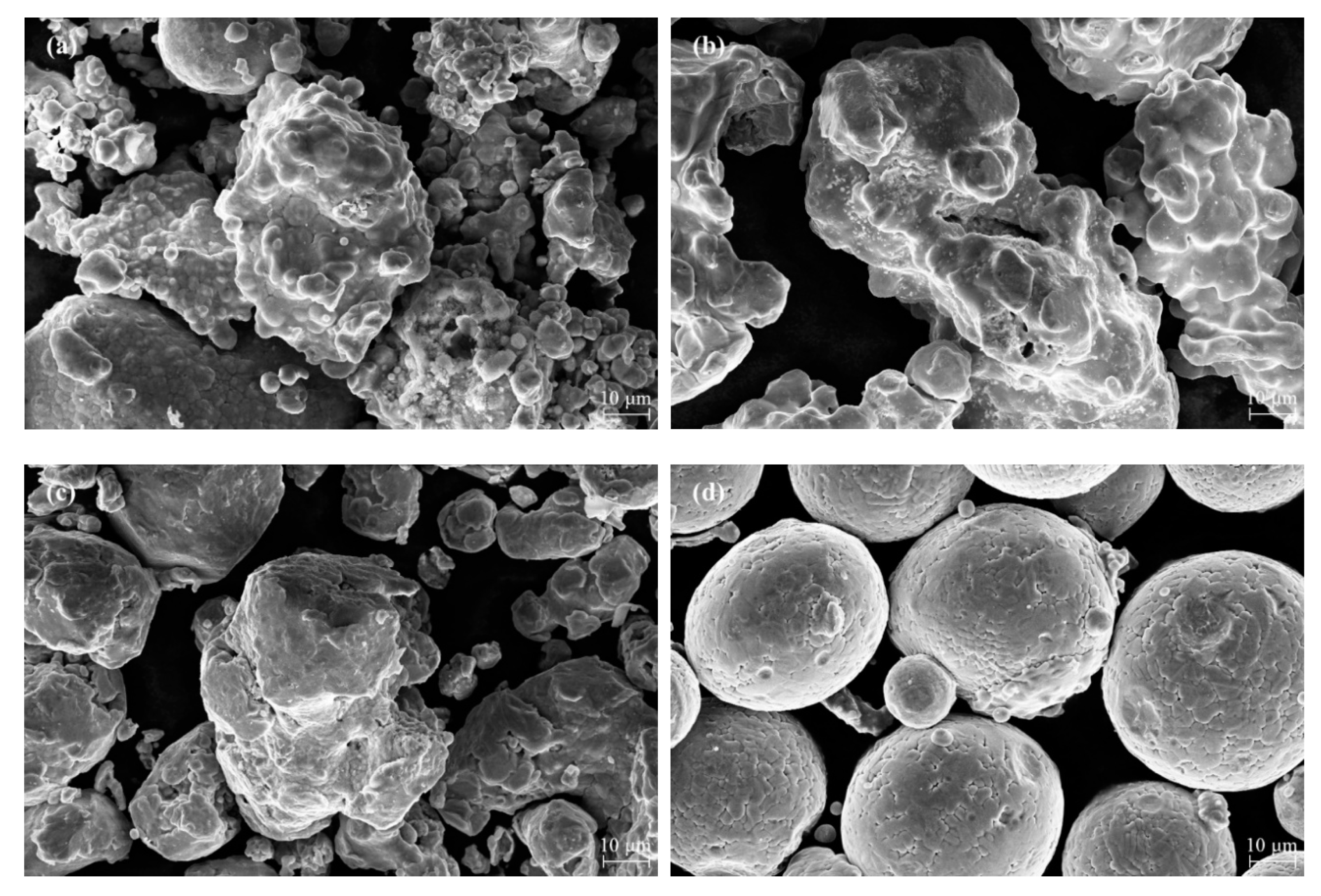
Figure 1 displays representative SEM images of the steel powder particles atomised according to the different routes. It can be observed that WA powders feature an irregular morphology compared to the spherical-shaped GA powder. This is due to the high solidification rate induced by the water spray, estimated to be 10 to 100 times higher than that induced by gas atomizing jets, which does not allow a full redistribution of the surface tension field to reproduce the equilibrium spherical geometry [29]. It is also observed that the irregular WA powder morphology can be significantly improved by the post-atomisation treatment, which mainly acts by smoothing the powder particle surfaces and by removing the largest satellites.
The data about powder properties collected in Table 3 show that the Hall flow rate is significantly affected by the atomisation process, improving from 28–36 s to 12 s when moving from WA to GA steels. The effectiveness of the post-atomisation treatment on the WA powders is confirmed by the flowability data that are close to those of GA powders. Apparent and tapped density measurements provide further indication about the ability of GA and post treated WA powders to be easily spread into dense beds during L-PBF processing.
3.2. Microstructure Evolution
3.2.1. Relative Density
Data about the relative density achieved after L-PBF processing according to optimised parameters for each of the steel investigated are also provided in Table 3. It is observed that the WA steels could attain a fairly good density, which is strictly related to the powder properties such as flowability and apparent and tapped density. The application of a post treatment on W-type powder resulted in a further improvement of the achievable density after L-PBF, with values exceeding 99.5% achieved in WT-type steels processed under optimal conditions. As expected, G-type steels could also be densified to values as high as 99.9%.
3.2.2. Nonmetallic Inclusions
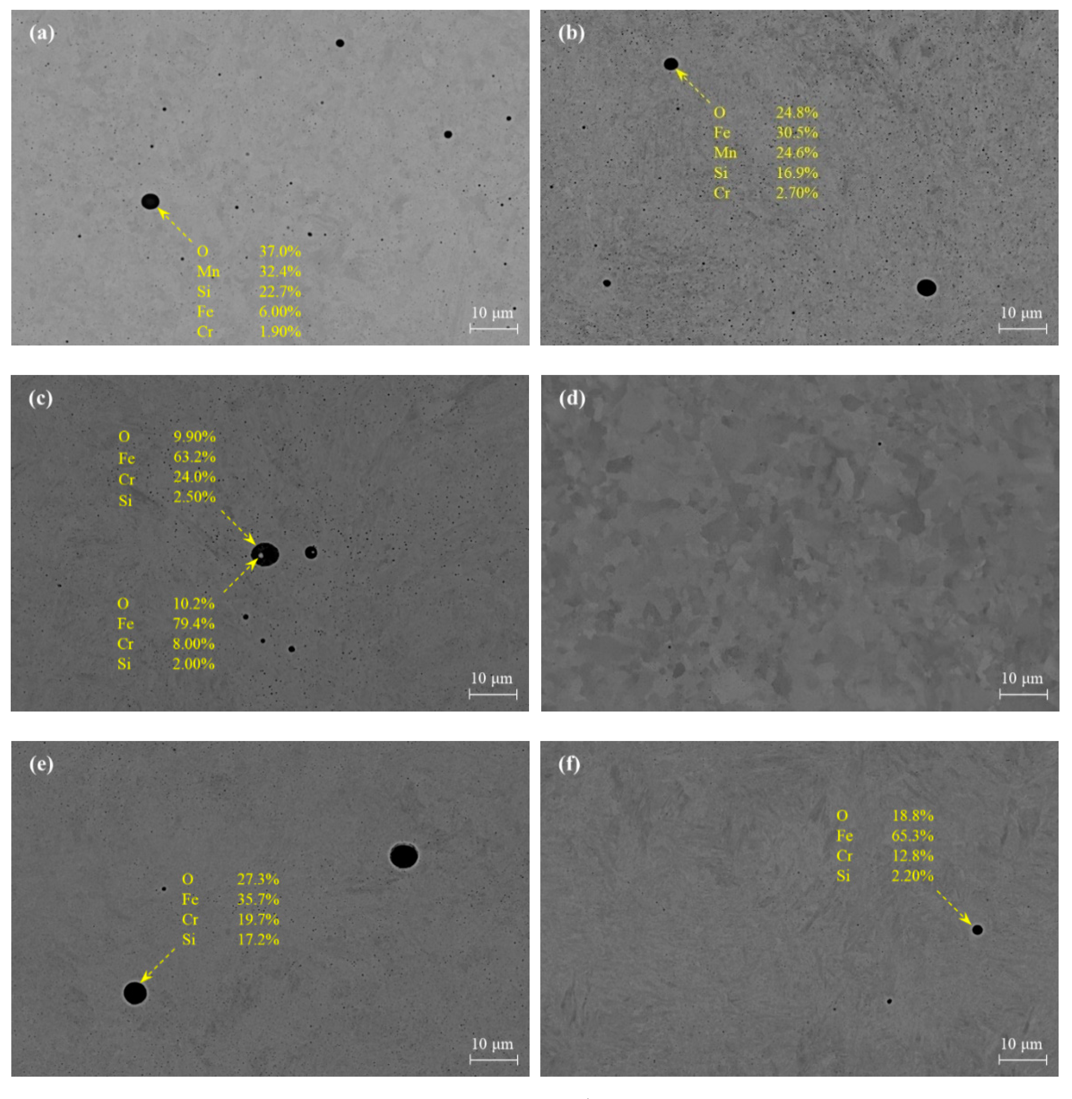
The nature of the WA process results in a significant oxygen pickup that reflects in the composition of the powder (see Table 1). Upon L-PBF processing, the formation of oxide inclusions is therefore promoted in the microstructure. FE-SEM micrographs of the investigated alloys in as-built condition and EDS elemental maps are displayed in Figure 2 and Figure 3, respectively to confirm this statement.
Oxides of the type MnO-SiO2 having a maximum diameter of about 4 μm were observed on the polished surfaces of W-1 and W-2 steels. While in W-3 and WT-1 alloys containing 3.1% wt. Cr, relatively larger (around 6 μm) Cr-rich oxides, presumably of the type Cr2O3, were detected. In addition, Fe-rich particles were often found embedded in the Cr2O3 oxides leading to more complex multi-phase inclusions, as shown in Figure 3c. Single phase SiO2 inclusions were detected in the low-Mn and 0.82% Cr WT-2 steel, with a size up to about 2 μm, as depicted in Figure 2f. The results are in agreement with the paper published by Shibata et.al. [30] who confirmed that Cr2O3 coexists with other oxides of type MnO-SiO2 in 5% Cr steels while only MnO-SiO2 are observed in steels containing less than 1% Cr.
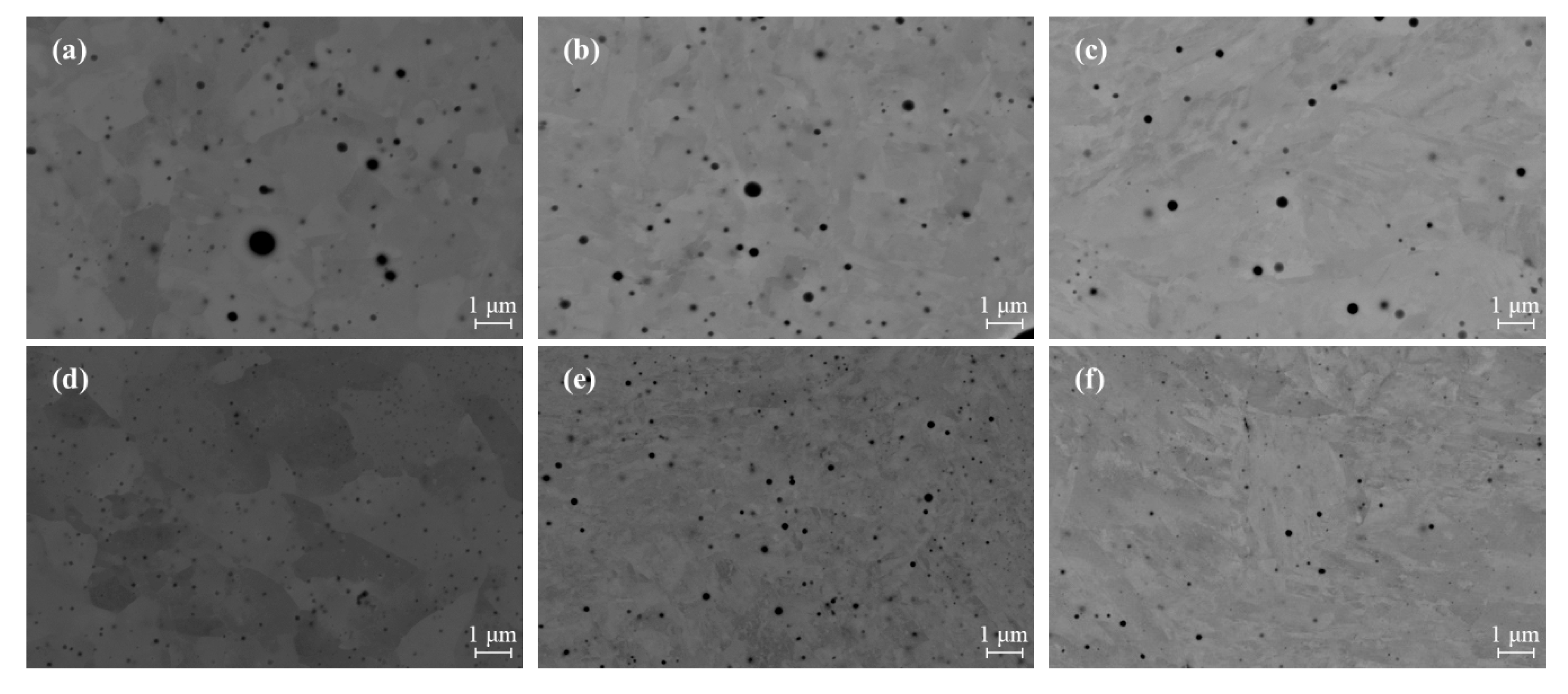
Although W-4 alloy is also rich in Cr, no significant amount of inclusions was detected in the matrix owing to the post-atomisation oxygen-reduction treatment that lowers the oxygen content down to 0.159%. Higher magnification FE-SEM micrographs are collected in Figure 4 to highlight the distribution of nano-inclusions found in the investigated steels. It is readily observed that less-frequent oxides were formed in W-4 alloy compared to the other steels, confirming that the oxide inclusions are mainly dependent on the steel chemistry, in particular on the amount of oxide-former elements and oxygen content.
It is finally assumed that the dependency of achievable density of samples on oxygen content (hence on inclusion faction and size) of steel is only of indirect nature, it being mainly dependent on the powder properties (flowability and apparent/tapped densities).
3.2.3. As-Built Microstructure
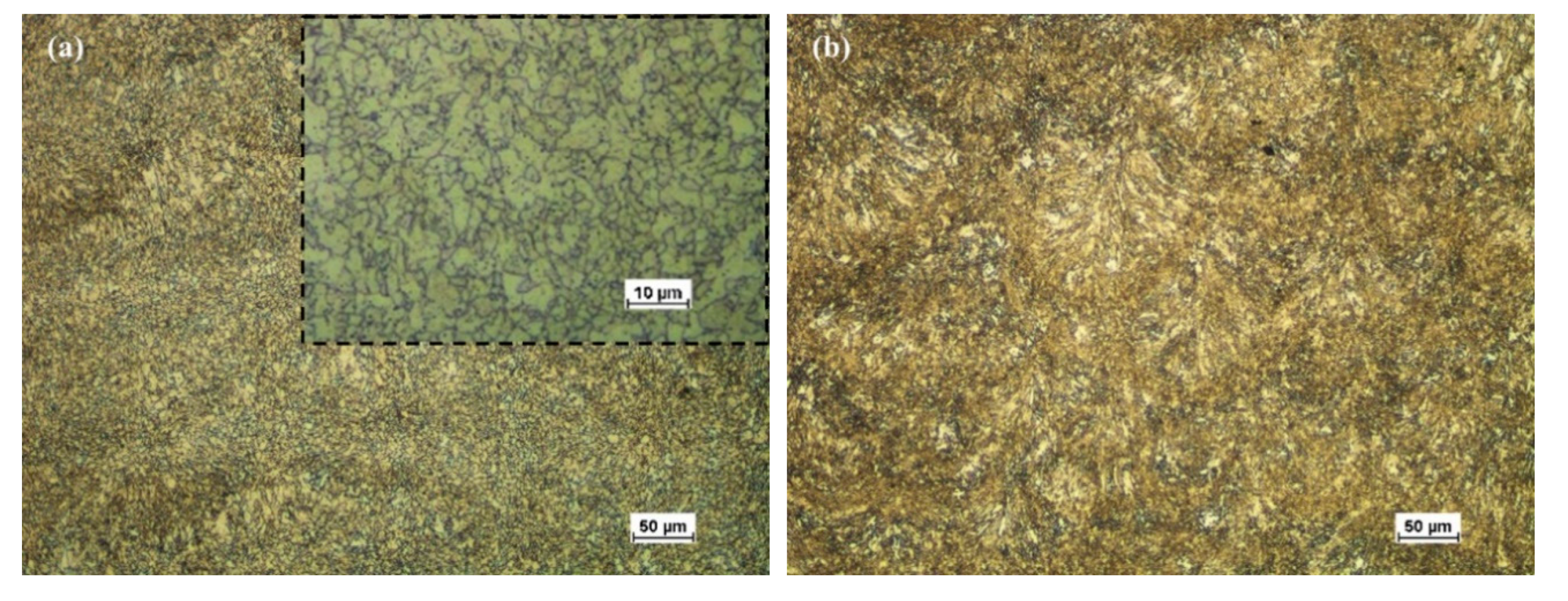
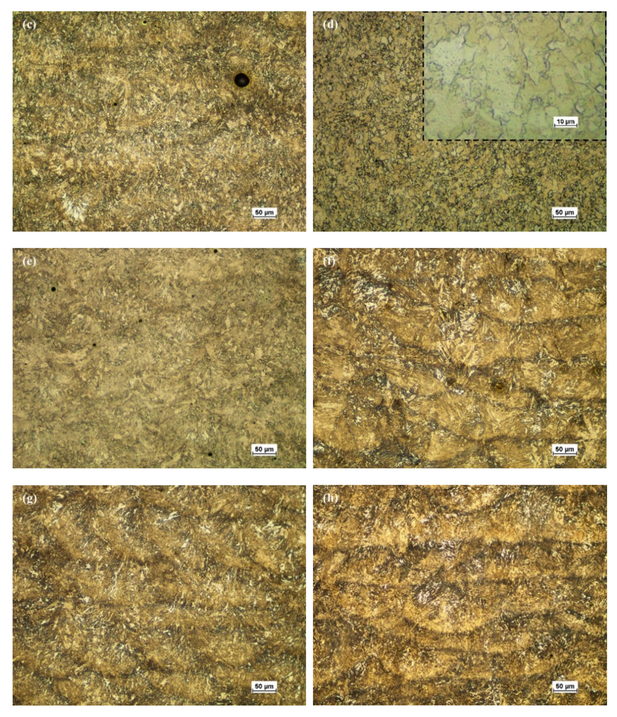
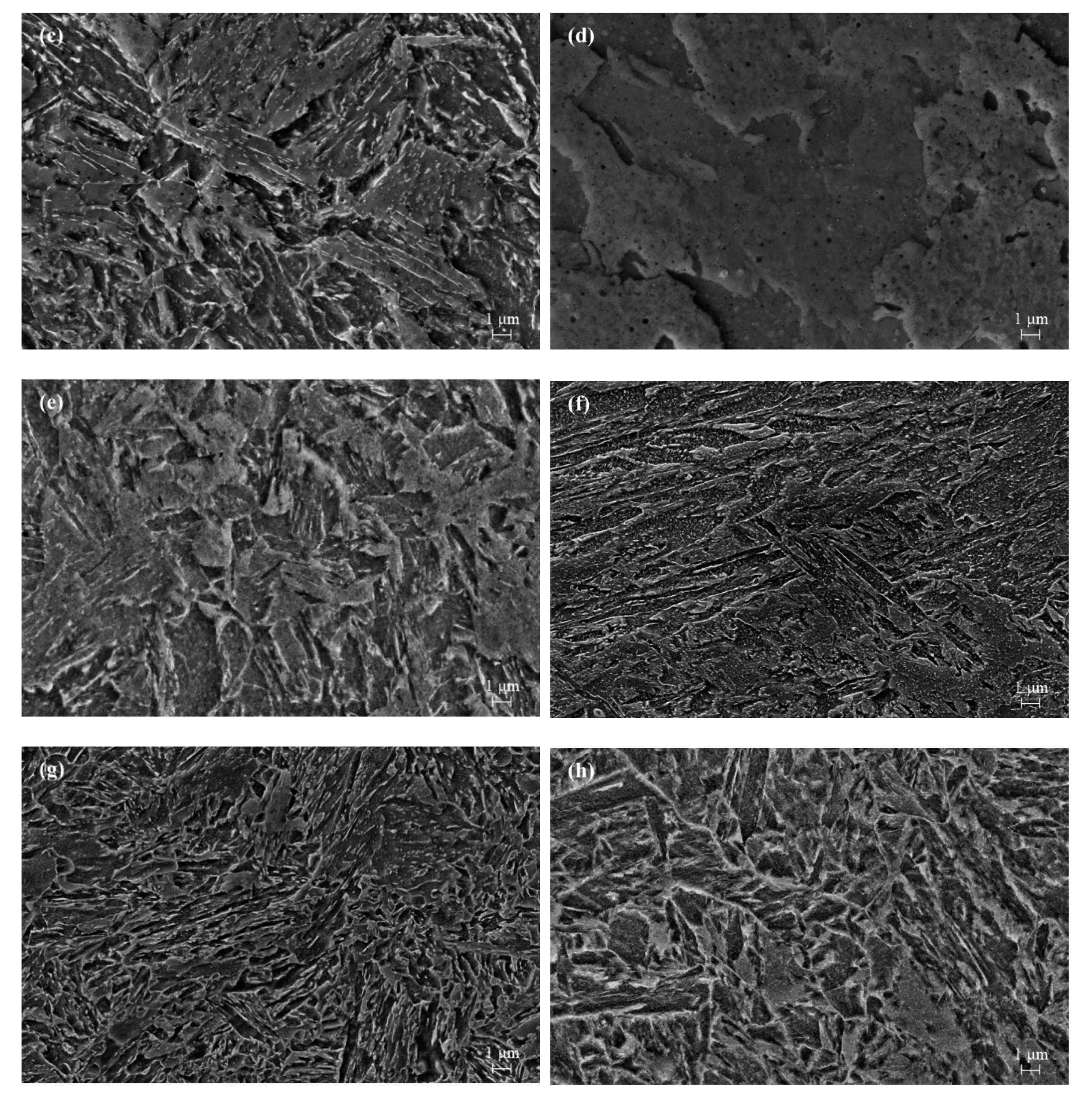
Optical and high magnification SEM micrographs of the investigated steels in as-built condition are reported in Figure 5 and Figure 6, respectively. Typical features of the layer-by-layer laser melting process are inferable in most of the micrographs given in Figure 5. The melt pools resulting from laser scanning tracks are revealed by the different etching effect induced in those steels containing significant amount of carbon. On the contrary, in W-1 and W-4 alloys, containing 0.05 and 0.005% C, respectively, a fairly homogeneous structure is revealed, in which ferrite grains are dominant as indicated in Figure 5a,d.
Based on the chemical compositions given in Table 1 and on the microstructures reported in Figure 5 and Figure 6, it is possible to divide the investigated steels into three groups. W-1 and W-4 are low and ultra-low C-steels featuring very low ability to be hardened upon rapid cooling. The Ni-containing W-2, WT-2 and G-2 steels, also alloyed with Cr and Mo, with 0.12%, 0.32% and 0.37% C, respectively, are expected to show increasing hardenability. Indeed, WT-2, and G-2 steels are designed as quench and tempering steels. Finally, the 0.15% C W-3/WT-1 and G-1 grades, containing 3.1% and 1.27% Cr, respectively, with variable amounts of Mo, correspond to case-hardening or low-C quench and tempering steels.
As already mentioned, the structure of W-1 and W-4 steels is substantially made up of the α-Fe phase. In the W-4 alloy, ferritic grains with fairly homogeneous size in the range 5–10 μm are observed (Figure 6d) whereas in the W-1 steel, a mixture of finer equiaxed and acicular ferrite is noticed (Figure 6a). The refinement and modification of the microstructure is supposed to be mainly related to the higher oxide inclusion content in this latter alloy that promotes pinning effects on the grain boundaries and suppresses the prior austenite grain growth [31,32].
W-3 and WT-1 as its post-treated counterpart, together with G-1 alloy feature a combination of (upper) bainite and of tempered martensite. It is assumed that the moderate hardenability of these steels does not allow reaching a fully martensitic structure upon rapid cooling from solidification temperature. It is also worth mentioning that tempering effects on the fresh martensite formed upon rapid cooling from solidification are induced by the heat flow from the adjacent laser tracks and from the overlapped molten layers.
Finally, W-2, WT-2 and G-2 steels result after L-PBF processing in an almost fully martensitic structure. Specifically, in the W-2 specimen a small fraction of ferrite grains can be observed, whereas in the WT-2 and G-2 grades, featuring a higher C content, only tempered martensite is observed. The finer morphology of WT-2 compared to G-2 steel could presumably be accounted for by the refining effect of Si and the higher oxide content in the former steel.
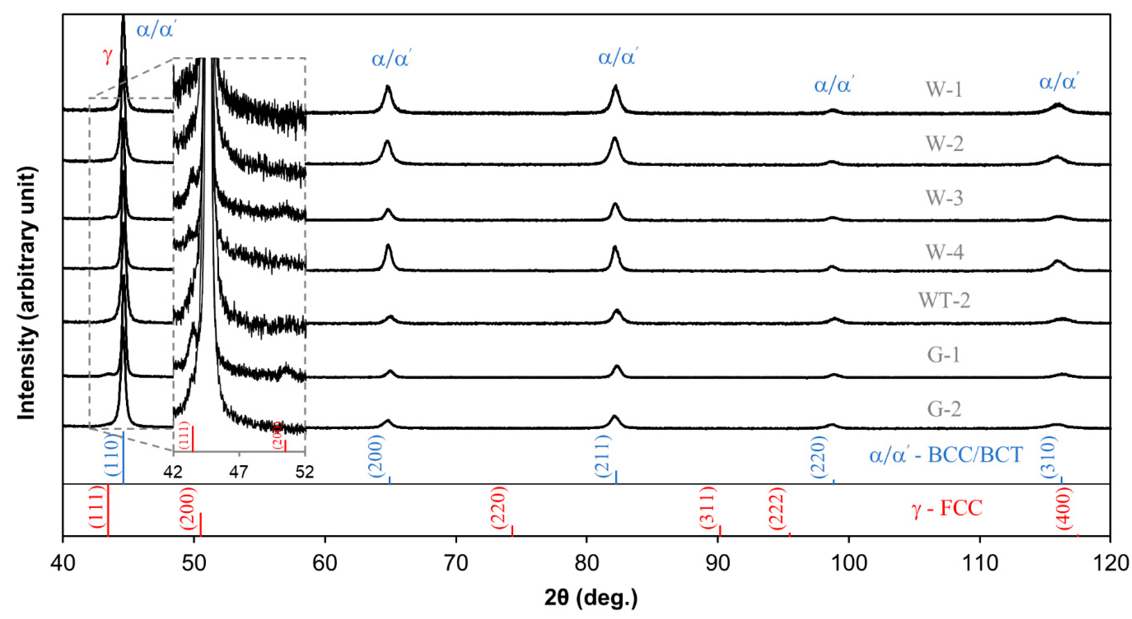
XRD spectra collected on the as build steels are displayed in Figure 7. The peaks corresponding to the main α or α’ phases can be easily recognised, while additional smaller peaks of the γ-phase can be distinguished from background signal in the magnified inset of the figure in some steels, namely W-3 and G-1 and, to a lower extent, in WT-2 and G-2 steels.
3.3. Thermal Analysis and Phase Modelling
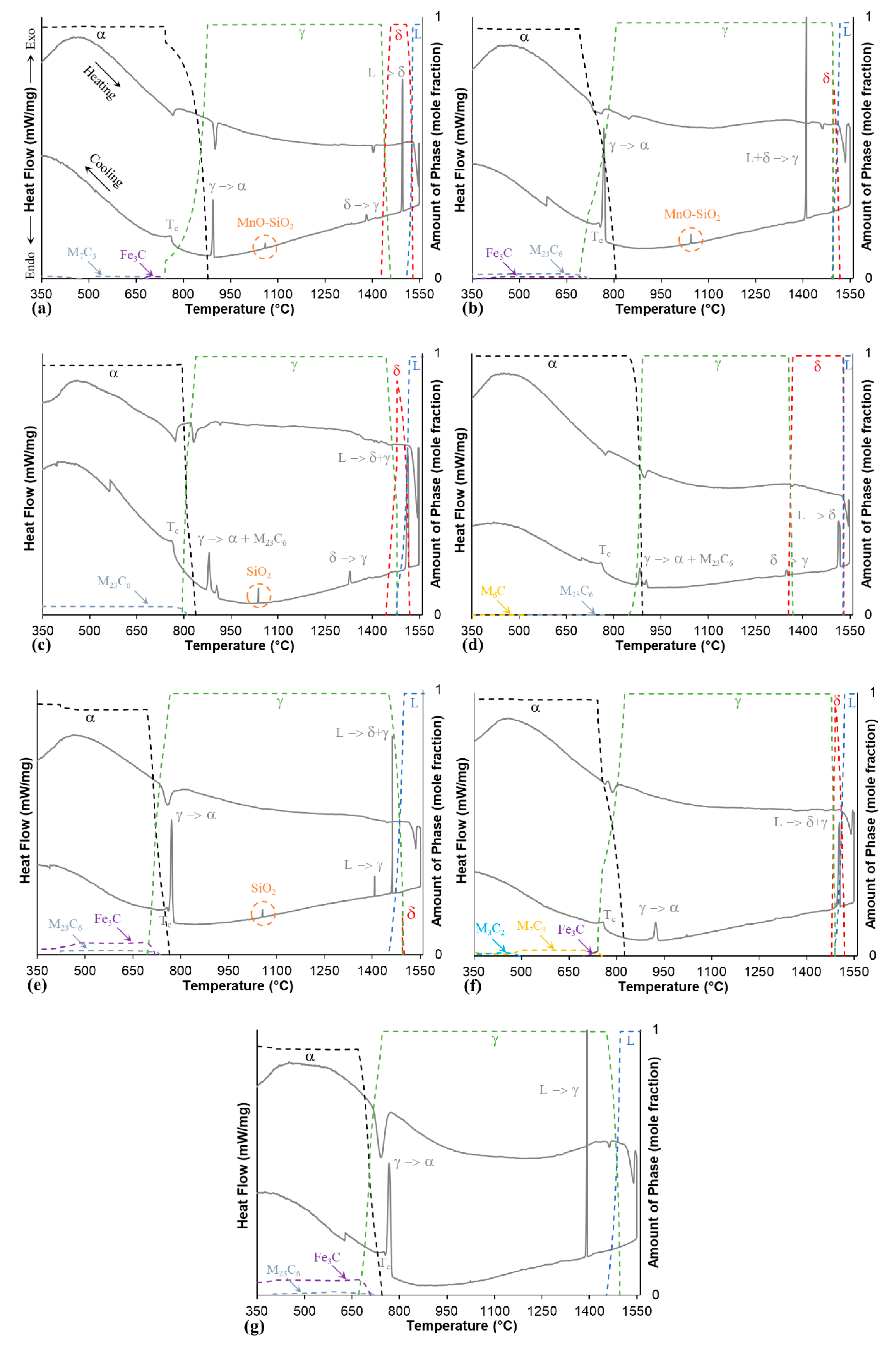
Phase transformations were studied by DSC tests with the support of thermodynamic simulations. In the diagrams of Figure 8, the heat flow curves (solid lines) obtained from the DSC tests are plotted. In the same figure, dashed lines are reported showing the volume fractions of expected phases as a function of temperature, as obtained by thermodynamic phase stability calculations based on equilibrium hypothesis. Additionally, the solidification ranges and the main transformation temperatures estimated by both methods are collected in Table 4.
It is readily observed from such graphs that the investigated steels experience different solidification modes and transformation temperatures depending on their chemical composition. W-1 and W-4 alloys feature low C contents and consistently they show a solidification sequence: liquid → δ-Fe followed by solid state transformation into γ-Fe. On the contrary, Steels W-2, W-3, WT-2 and G-1 display a peritectic solidification mode involving the sequence: liquid → liquid + δ-Fe → δ-Fe + γ-Fe followed by solid state transformation into γ-Fe. Finally, G-2 steel features the direct solidification into austenite according to the sequence: liquid → γ-Fe.
Solid state transformations will be here discussed considering mainly the cooling behaviour of the DSC plots (lower curves in Figure 8) that allow understanding the occurrence and position of the phase transformation when the steels are cooled at a fairly low rate (10 °C/min), whereas the heating branch of the DSC tracks can be referred to transformations on heating, starting from steels that had been rapidly cooled down to room temperature (L-PBF processed). The γ-Fe → α-Fe transformation can clearly be identified in all of the cooling curves, while an eutectoid reaction of γ-Fe → α-Fe + M23C6 (presumably Cr-type carbide) is noticed in the 3.1% Cr alloys, namely in W-3 and to a lower extent in W-4 specimen, as shown in Figure 8c,d respectively.
Other secondary peaks found at 1060, 1045, 1038 and 1056 °C can be noted on the cooling DSC curves in steels W-1, W-2, W-3 and WT-2 respectively. The listed alloys correspond to the WA powders which are rich in oxygen as a result of the atomisation process itself. According to the thermodynamic calculations, these signals are supposed to be related to oxide precipitation of the type MnO-SiO2 in W-1 and W-2 alloys, and single phase SiO2 in W-3/WT-1 and WT-2. It is noteworthy to mention that the mixed Cr2O3-SiO2 oxide could in principle also exist in W-3/WT-1 steels at higher oxygen levels. Additionally, EDS analysis maps previously discussed in Figure 3 confirm the presence of such oxides in as-built condition. From literature it was demonstrated that oxides can be subjected to phase changes within a steel matrix during isothermal treatments at 900–1400 °C [31,32,33,34].
Carbide precipitation is also expected from phase stability simulation, especially in steels with the higher C and Cr contents (WT-2 and G-2 alloys). Specific peaks for these precipitates are not observed in the DSC curves since the precipitation is expected to occur over a wide temperature range. Finally, changes in ferromagnetic properties of the steel alloys i.e., the curie temperature (Tc) can be clearly defined as sharp steps in some of the DSC cooling profiles [35].
3.4. Thermal Treatment Strategies
Two different heat treatment routes have been evaluated. The conventional quench and tempering schedules have been taken as the reference hardening treatment, to be composed by an austenitising stage carried out above AC3, followed by a water quench and a tempering stage. A second option was devised by simply tempering the steels directly after the laser processing.
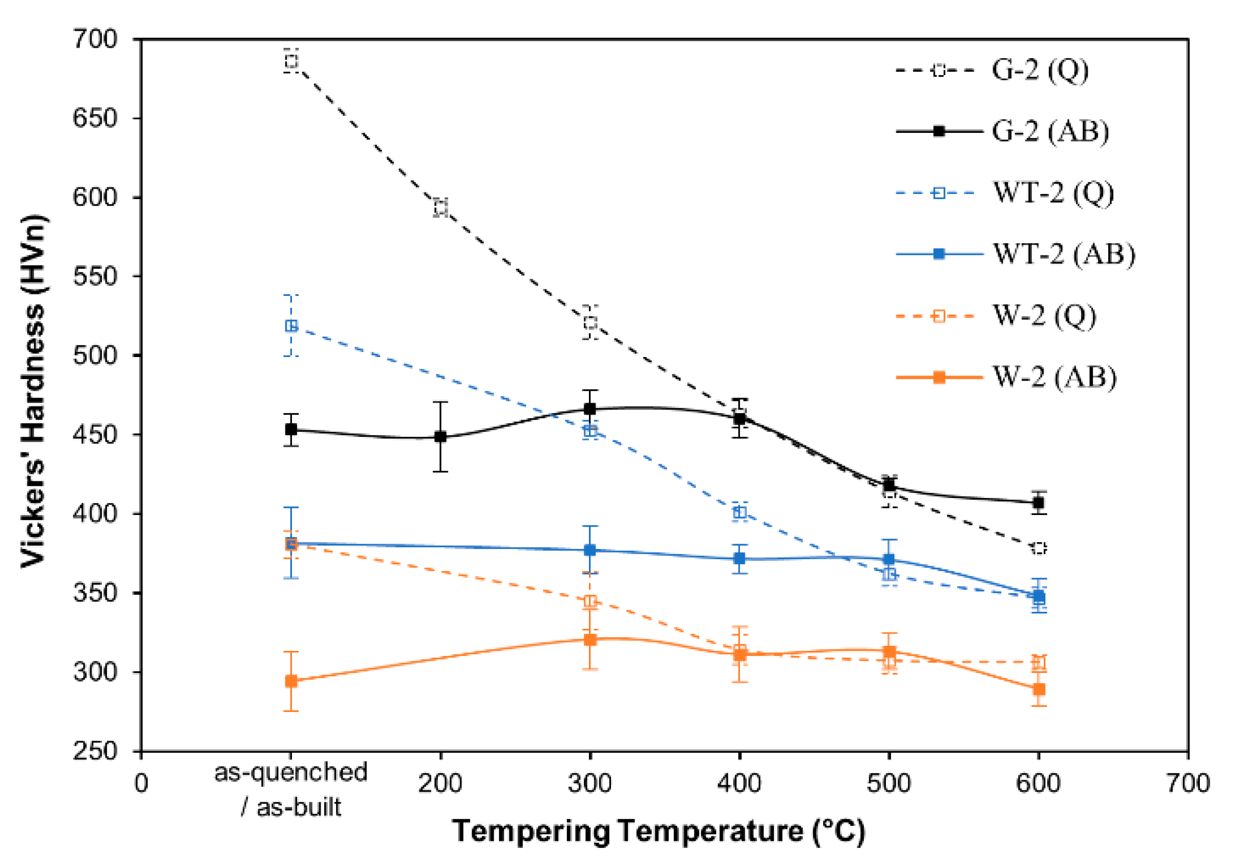
As already mentioned, it is considered that the most hardenable steels investigated can at least partially transform into martensite on cooling after laser melting. The following adjacent laser tracks and the overlapping of several other layers additionally produce a reheating effect (according to complex and variable combinations of heating temperatures and times) then results in a partial in situ tempering. Figure 9 depicts the hardness evolution during tempering of some of the investigated steels, according to the two selected treatment schedules.
The traditional tempering curves of the quenched steels (dashed lines) show the expected decreasing trend with increasing tempering temperature, with hardness values that are obviously affected by the carbon content and by the amount of alloying elements. On the contrary, the analysis of the tempering behaviour starting from as-built specimens shows limited variations in hardness, suggesting that the reheating cycles experienced by the materials during L-PBF processing already resulted in a tempered structure that can be compared to a conventional tempering performed at about 400–450 °C after quenching. Considering this aspect, the direct use of some of the investigated steels in the as-built condition could be considered as a feasible alternative. This option is also confirmed by Wang and Kelly [11], who measured a comparable or even higher mechanical performance for an L-PBF-processed 4140 steel over its wrought counterpart.
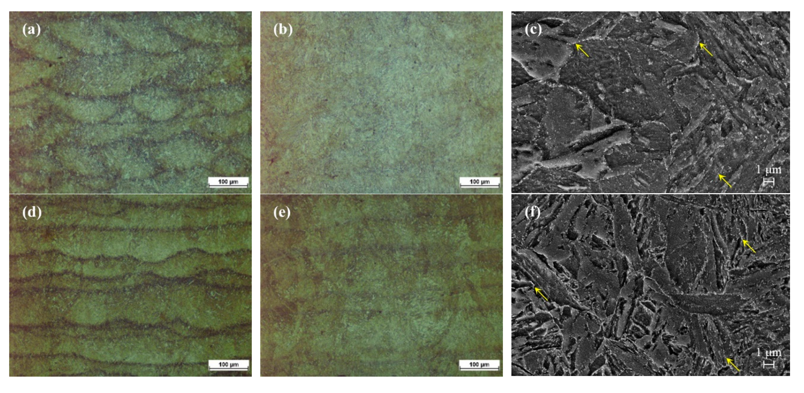
The evolution of microstructure after tempering for one hour at selected temperature levels (200, 400 and 600 °C) starting from the as-built condition is summarised in the micrographs given in Figure 10 for G-1 and G-2 steels. For both alloys, no significant changes in the microstructure and hardness values compared to the as-built condition were observed after tempering at 200 °C. The contours of the distinct melting pools tend to vanish at 400 °C, while tempering at 600 °C resulted in the precipitation of dispersed carbides mainly decorating the boundaries of the martensite laths, Figure 10c,f. The thermodynamic simulations suggested that, at such condition, the stable carbides are Cr7C3 and Fe3C for G-1 and G-2 steels, respectively. Their formation is supposed to be linked to the decomposition of retained austenite and to the dissolution of transition carbides [36,37].
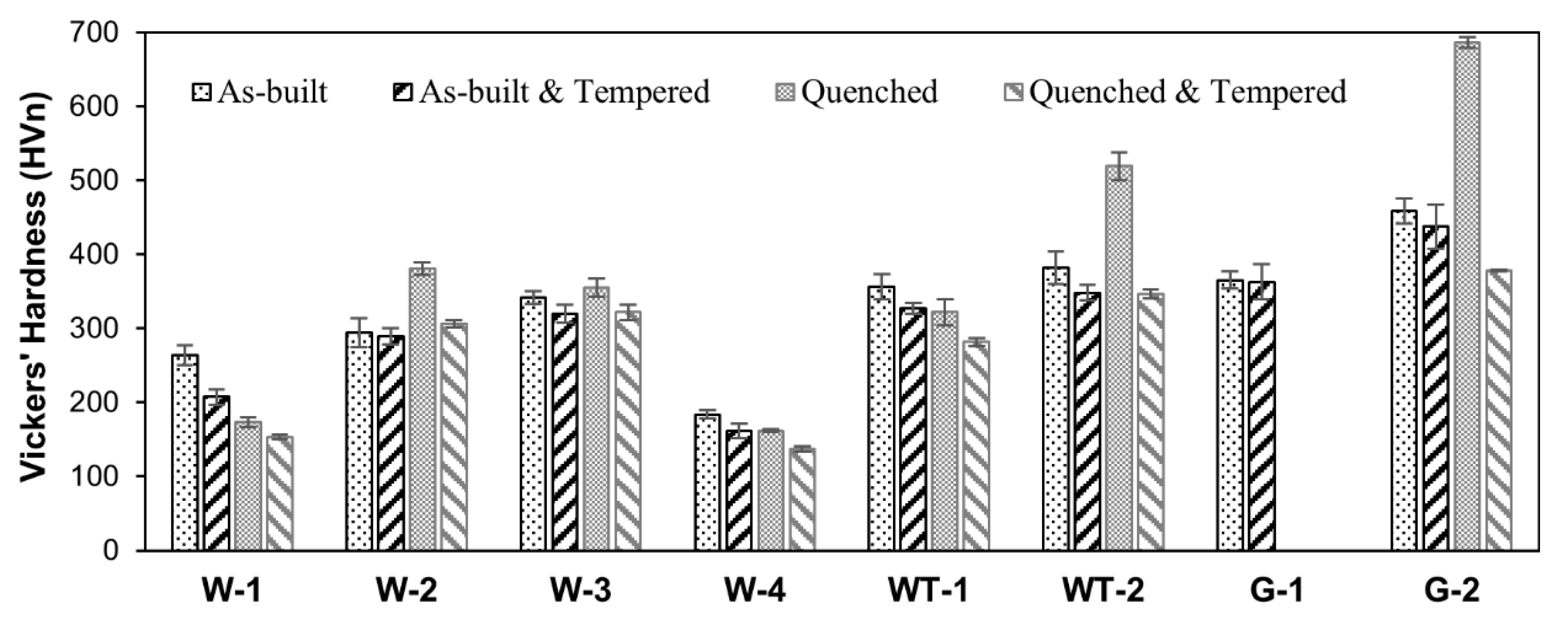
A summary of the Vickers’ hardness achieved after the different heat treatment schedules is reported in Table 5 and presented in graphical form in Figure 11. Considering the as-built state of the investigated steels, it can be observed that hardness could be increased from 184 HV up to 459 HV by increasing the carbon content as well as the amount of alloying elements. Moreover, the results showed that only the low carbon alloys W-1 and W-4 experienced a significant loss in hardness after direct tempering/stress relieving at 600 °C, while the remaining set of steels could show a limited hardness loss compared to the as-built condition.
As expected, a specific quenching for the low carbon alloys W-1 and W-4 is not beneficial to improve the hardness over the as-built specimens. On the contrary, the more alloyed steels improved their hardness after deliberate quenching. It is finally worth noting that the hardness levels achieved after tempering, either from as-built condition or from quenching, are substantially comparable with the exception of G-2 steel.
3.5. Tensile Properties
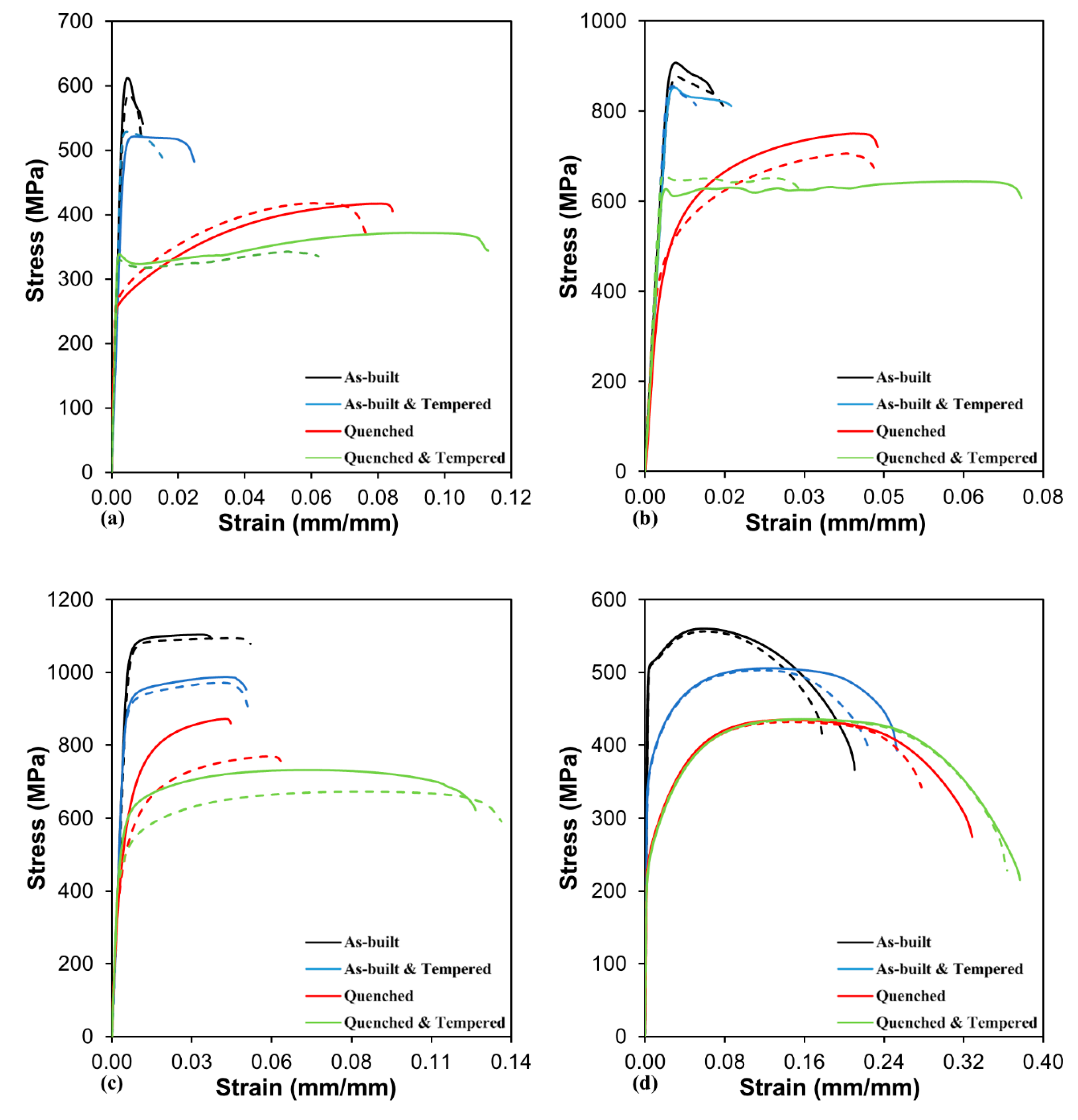
Tensile tests have been performed on the WA-series steels in the as-built condition and after thermal treatments considering a fixed tempering temperature of 600 °C for all the steels. The collected tensile curves and the main tensile data are reported in Figure 12 and in Table 6, respectively.
The tensile data about this set of WA steels systematically show that tensile strength follows a precise trend among the different investigated conditions. The ranking, from the highest to the lowest UTS is: AB, AB + T, Q, Q + T. As expected, the fracture elongation values follow an opposite trend, Q+T being the condition that allows achieving the highest ductility. The above mentioned trend is also consistent with the observed constituents in the steels, whereby the highest to lowest UTS levels correspond to martensitic W-3, dual phase W-2, fine grain ferritic W-1, and relatively coarse grain ferritic W-4 steels.
Regarding the W-1 and W-4 ferritic steels in all the investigated conditions, higher ductility was observed for W-4 steel featuring a relative density of 99.9% compared to W-1 steel with a density of 97.8%.
3.6. Fractographic Analysis
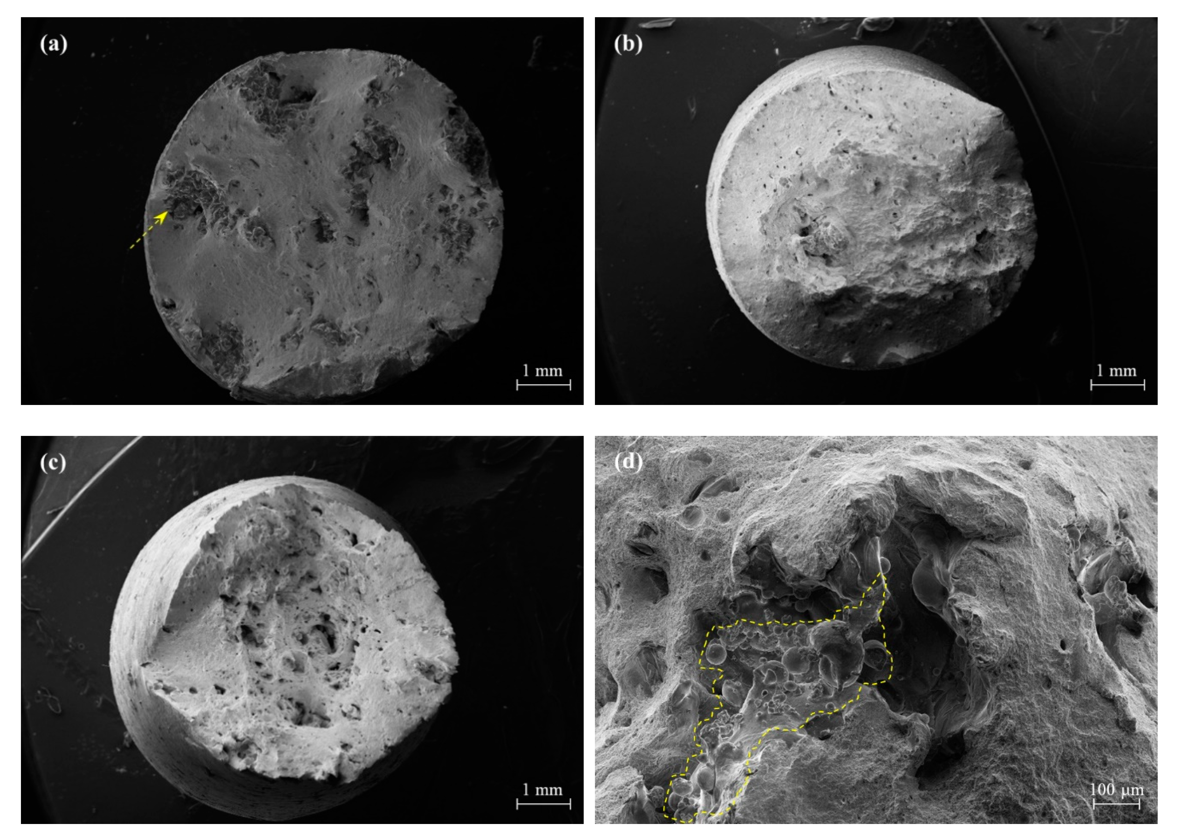
A summary of the fracture aspect of the broken WA steel specimens in as-built and thermal-treated conditions is displayed in Figure 13, while higher magnification views of the fracture surfaces are given in Figure 14. All the specimens showed a macroscopically ductile failure mode. The general views of the specimens highlight the presence of rough areas (arrowed in Figure 13a) associated to pre-existing lack of fusion defects generated during the L-PBF process. Figure 13d shows the detail of such a defect in a limited area, on which un-melted powder particles can be recognised.
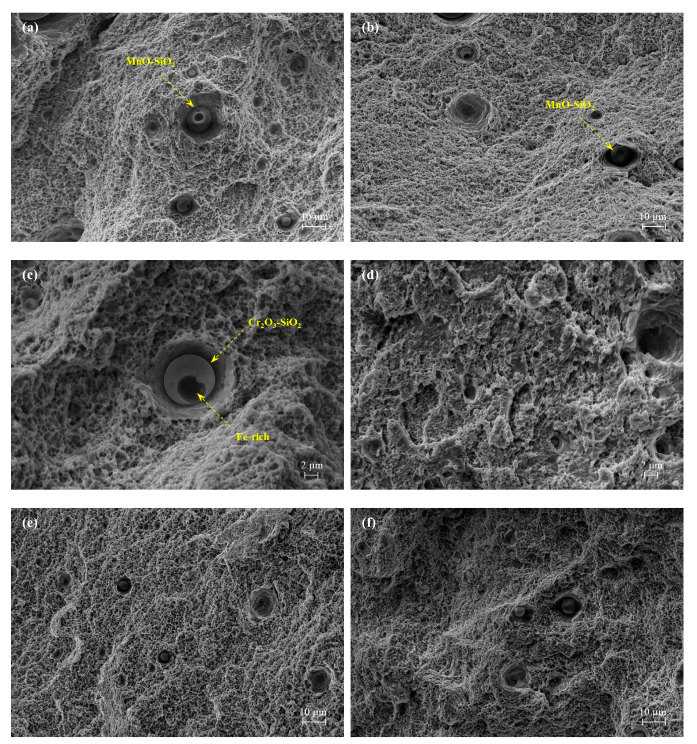
Higher magnification views of the surface area corresponding to crack development in defect-free regions reveal the growth of micro-dimples in the ductile steel matrix, generally originated from inclusions. In W-1 and W-2 alloys, Figure 14a,b respectively, spherical MnO-SiO2 oxides acted as nucleation sites for the dimples. In accordance to the bimodal size distribution of the oxide inclusions, few larger dimples nucleated from relatively coarse inclusions, whereas a much wider population of smaller pores supposedly grew from the sub-micrometre size inclusions. In Figure 14c, the complex multi-phase inclusion of Fe-rich particle enveloped by Cr-oxide was again observed in W-3 alloy. Finally, glassy fragmented Mn-rich and Cr-rich intermetallic compounds were occasionally detected on the fracture surfaces of W-1/W-2 and W-3/W-4 alloys, respectively.
4. Concluding Remarks
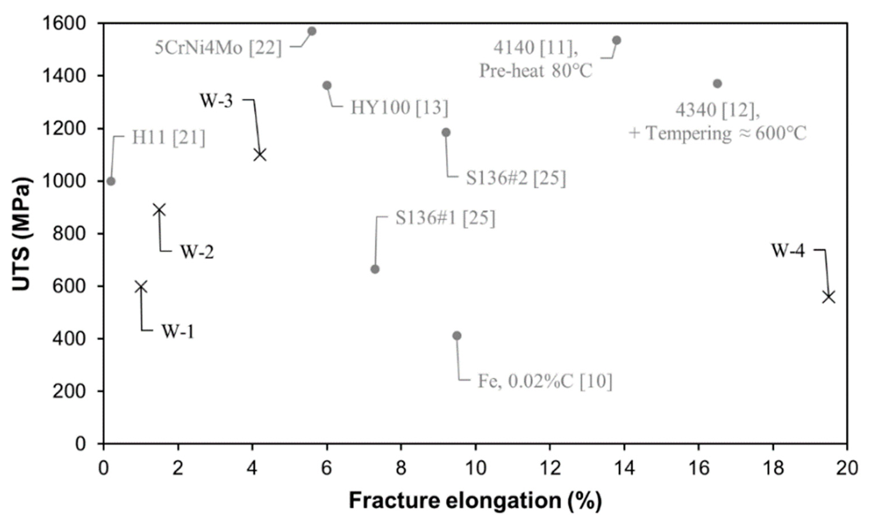
The mechanical properties of the investigated as-built W-series alloys along with other L-PBF processed structural and tool steels available in the literature [10,11,12,13,21,22,25] have been collected in Figure 15 with the aim of drawing a scenario about available steels and related properties for L-PBF. It can be observed that the investigated water-atomised alloys show mechanical performances that can potentially fill some existing gaps on the map of available steel properties, offering several opportunities grades with strength rather than improved ductility depending on their composition and temper. Apparently, the water atomisation process does not result in any depletion of properties when compared to other gas-atomised steels reported in the map. In addition, it is to consider that tuning the steel temper by proper thermal treatments would supply further combinations of properties that could profitably widen the range of structural steels to be considered for AM part design.
In summary, the described investigation carried out on a range of structural low-alloy steels, allowed to draw the following conclusions.
- Production of steel powders by water atomisation, possibly followed by a post-treatment aimed at modifying powder morphology and its flowability, can lead to suitable feedstock materials for L-PBF. Indeed, despite a more irregular morphology of the water-atomised powders, after an accurate setting of the parameters for the powder bed deposition and for the laser melting, specimens having a density exceeding 99.5% could be produced.
- Depending on steel composition and microstructure achieved after the rapid solidification and cooling upon L-PBF processing, hardness values ranging from 182 up to 490 HV were achieved in the investigated steels in as-built condition.
- The hardenable steels, containing suitable amounts of C and of alloying elements (Cr, Mn, Mo, Ni), could benefit from post-processing quench and tempering heat treatments to achieve improved combination of properties. It was also demonstrated that the cooling and reheating cycles experienced by the steels during L-PBF processing resulted in a condition which is comparable to a tempering treatment performed around 400 °C.
- The low C W-1 and W-4 alloys showed a more homogeneous microstructure consisting of ferrite grains that provided their highest strength right in the as-built condition.
- The WA steel grades featured a higher oxygen content which resulted in a population of small micrometre- and submicrometric-size oxide inclusions. Their presence was detected on fracture surface of broken tensile specimens as nucleating sites for micro-dimples activating a ductile fracture mechanism.
Author Contributions
M.A.: conceptualisation, methodology, software, validation, formal analysis, investigation, data curation, visualization, and writing—original draft; R.C.: conceptualisation, methodology, investigation, and writing—review and editing; S.B.: investigation and resources; A.L.: investigation, resources, and writing—review and editing; M.R.: investigation and resources; M.V.: conceptualisation, methodology, validation, investigation, resources, writing—review and editing, supervision, and funding acquisition. All authors have read and agreed to the published version of the manuscript.
Funding
The present investigation was carried out in the frame of the joint research project SPAcEMAN—Sustainable Powders for AdditivE MANufacturing, funded by EIT-Raw Materials in 2018–2021. The Italian Ministry of Education, University and Research is also acknowledged for the support provided through the project “Department of Excellence LIS4.0—Lightweight and Smart Structures for Industry 4.0”. M.A. acknowledges the Egyptian Ministry of Higher Education and Scientific Research, sector of Cultural Affairs and Missions for financial support of his Ph.D. grant.
Acknowledgments
M.A. would finally like to thank Francesca Villa for her assistance with experimental tests and Ludovica Rovatti for her technical support at Politecnico di Milano.
Conflicts of Interest
The authors declare no conflict of interest.
References
- DebRoy, T.; Wei, H.L.; Zuback, J.S.; Mukherjee, T.; Elmer, J.W.; Milewski, J.O.; Beese, A.M.; Wilson-Heid, A.; De, A.; Zhang, W. Additive manufacturing of metallic components—Process, structure and properties. Prog. Mater. Sci. 2018, 92, 112–224. [Google Scholar] [CrossRef]
- Sames, W.J.; List, F.A.; Pannala, S.; Dehoff, R.R.; Babu, S.S. The metallurgy and processing science of metal additive manufacturing. Int. Mater. Rev. 2016, 61, 315–360. [Google Scholar] [CrossRef]
- Heiden, M.J.; Deibler, L.A.; Rodelas, J.M.; Koepke, J.R.; Tung, D.J.; Saiz, D.J.; Jared, B.H. Evolution of 316L stainless steel feedstock due to laser powder bed fusion process. Addit. Manuf. 2019, 25, 84–103. [Google Scholar] [CrossRef]
- Casati, R.; Lemke, J.; Vedani, M. Microstructure and Fracture Behavior of 316L Austenitic Stainless Steel Produced by Selective Laser Melting. J. Mater. Sci. Technol. 2016, 32, 738–744. [Google Scholar] [CrossRef]
- Zhang, B.; Dembinski, L.; Coddet, C. The study of the laser parameters and environment variables effect on mechanical properties of high compact parts elaborated by selective laser melting 316L powder. Mater. Sci. Eng. A 2013, 584, 21–31. [Google Scholar] [CrossRef]
- LeBrun, T.; Nakamoto, T.; Horikawa, K.; Kobayashi, H. Effect of retained austenite on subsequent thermal processing and resultant mechanical properties of selective laser melted 17–4 PH stainless steel. Mater. Des. 2015, 81, 44–53. [Google Scholar] [CrossRef]
- Irrinki, H.; Jangam, J.S.D.; Pasebani, S.; Badwe, S.; Stitzel, J.; Kate, K.; Gulsoy, O.; Atre, S.V. Effects of particle characteristics on the microstructure and mechanical properties of 17-4 PH stainless steel fabricated by laser-powder bed fusion. Powder Technol. 2018, 331, 192–203. [Google Scholar] [CrossRef]
- Casalino, G.; Campanelli, S.L.; Contuzzi, N.; Ludovico, A.D. Experimental investigation and statistical optimisation of the selective laser melting process of a maraging steel. Opt. Laser Technol. 2015, 65, 151–158. [Google Scholar] [CrossRef]
- Casati, R.; Lemke, J.; Tuissi, A.; Vedani, M. Aging Behaviour and Mechanical Performance of 18-Ni 300 Steel Processed by Selective Laser Melting. Metals 2016, 6, 218. [Google Scholar] [CrossRef]
- Song, B.; Dong, S.; Deng, S.; Liao, H.; Coddet, C. Microstructure and tensile properties of iron parts fabricated by selective laser melting. Opt. Laser Technol. 2014, 56, 451–460. [Google Scholar] [CrossRef]
- Wang, W.; Kelly, S. A Metallurgical Evaluation of the Powder-Bed Laser Additive Manufactured 4140 Steel Material. JOM 2016, 68, 869–875. [Google Scholar] [CrossRef]
- Jelis, E.; Clemente, M.; Kerwien, S.; Ravindra, N.M.; Hespos, M.R. Metallurgical and Mechanical Evaluation of 4340 Steel Produced by Direct Metal Laser Sintering. JOM 2015, 67, 582–589. [Google Scholar] [CrossRef]
- Dilip, J.J.S.; Ram, G.D.J.; Starr, T.L.; Stucker, B. Selective laser melting of HY100 steel: Process parameters, microstructure and mechanical properties. Addit. Manuf. 2017, 13, 49–60. [Google Scholar] [CrossRef]
- Casati, R.; Coduri, M.; Lecis, N.; Andrianopoli, C.; Vedani, M. Microstructure and mechanical behavior of hot-work tool steels processed by Selective Laser Melting. Mater. Charact. 2018, 137, 50–57. [Google Scholar] [CrossRef]
- Krell, J.; Röttger, A.; Geenen, K.; Theisen, W. General investigations on processing tool steel X40CrMoV5-1 with selective laser melting. J. Mater. Process. Technol. 2018, 255, 679–688. [Google Scholar] [CrossRef]
- Schmitt, M.; Schlick, G.; Seidel, C.; Reinhart, G. Examination of the processability of 16MnCr5 by means of laser powder bed fusion. Procedia CIRP 2018, 74, 76–81. [Google Scholar] [CrossRef]
- Åsberg, M.; Fredriksson, G.; Hatami, S.; Fredriksson, W.; Krakhmalev, P. Influence of post treatment on microstructure, porosity and mechanical properties of additive manufactured H13 tool steel. Mater. Sci. Eng. A 2019, 742, 584–589. [Google Scholar] [CrossRef]
- Feuerhahn, F.; Schulz, A.; Seefeld, T.; Vollertsen, F. Microstructure and Properties of Selective Laser Melted High Hardness Tool Steel. Phys. Procedia 2013, 41, 843–848. [Google Scholar] [CrossRef] [Green Version]
- Sander, J.; Hufenbach, J.; Giebeler, L.; Wendrock, H.; Kühn, U.; Eckert, J. Microstructure and properties of FeCrMoVC tool steel produced by selective laser melting. Mater. Des. 2016, 89, 335–341. [Google Scholar] [CrossRef]
- Liu, Z.H.; Zhang, D.Q.; Chua, C.K.; Leong, K.F. Crystal structure analysis of M2 high speed steel parts produced by selective laser melting. Mater. Charact. 2013, 84, 72–80. [Google Scholar] [CrossRef]
- Huber, F.; Bischof, C.; Hentschel, O.; Heberle, J.; Zettl, J.; Nagulin, K.Y.; Schmidt, M. Laser beam melting and heat-treatment of 1.2343 (AISI H11) tool steel–microstructure and mechanical properties. Mater. Sci. Eng. A 2019, 742, 109–115. [Google Scholar] [CrossRef]
- Chen, H.; Gu, D.; Dai, D.; Ma, C.; Xia, M. Microstructure and composition homogeneity, tensile property, and underlying thermal physical mechanism of selective laser melting tool steel parts. Mater. Sci. Eng. A 2017, 682, 279–289. [Google Scholar] [CrossRef]
- Rännar, L.; Glad, A.; Gustafson, C. Efficient cooling with tool inserts manufactured by electron beam melting. Rapid Prototyp. J. 2007, 13, 128–135. [Google Scholar] [CrossRef]
- Brøtan, V.; Berg, O.Å.; Sørby, K. Additive Manufacturing for Enhanced Performance of Molds. Procedia CIRP 2016, 54, 186–190. [Google Scholar] [CrossRef] [Green Version]
- Zhou, Y.; Duan, L.; Ji, X.; Wen, S.; Wei, Q.; Ye, F.; Shi, Y. Comparisons on microstructure, mechanical and corrosion resistant property of S136 mold steel processed by selective laser melting from two pre-alloy powders with trace element differences. Opt. Laser Technol. 2018, 108, 81–89. [Google Scholar] [CrossRef]
- EU Science Hub-Raw Materials Information System (RMIS). Available online: https://rmis.jrc.ec.europa.eu/?page=crm-list-2017-09abb4 (accessed on 10 October 2020).
- Pinkerton, A.J.; Li, L. Direct additive laser manufacturing using gas- and water-atomised H13 tool steel powders. Int. J. Adv. Manuf. Technol. 2005, 25, 471–479. [Google Scholar] [CrossRef]
- Li, R.; Shi, Y.; Wang, Z.; Wang, L.; Liu, J.; Jiang, W. Densification behavior of gas and water atomized 316L stainless steel powder during selective laser melting. Appl. Surf. Sci. 2010, 256, 4350–4356. [Google Scholar] [CrossRef]
- Hoeges, S.; Zwiren, A.; Schade, C. Additive manufacturing using water atomized steel powders. Met. Powder Rep. 2017, 72, 111–117. [Google Scholar] [CrossRef]
- Shibata, H.; Kimura, K.; Tanaka, T.; Kitamura, S. Mechanism of Change in Chemical Composition of Oxide Inclusions in Fe–Cr Alloys Deoxidized with Mn and Si by Heat Treatment at 1473 K. ISIJ Int. 2011, 51, 1944–1950. [Google Scholar] [CrossRef] [Green Version]
- Shibata, H.; Tanaka, T.; Kimura, K.; Kitamura, S.-Y. Composition change in oxide inclusions of stainless steel by heat treatment. Ironmak. Steelmak. 2010, 37, 522–528. [Google Scholar] [CrossRef]
- Kim, K.-H.; Kim, S.-J.; Shibata, H.; Kitamura, S. Reaction between MnO–SiO2–FeO Oxide and Fe–Mn–Si Solid Alloy during Heat Treatment. ISIJ Int. 2014, 54, 2144–2153. [Google Scholar] [CrossRef] [Green Version]
- Ren, Y.; Zhang, L.; Pistorius, P.C. Transformation of Oxide Inclusions in Type 304 Stainless Steels during Heat Treatment. Metall. Mater. Trans. B 2017, 48, 2281–2292. [Google Scholar] [CrossRef]
- Zhang, X.; Yang, S.; Li, J.; Liu, C.; Hao, W. Evolution of Interfacial Features of MnO-SiO2 Type Inclusions/Steel Matrix during Isothermal Heating at Low Temperatures. High Temp. Mater. Process. 2019, 38, 347–353. [Google Scholar] [CrossRef]
- Raju, S.; Jeya Ganesh, B.; Rai, A.K.; Mythili, R.; Saroja, S.; Raj, B. A study on martensitic phase transformation in 9Cr–1W–0.23V–0.063Ta–0.56Mn–0.09C–0.02N (wt.%) reduced activation steel using differential scanning calorimetry. J. Nucl. Mater. 2010, 405, 59–69. [Google Scholar] [CrossRef]
- Van Genderen, M.J.; Isac, M.; Böttger, A.; Mittemeijer, E.J. Aging and tempering behavior of iron-nickel-carbon and iron-carbon martensite. Metall. Mater. Trans. A 1997, 28, 545–561. [Google Scholar] [CrossRef]
- Naraghi, R.; Selleby, M.; Ågren, J. Thermodynamics of stable and metastable structures in Fe–C system. Calphad 2014, 46, 148–158. [Google Scholar] [CrossRef]
Figure 1.
Representative morphology of (a) W-2, (b) W-4, (c) WT-2 and (d) G-2 powders.

Figure 2.
Field-emission scanning electron microscope (FE-SEM) micrographs of (a) W-1, (b) W-2, (c) W-3, (d) W-4, (e) WT-1 and (f) WT-2 L-PBF processed alloys revealing the nonmetallic inclusions.
Figure 2.
Field-emission scanning electron microscope (FE-SEM) micrographs of (a) W-1, (b) W-2, (c) W-3, (d) W-4, (e) WT-1 and (f) WT-2 L-PBF processed alloys revealing the nonmetallic inclusions.

Figure 3.
EDS maps of nonmetallic inclusions in (a) W-1, (b) W-2, (c) W-3 and (d) WT-1 steels.

Figure 4.
High-magnification FE-SEM micrographs of the nonmetallic inclusions in (a) W-1, (b) W-2, (c) W-3, (d) W-4, (e) WT-1 and (f) WT-2 steels.
Figure 4.
High-magnification FE-SEM micrographs of the nonmetallic inclusions in (a) W-1, (b) W-2, (c) W-3, (d) W-4, (e) WT-1 and (f) WT-2 steels.

Figure 5.
Optical micrographs of (a) W-1, (b) W-2, (c) W-3, (d) W-4, (e) WT-1, (f) WT-2, (g) G-1 and (h) G-2 alloys processed by L-PBF.
Figure 5.
Optical micrographs of (a) W-1, (b) W-2, (c) W-3, (d) W-4, (e) WT-1, (f) WT-2, (g) G-1 and (h) G-2 alloys processed by L-PBF.


Figure 6.
SEM micrographs of the as-built (a) W-1, (b) W-2, (c) W-3, (d) W-4, (e) WT-1, (f) WT-2, (g) G-1 and (h) G-2 steels.
Figure 6.
SEM micrographs of the as-built (a) W-1, (b) W-2, (c) W-3, (d) W-4, (e) WT-1, (f) WT-2, (g) G-1 and (h) G-2 steels.


Figure 7.
X-ray diffractometer (XRD) patterns of the L-PBF processed steels indicating α/α’-BCC/BCT and γ - FCC peaks.
Figure 7.
X-ray diffractometer (XRD) patterns of the L-PBF processed steels indicating α/α’-BCC/BCT and γ - FCC peaks.

Figure 8.
Differential scanning calorimetry (DSC) thermograms (solid lines) and calculated equilibrium phase transformations (dashed lines) for alloys: (a) W-1, (b) W-2, (c) W-3, (d) W-4, (e) WT-2, (f) G-1 and (g) G-2.
Figure 8.
Differential scanning calorimetry (DSC) thermograms (solid lines) and calculated equilibrium phase transformations (dashed lines) for alloys: (a) W-1, (b) W-2, (c) W-3, (d) W-4, (e) WT-2, (f) G-1 and (g) G-2.

Figure 9.
Tempering behaviour of W-2, WT-2 and G-2 alloys from as-quenched (Q) and as-built (AB) conditions.
Figure 9.
Tempering behaviour of W-2, WT-2 and G-2 alloys from as-quenched (Q) and as-built (AB) conditions.

Figure 10.
Evolution of microstructure in G-1 and G-2 steels with increasing tempering temperature. Tempering at: (a) 200 °C, (b) 400 °C, (c) 600 °C for G-1 steel; tempering at: (d) 200 °C, (e) 400 °C, (f) 600 °C for G-2 steel (yellow arrows in FE-SEM indicate examples of the dispersed carbides revealed as tiny white dots).

Figure 11.
Vickers’ hardness of the L-PBF processed alloys as a function of thermal treatments.

Figure 12.
Tensile curves of (a) W-1, (b) W-2, (c) W-3 and (d) W-4 steels (dashed-lines represent the test duplication).
Figure 12.
Tensile curves of (a) W-1, (b) W-2, (c) W-3 and (d) W-4 steels (dashed-lines represent the test duplication).

Figure 13.
Views of broken tensile specimens of (a) as-built W-2 (arrowed are the rough regions associated with defects), (b) quench and tempered W-3, (c) as-built W-4, and (d) quenched W-2 steels (the highlighted area is a lack-of-fusion region with evidence of non-molten powder particles).
Figure 13.
Views of broken tensile specimens of (a) as-built W-2 (arrowed are the rough regions associated with defects), (b) quench and tempered W-3, (c) as-built W-4, and (d) quenched W-2 steels (the highlighted area is a lack-of-fusion region with evidence of non-molten powder particles).

Figure 14.
SEM fractographs of (a) as-built W-1 steel, (b) as-built and tempered W-2, (c) as-built W-3, (d) as-built W-4 alloys, (e) as-built W-2 and (f) quench and tempered W-3.
Figure 14.
SEM fractographs of (a) as-built W-1 steel, (b) as-built and tempered W-2, (c) as-built W-3, (d) as-built W-4 alloys, (e) as-built W-2 and (f) quench and tempered W-3.

Figure 15.
Mechanical performance of the investigated water atomisation (WA)-steels compared to the literature data.
Figure 15.
Mechanical performance of the investigated water atomisation (WA)-steels compared to the literature data.


Table 1.
Chemical compositions (wt.%) of the investigated steels.
| Alloy | Chemical Composition | Production Process | ||||||
|---|---|---|---|---|---|---|---|---|
| C | Cr | Mo | Si | Mn | Ni | O | ||
| W-1 | 0.05 | 0.70 | - | 0.50 | 0.89 | - | 0.509 | WA |
| W-2 | 0.12 | 0.44 | 0.27 | 0.36 | 0.58 | 1.77 | 0.395 | |
| W-3 | 0.15 | 3.10 | 0.50 | 0.33 | - | - | 0.254 | |
| W-4 | 0.005 | 3.10 | 0.51 | 0.03 | 0.06 | 0.048 | 0.159 | WA + OR |
| WT-1 | 0.15 | 3.10 | 0.50 | 0.33 | - | - | 0.250 | WA + PT |
| WT-2 | 0.32 | 0.82 | 0.24 | 0.44 | - | 1.89 | 0.262 | |
| G-1 | 0.15 | 1.27 | - | 0.08 | 0.54 | - | 0.061 | GA |
| G-2 | 0.37 | 0.52 | 0.26 | 0.07 | 0.64 | 1.83 | 0.082 | |
Table 2.
Range of L-PBF processing parameters adopted.
| Processing Parameters | Renishaw AM250 | EOS M270 |
|---|---|---|
| Laser power, W | 200 | 185 |
| Layer thickness, μm | 40 | 40 |
| Hatching distance, μm | 70–125 | 50–100 |
| Point distance, μm | 30–60 | - |
| Exposure time, μs | 80 | |
| Scanning velocity, mm/s | - | 450–750 |
Table 3.
Powder properties and achieved relative density after L-PBF processing of the steels investigated.
Table 3.
Powder properties and achieved relative density after L-PBF processing of the steels investigated.
| Alloy | Production Process | Particle Size Distribution (μm) | Flow (s/50 g) | ρapp. (g/cm3) | ρtap (g/cm3) | Relative Density (%) | ||
|---|---|---|---|---|---|---|---|---|
| D10 | D50 | D90 | ||||||
| W-1 | WA | 12 | 32 | 65 | 36.0 | 2.80 | 3.62 | 97.81 |
| W-2 | 15 | 35 | 65 | 30.7 | 2.70 | 3.39 | 98.54 | |
| W-3 | 29 | 50 | 80 | 31.0 | 2.80 | 3.47 | 99.80 | |
| W-4 | WA + OR | 35 | 59 | 88 | 28.0 | 2.80 | 3.53 | 99.88 |
| WT-1 | WA + PT | 26 | 46 | 72 | 18.0 | 3.60 | 4.37 | 99.84 |
| WT-2 | 21 | 37 | 59 | 21.0 | 3.44 | 4.37 | 99.55 | |
| G-1 | GA * | 22 | 38 | 57 | 12.0 | 4.36 | 5.05 | 99.93 |
| G-2 | 99.94 | |||||||
* Data on GA powders were measured on G-1 powder only. Based on results for similar compositions, these results are considered to be representative of both the G-series steels here investigated.
Table 4.
Solidification ranges and critical transformation temperatures of the steel alloys.
| Alloy | Method * | Solidification | Tγ −> α (°C) | TC (°C) | ||
|---|---|---|---|---|---|---|
| Temperature Range(°C) | ΔT(°C) | Mode | ||||
| W-1 | DSC | 1497.3–1488.2 | 9.1 | 898.1 | 760.0 | |
| TC | 1528.6–1508.0 | 20.6 | L → L+δ → δ | 877.1 | - | |
| W-2 | DSC | 1411.6–1403.5 | 8.1 | 775.1 | 753.8 | |
| TC | 1517.4–1492.3 | 25.1 | L → L+δ+γ → γ | 807.2 | - | |
| W-3 | DSC | 1518.1–1499.1 | 19 | 912.5 | 758.8 | |
| TC | 1518.5–1477.9 | 40.6 | L → L+δ+γ → γ | 838.1 | - | |
| W-4 | DSC | 1520.6–1506.7 | 13.9 | 909.9 | 757.9 | |
| TC | 1530.6–1528.1 | 2.5 | L → L+δ → δ | 890.8 | - | |
| WT-2 | DSC | 1464.9–1457.4 | 7.5 | 783.2 | 756.4 | |
| TC | 1499.9–1451.3 | 48.6 | L → L+δ+γ → γ | 765.5 | - | |
| G-1 | DSC | 1504.8–1490.7 | 14.1 | 934.1 | 755.9 | |
| TC | 1520.7–1489.6 | 31.1 | L → L+δ+γ → γ | 825.7 | - | |
| G-2 | DSC | 1393.6–1385.5 | 8.1 | 776.9 | 750.8 | |
| TC | 1496.4–1453.8 | 42.6 | L → L+γ → γ | 745.8 | - | |
* Reference temperatures by DSC are adopted considering the cooling sections of the thermograms.
Table 5.
Vickers’ microhardness of the investigated steels.
| Alloy | As-Built | As-Built & Tempered | Quenched | Quenched & Tempered |
|---|---|---|---|---|
| W-1 | 263.65 ± 12.99 | 207.16 ± 10.14 | 173.02 ± 6.250 | 153.42 ± 3.310 |
| W-2 | 294.15 ± 18.93 | 289.29 ± 10.98 | 380.66 ± 8.680 | 306.16 ± 4.610 |
| W-3 | 342.12 ± 8.570 | 319.87 ± 11.93 | 355.36 ± 12.51 | 321.68 ± 10.65 |
| W-4 | 183.77 ± 5.470 | 161.17 ± 9.560 | 161.56 ± 1.850 | 136.98 ± 3.780 |
| WT-1 | 356.29 ± 16.83 | 326.95 ± 7.750 | 321.82 ± 17.93 | 281.62 ± 5.680 |
| WT-2 | 381.60 ± 22.24 | 348.30 ± 10.57 | 518.96 ± 18.91 | 346.55 ± 6.450 |
| G-1 | 365.22 ± 11.20 | 362.86 ± 24.02 | - | - |
| G-2 | 458.97 ± 16.83 | 437.59 ± 29.77 | 686.29 ± 7.330 | 378.43 ± 1.020 |
Table 6.
Tensile properties of the W-series L-PBF processed steels.
| Alloy | Property | As-Built | As-Built & Tempered | Quenched | Quenched & Tempered |
|---|---|---|---|---|---|
| W-1 | YS (MPa) | 599 ± 12 | 524 ± 4 | 274 ± 6 | 329 ± 4 |
| UTS (MPa) | 599 ± 12 | 525 ± 4 | 418 ± 1 | 357 ± 15 | |
| Fracture elongation (%) | 0.92 ± 0.03 | 2.00 ± 0.48 | 8.06 ± 0.37 | 8.75 ± 2.55 | |
| W-2 | YS (MPa) | 891 ± 16 | 852 ± 1 | 493 ± 22 | 632 ± 17 |
| UTS (MPa) | 892 ± 15 | 854 ± 1 | 729 ± 23 | 652 ± 7 | |
| Fracture elongation (%) | 1.48 ± 0.12 | 1.37 ± 0.36 | 4.63 ± 0.04 | 5.36 ± 2.21 | |
| W-3 | YS (MPa) | 1062 ± 3 | 909 ± 7 | 507 ± 40 | 537 ± 47 |
| UTS (MPa) | 1100 ± 5 | 980 ± 8 | 822 ± 52 | 703 ± 30 | |
| Fracture elongation (%) | 4.16 ± 0.69 | 4.73 ± 0.02 | 5.10 ± 0.94 | 13.20 ± 0.46 | |
| W-4 | YS (MPa) | 510 ± 2 | 356 ± 1 | 242 ± 1 | 233 ± 1 |
| UTS (MPa) | 559 ± 2 | 505 ± 2 | 434 ± 2 | 436 ± 1 | |
| Fracture elongation (%) | 19.42 ± 1.59 | 23.90 ± 1.39 | 30.29 ± 2.55 | 37.00 ± 0.65 |
Publisher’s Note: MDPI stays neutral with regard to jurisdictional claims in published maps and institutional affiliations. |
© 2020 by the authors. Licensee MDPI, Basel, Switzerland. This article is an open access article distributed under the terms and conditions of the Creative Commons Attribution (CC BY) license (http://creativecommons.org/licenses/by/4.0/).
Share and Cite
MDPI and ACS Style
Abdelwahed, M.; Casati, R.; Bengtsson, S.; Larsson, A.; Riccio, M.; Vedani, M. Effects of Powder Atomisation on Microstructural and Mechanical Behaviour of L-PBF Processed Steels. Metals 2020, 10, 1474. https://doi.org/10.3390/met10111474
AMA Style
Abdelwahed M, Casati R, Bengtsson S, Larsson A, Riccio M, Vedani M. Effects of Powder Atomisation on Microstructural and Mechanical Behaviour of L-PBF Processed Steels. Metals. 2020; 10(11):1474. https://doi.org/10.3390/met10111474
Chicago/Turabian StyleAbdelwahed, Marawan, Riccardo Casati, Sven Bengtsson, Anna Larsson, Martina Riccio, and Maurizio Vedani. 2020. "Effects of Powder Atomisation on Microstructural and Mechanical Behaviour of L-PBF Processed Steels" Metals 10, no. 11: 1474. https://doi.org/10.3390/met10111474
Note that from the first issue of 2016, this journal uses article numbers instead of page numbers. See further details here.