
Experimental and Numerical Vibration Analysis of Octet-Truss-Lattice-Based Gas Turbine Blades


Department of Mechanical and Manufacturing Engineering, Universiti Kebangsaan Malaysia, Bangi 43600, Malaysia
*
Author to whom correspondence should be addressed.
Metals 2022, 12(2), 340; https://doi.org/10.3390/met12020340
Submission received: 19 January 2022
/
Revised: 4 February 2022
/
Accepted: 9 February 2022
/
Published: 15 February 2022
(This article belongs to the Topic Additive Manufacturing)
Abstract
:This paper aims to investigate the utilization of octet truss lattice structures in gas turbine blades to achieve weight reduction and improvement in vibration characteristics, which are desired for turbine blades to improve the efficiency and load capacity of turbines. A solid blade model using NACA 23012 airfoil was designed as reference. Three lattice-based blades were designed and manufactured via additive manufacturing by replacing the internal volume of solid blades with octet truss unit cells of variable strut thickness. Experimental and numerical vibration analyses were performed on the blades to establish their suitability for potential use in turbine blades. A maximum weight reduction of 24.91% was achieved. The natural frequencies of lattice blades were higher than those of solid blades. A stress reduction up to 38.6% and deformation reduction of up to 21.5% compared with solid blades were also observed. Both experimental and numerical results showed good agreement with a maximum difference of 3.94% in natural frequencies. Therefore, apart from being lightweight, octet-truss-lattice-based blades have excellent vibration characteristics and low stress levels, thereby making these blades ideal for enhancing the efficiency and durability of gas turbines.
1. Introduction
The efficiency and stability of any turbine and other high-speed rotating machinery depends on the design of their rotor systems [1]. Therefore, all parameters of rotor systems, including their material characteristics, vibration characteristics, aerodynamic design, structural integrity and durability, should be investigated to ensure an efficient and durable design [2]. Turbine blades, as a major component of turbine rotor system, undergo vibratory and thermal stresses during their operational life, and the severity of these stresses may affect their performance and durability [3,4]. In gas turbines, the flow is highly unsteady, which can induce high amplitudes of blade vibration under resonant conditions [5]. These excessive resonant stresses may also lead to high-cycle fatigue (HCF) failure that can subsequently result in catastrophic engine failure [6].
A turbine blade design must prevent resonance under various operating conditions to minimize the degree of HCF damage to the blade. The need to predict resonant conditions at the design stage is becoming increasingly apparent, along with the introduction of modern turbine designs, and the increased blade loading and reduced axial spacing challenge the capabilities of conventional empirical design practices [7]. In turbo machines, the blades receive a major periodic excitation at a frequency that is equal to the nozzle passing frequency. Given that these forces are periodic, several harmonics must be considered to determine whether resonance takes place and whether these harmonics coincide with any natural frequency of the blade [8].
Modal analysis determines the inherent dynamic characteristics of a system in the form of natural frequencies, mode shapes and damping characteristics. The basic concept of modal analysis lies in representing the vibration response of a linear time-invariant dynamic system as a linear combination of a set of simple harmonic motions called natural modes of vibration [9]. Modal analysis is used for the dynamic characterization of structures and components. Modal characteristics can be determined experimentally and validated numerically. Experimental modal analysis can be performed using the impact test technique [10], using a vibration shaker [11] or using both techniques together [12]. During the operational life of turbine blades, vibratory stresses may be induced due to unbalance, misalignment and mounting problems, with unbalance being the most common cause [13]. Therefore, the unbalance response of turbine blades, which is manifested in the form of vibration, must be understood. Fatigue characteristics are also determined using vibration analysis data [14]. Therefore, vibration analysis is vital to ensuring the durability of a design [15].
Modal analysis plays a vital role in material selection and is performed for different materials with unique designs to determine the most suitable material for a specific design [16]. Modal analysis is also performed to predict failure in turbine blades by determining the mode that greatly contributes to fatigue failure. S. Rani et al. [17] performed modal analysis to identify the failure mode and crack location of a 30 MW first-stage steam turbine blade. A numerical analysis can be easily performed by employing the correct boundary conditions, which can reduce both the analysis cost and time. However, numerical analysis alone is not enough to validate a design given that performing an experimental analysis is always compulsory for validation purposes. In some cases, boundary conditions are not properly substituted, thereby resulting in differences between the experimental and numerical results [18]. Numerical analysis reduces the number of iterations required experimentally and provides a basis for experimental work. Numerical modal analysis also provides mode shapes that help clarify the type of deformation at resonant frequencies [19].
Lattice Structures
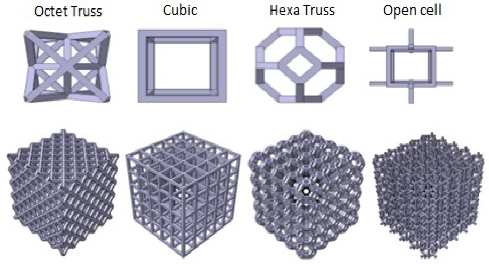
Lattice structure is a type of architecture material that combines periodically arranged 3D unit cells and hollow spaces to generate a new structure. This material can generate lightweight structures with similar or improved mechanical properties [20,21], offering great opportunities in designing high-strength and lightweight structures, such as in the automotive and aerospace industries [22]. Lattice structures are available in various types and forms as shown in Figure 1. The fundamental difference in the construction of lattice structures lies in the arrangement and stacking of unit cells in x, y and z directions. Each configuration has its own characteristics and suitability for certain applications [23].
Lattice structures are used for parts in biomedical, aerospace and automotive industries due to their unique surface structure and mechanical properties [24]. Designing parts with maximum stiffness to weight/size ratio is the primary focus in the aerospace and automobile industries, given the role of this ratio in improving fuel consumption and load capacity [25].
Apart from offering the above attributes, lattice structures have improved mechanical properties with reduced weights due to their unique cellular nature and design flexibility. Recent advancements in manufacturing techniques have enabled the production of such components [26]. Maloney et al. [27] proposed a micro-lattice 3D structure for a compact and light heat exchanger. Yin et al. [28] achieved a 25% reduction in weight for a sandwich engine hood by employing a pyramidal lattice core in an interlocking structure. Kulangara et al. [29] optimized a spur gear design using a honeycomb lattice structure, which achieved a 19% volume reduction whilst maintaining the same strength as of a normal spur gear. Syam, Wahyudin P. et al. [30] investigated the vibration characteristics of strut-based lattice structures with a specific focus on the utilization of lattice-based structures for vibration isolation whilst maintaining structural integrity. They carried out analytical, numerical and experimental analyses on six lattice-based samples whilst considering their utility as mounting for a small electric motor. The weight and vibration of the motor were treated as external forces. They achieved up to 26% reduction in vibration by using lattice-based structures.
Magerramova et al. [31] carried out experimental and numerical investigations of hollow fan blades for gas turbines with various internal structure lattice configurations. They employed the additive manufacturing technique for manufacturing these samples and found that for three types of lattice structures, the ‘strength/mass’ ratio was 1.76 to 2.36 times greater than that for solid blades. Alkebsi, Ebrahim Ahmed Ali et al. [32] designed a lattice-based gas turbine blade via lattice structure topological optimization (LSTO). They used three types of lattice structures, namely, primitive, diamond and gyroid, and achieved a weight reduction of up to 40%. They were also able to reduce the stress by up to 52% and deformation by up to 19% when subjected to a 10 MPa pressure and 1350 °C temperature.
Although many studies have examined the utilization of lattice structures in aerospace, automotive and other industrial applications for reducing weight and improving mechanical properties, the vibration characteristics are still not fully explored, especially in experimental investigations. We address this gap by exploring the utility of lattice structures in gas turbine blades in improving the vibration characteristics of these blades without compromising their structural integrity, dynamic response and operational stability. Weight reduction also improves efficiency and helps achieve high operation speeds. In view of these objectives, the vibration characteristics of lattice-based blades are investigated both experimentally and numerically in this work.
2. Materials and Methods
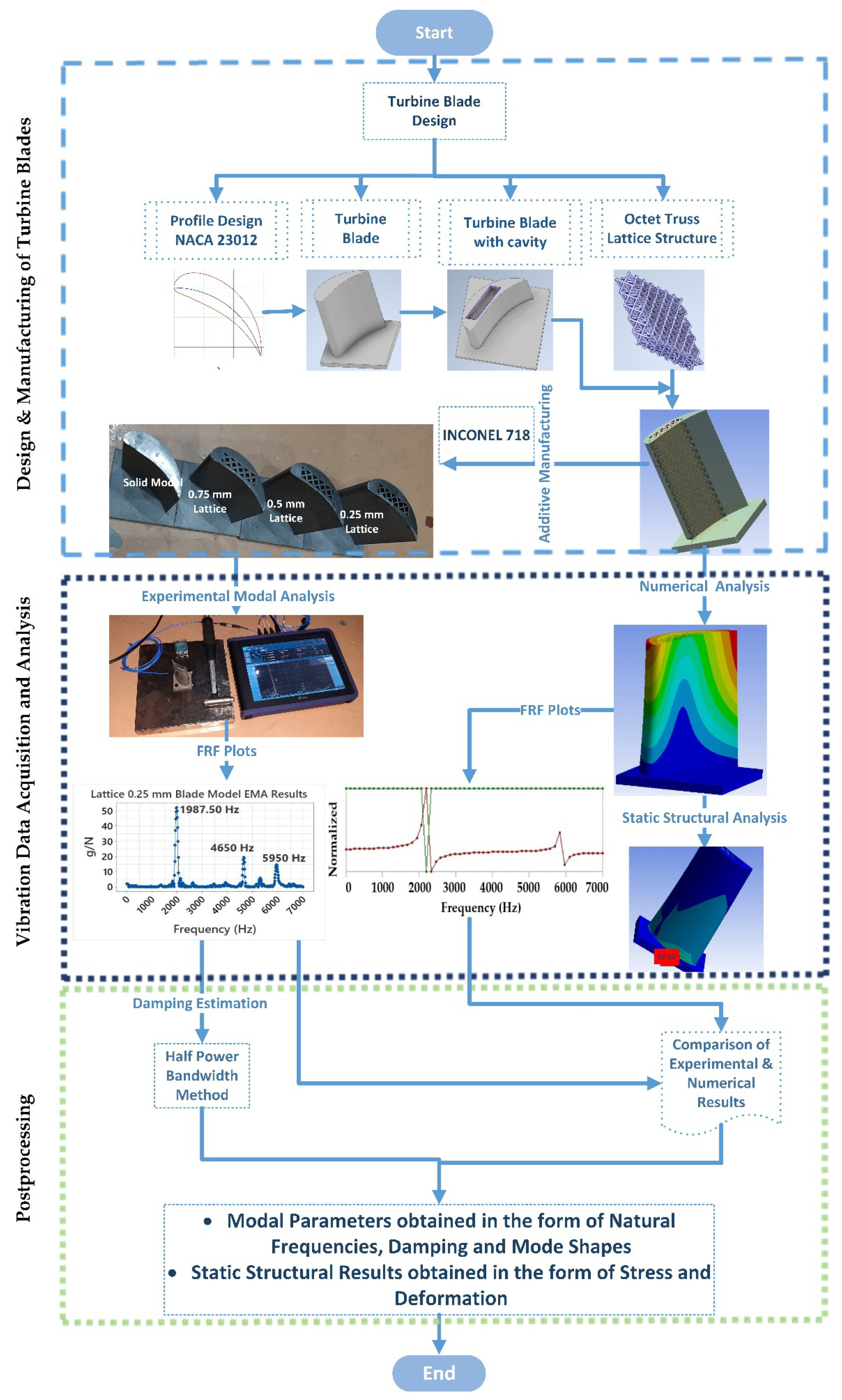
The purpose of this study is to investigate the suitability of lattice structures for use in gas turbine blades. The research framework is illustrated in Figure 2. This study involves three major steps, namely, blade design and manufacturing, vibration analysis (experimental and numerical) and post processing of experimental and numerical results.
2.1. Blade Design
A gas turbine blade based on NACA 23012 aerofoil was selected as the base design. NACA 23012 is a commonly used aerofoil type for gas turbine blades. A solid blade was designed in CAD software Autodesk Inventor (2021, Autodesk Inc., San Rafael, CA, USA) whilst taking the manufacturing constraints into account. Currently, lattice-based components can only be produced via additive manufacturing. Therefore, the blade was designed in view of the limitations of 3D printing machine, RenAM 500E (Renishaw plc, Wotton-under-Edge, England). The blade height was 60 mm, the cord length was 40 mm, and the blade radius was 30 mm. Due to their high efficiency and performance requirements, modern day gas turbines operate under rigorous environments and are subjected to high thermomechanical loads [33]. To cope with these challenging operating conditions, researchers have focused on developing various materials that suit the environment in which these turbines operate.
Nickel-based superalloys are considered the most suitable material for gas turbine blades due to their excellent ability to withstand both mechanical and thermal loads [34]. Inconel 718 is amongst the most commonly used nickel superalloys for gas turbine blades given its good mechanical properties, thermal conductivity, electrical resistivity and chemical inertia [35]. Therefore, Inconel 718 was used as the blade material in this study.
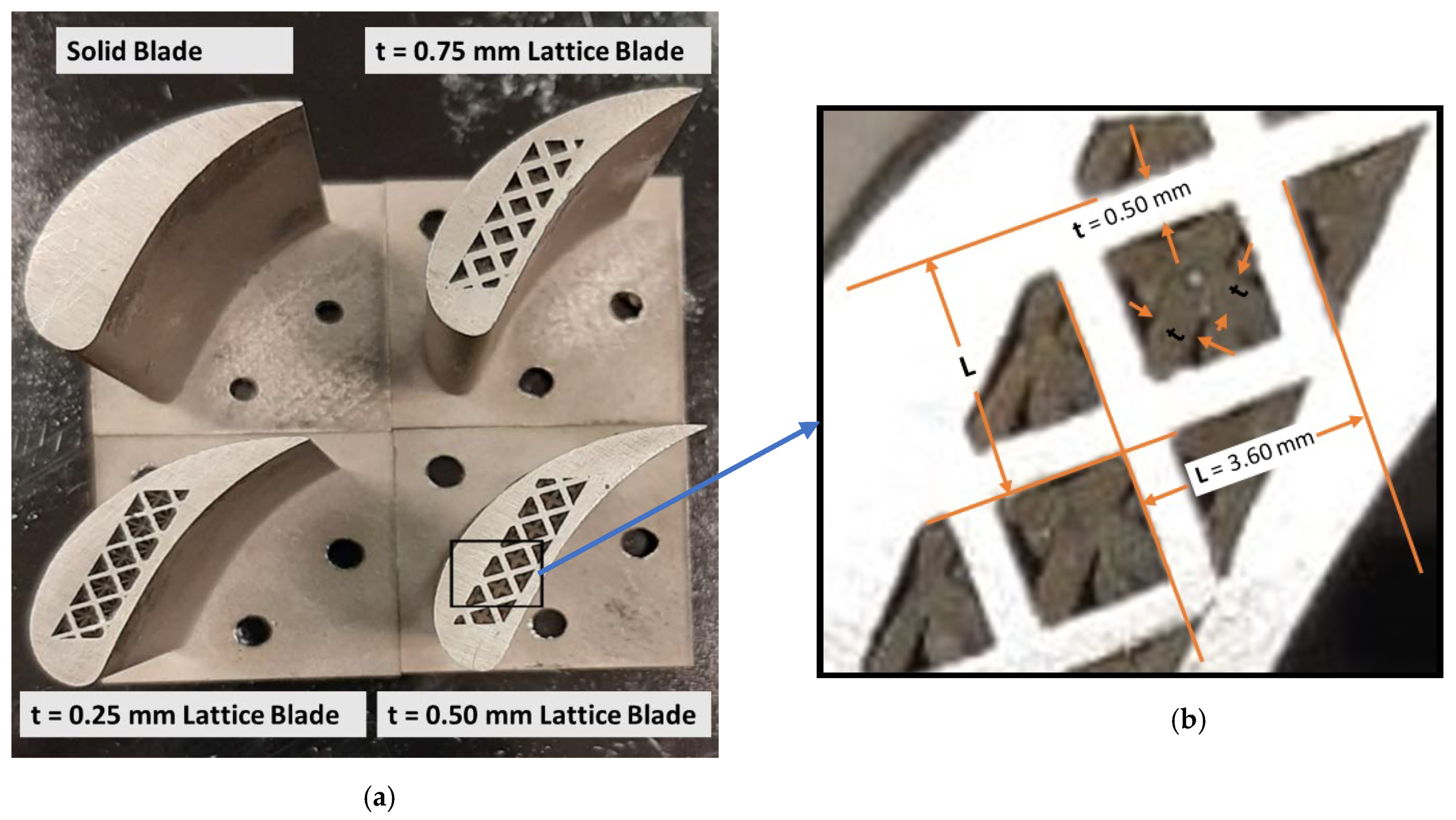
Four blade models were designed and manufactured for the experimental and numerical investigations. One of these blade models was completely solid and used as reference, whereas the three remaining blades were lattice-based. The octet truss lattice type was selected given its good dynamic properties, which can be ascribed to its shape [36]. This lattice was designed in CATIA (V5R21, Dassault Systèmes, Vélizy-Villacoublay, France). However, this software has some limitations for the minimum strut thickness of a unit cell for an octet truss lattice. The unit cell size was fixed at 3.60 × 3.60 mm for all lattice blade models, whereas the thickness (t) of struts was variable. Given that the lattice structure is porous in nature, the blade cannot be completely made of a lattice structure and should therefore be placed inside a cavity created in the solid blade. Three lattice blade models were designed by filling the cavity with different strut thicknesses of 0.75, 0.50 and 0.25 mm for the octet truss lattice as shown in Figure 3.
Given that the unit cell thickness controls the density and overall weight of the lattice model, changing the unit cell thicknesses can achieve different levels of weight reduction as shown in Table 1.
After the design, the blade models were manufactured via additive manufacturing. The selective laser meting (SLM) technique was used on a RenAM 500E machine (Renishaw plc, Wotton-under-Edge, England). Laser power of 200 W, laser speed of 875 mm/s, layer thickness of 60 μm and hatching distance of 90 μm were used as processing parameters. The resulting energy density was 42.32 J/mm3. The samples were air-cooled. Given that weight reduction was achieved using a lattice structure, we investigated the vibration characteristics of each lattice blade and compared them with those of a solid blade to determine the suitability of the lattice structure in turbine blades. Experimental modal, numerical modal and static structural analyses of each blade were carried out for this purpose.
2.2. Vibration Analysis of Turbine Blades
Vibration characteristics are amongst the key elements in turbine blade design and operation. During their operational life, turbine blades are subjected to vibratory stresses that may lead to HCF failure. Modal and static structural analyses were performed to investigate these vibration characteristics.
2.2.1. Experimental Modal Analysis of Turbine Blades
Each structure has an inherent internal frequency at which an object can naturally vibrate. At this frequency, the structure allows a transfer of energy from one form to another with minimal loss (vibrational to kinetic in this paper), thereby causing resonance. High vibration amplitudes are undesirable for any rotating machinery because they affect the operational stability, performance and life of machines and, in some cases, lead to catastrophic failure. Therefore, the frequencies at which the structure can respond erratically and result in high vibration amplitudes must be determined.
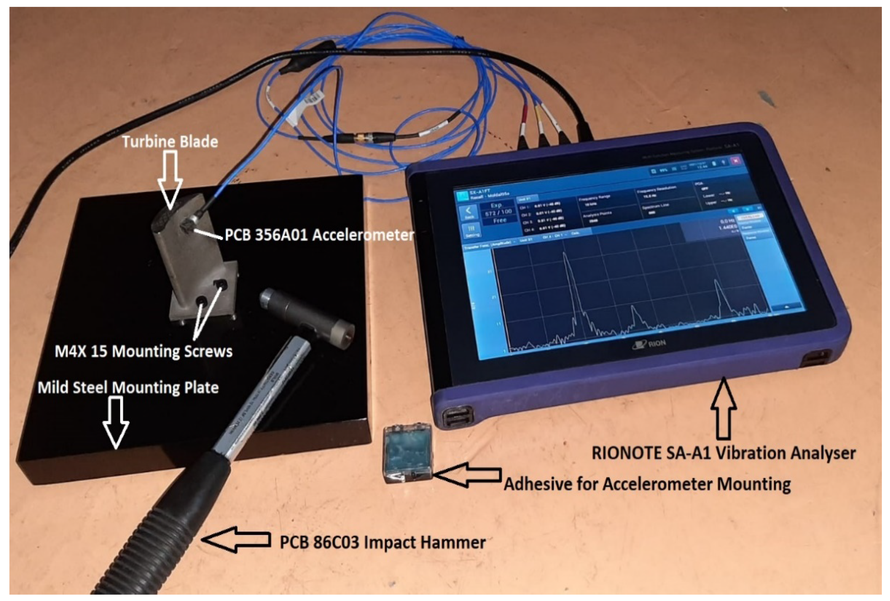
Experimental modal analysis (EMA) is an effective approach for determining natural frequencies, mode shapes and damping ratios. An experimental modal analysis was carried out in this work based on the ISO 7626-5 standard. The experimental setup included an impact hammer for applying input force, an accelerometer for measuring response and a vibration analyzer for data acquisition and analysis as shown in Figure 4.
A turbine blade was mounted on a mild steel rigid plate, and an accelerometer was mounted on the concave side of the blade using adhesive. The PCB 356A01 triaxle piezoelectric accelerometer (PCB Piezotronics, Depew, NY, USA) was used due to its miniature size and excellent accuracy. Blade mounting and sensor mounting should be rigid because any looseness will affect the accuracy of the results. The blade was then excited by using the PCB 086C03 (PCB Piezotronics, Depew, NY, USA) modally tuned impact hammer, and the response was measured in the frequency domain by using the RIONOTE SA-A1 vibration analyzer (RION Co., Ltd., Higashimotomachi Kokubunji, Japan). The transfer function of the measured signal was plotted as the ratio of the response (in terms of vibration, g) and input (in terms of applied force, N) to obtain the natural frequencies. A frequency range of 0 KHz to 7 KHz was selected. The sampling rate was 25.6 kilo samples per second. The number of FFT lines was set to 800. The force-type FFT window was selected due to its high suitability for impact testing.
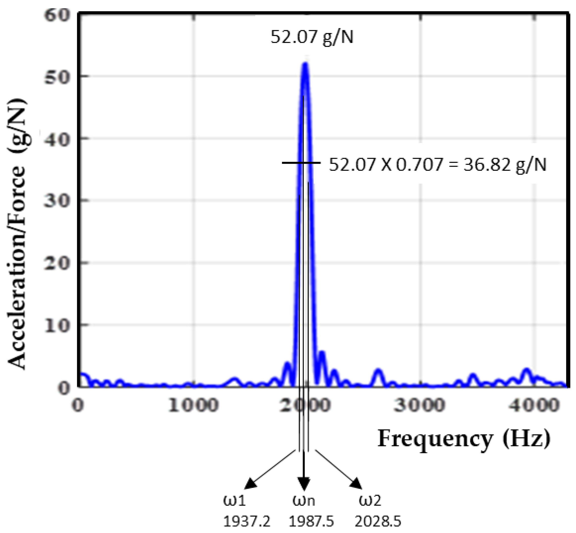
The measured signal was further processed to obtain the damping ratio corresponding to each natural frequency. Damping is an important parameter for turbine blades given its suppressing effect on vibratory stresses. The half power bandwidth method was used to calculate the damping ratio ζ for each natural frequency by using its corresponding peak as given in Equation (1):
where ζ is the damping ratio, ωn is the natural frequency and ω2 and ω1 are the maximum and minimum frequencies corresponding to the 0.707 maximum amplitude of natural frequency.
2.2.2. Numerical Modal and Harmonic Analysis of Turbine Blades
The numerical modal and harmonic analysis (NMHA) of turbine blade models was performed in ANSYS (2020 R1, ANSYS, Canonsburg, PA, USA). Modal analysis was performed by using an undamped free vibration system with the following governing Equation (2):
For the eigenvalue problem, the modal analysis was performed using the Equation (3)
Natural frequency was calculated from angular frequency ωi as
where [M] and [K] are the mass and stiffness matrix, respectively, u is the displacement vector and {ϕ}ᵢ is the mode shape corresponding to frequency fi.
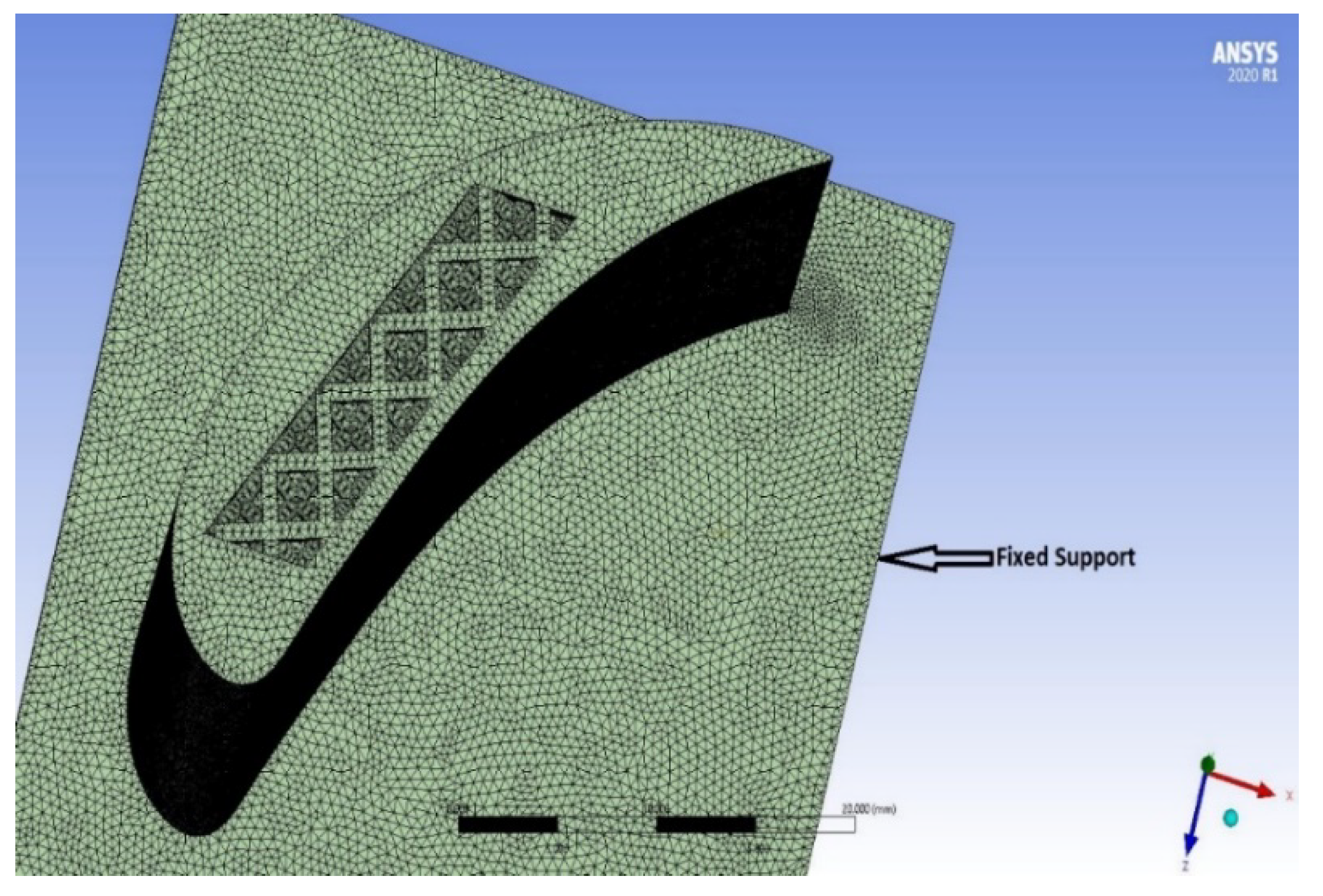
Various mode extraction methods are available in ANSYS (2020 R1, ANSYS, Canonsburg, PA, USA), including Block Lanczos, Supernode, PCG Lanczos, Unsymmetric, Damped, and QR Damped. The Block Lanczos method was selected in this work due to its high convergence rate. A tetrahedron mesh type was used. The finite element model generated 1646478 nodes and 932177 elements. Fixed support was applied at the bottom of the blade as a boundary condition. Figure 5 shows the blade model with the mesh. The material properties used in this work are listed in Table 2.
For the harmonic analysis, excitation in terms of force was applied to the blade as measured in the experimental analysis. The response was measured in the frequency domain. The peaks of the response represent the natural frequencies. Harmonic analysis can be performed in ANSYS (2020 R1, ANSYS, Canonsburg, PA, USA) by using either the mode superposition method or full method. This work employed the mode superposition method, which uses the modal analysis results before examining the harmonic response. This method is much faster than the full method, which does not use the modal history. The frequency range was set to 7000 Hz. Result clustering was also performed to obtain highly accurate results near the peaks (natural frequencies). The following governing equation was used in the mode superposition method:
where Ω is the mode shape, [C] is the damping matrix, x is the displacement and F is the force.
2.2.3. Static Structural Analysis
During their operational life, turbine blades are subjected to centrifugal forces due to shaft rotation, which induces blade root stresses. To ensure the stable and smooth operation of a turbine, these stresses must be controlled within permissible limits according to the material properties, thereby necessitating a forced response analysis to understand the severity and location of the stress and its impact on the structural integrity of the blades. In this work, the forced response of the blade was investigated via static structural analysis, which is governed by the following equation:
where [K] is constant, a linear elastic material behavior is assumed, small deflection theory is applied, no time-varying forces are considered, and no inertial effects (mass and damping) are included. A total of 3 rotational velocities (10,000, 15,000 and 20,000 rpm) were applied to the blade models, and the response was measured in terms of stress and deformation.
3. Results and Discussion
3.1. Experimental Modal Analysis Results
Experimental modal analysis results were obtained in the form of the natural frequencies of the blades and the corresponding damping ratio of each natural frequency/mode.
3.1.1. Natural Frequencies
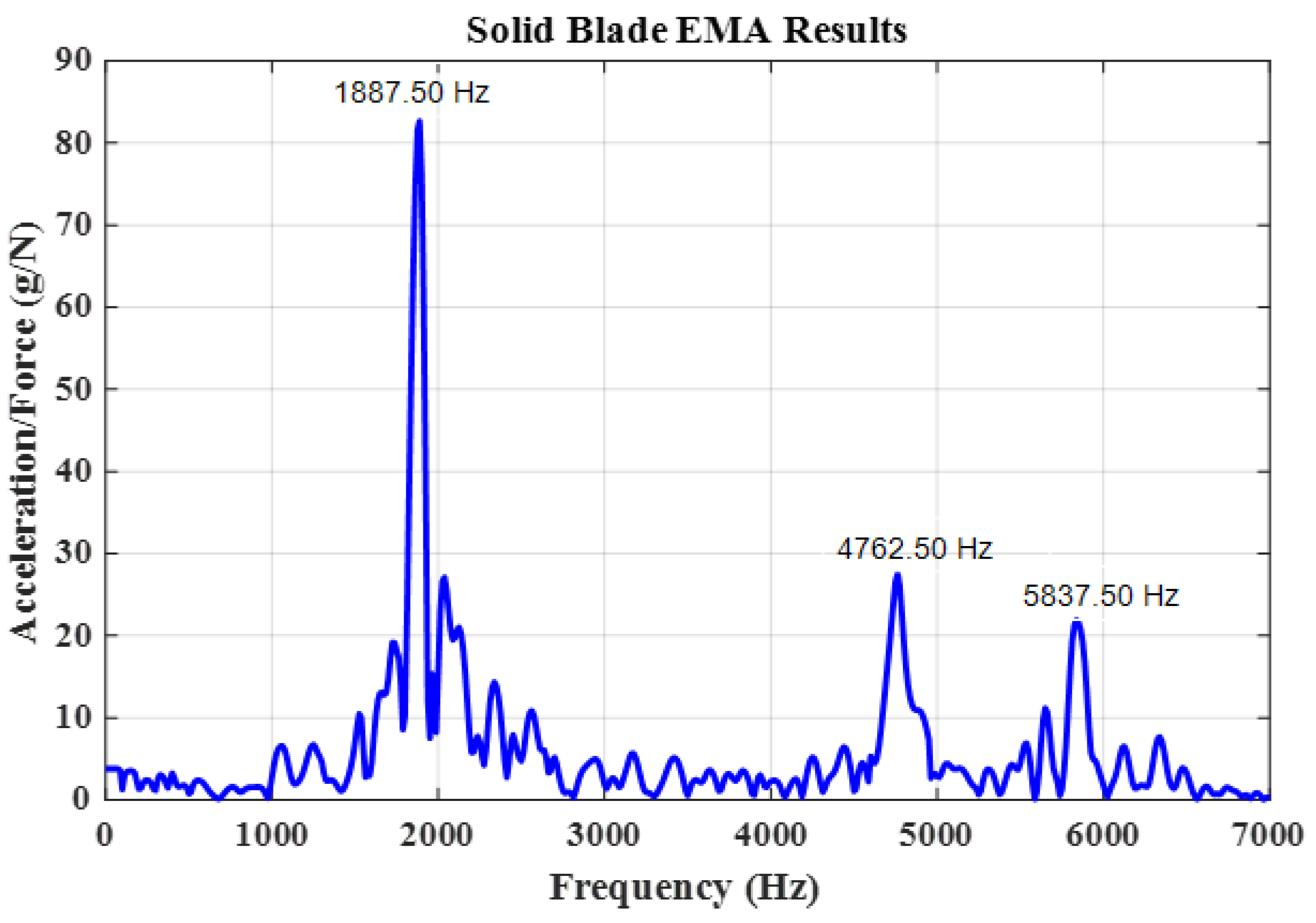
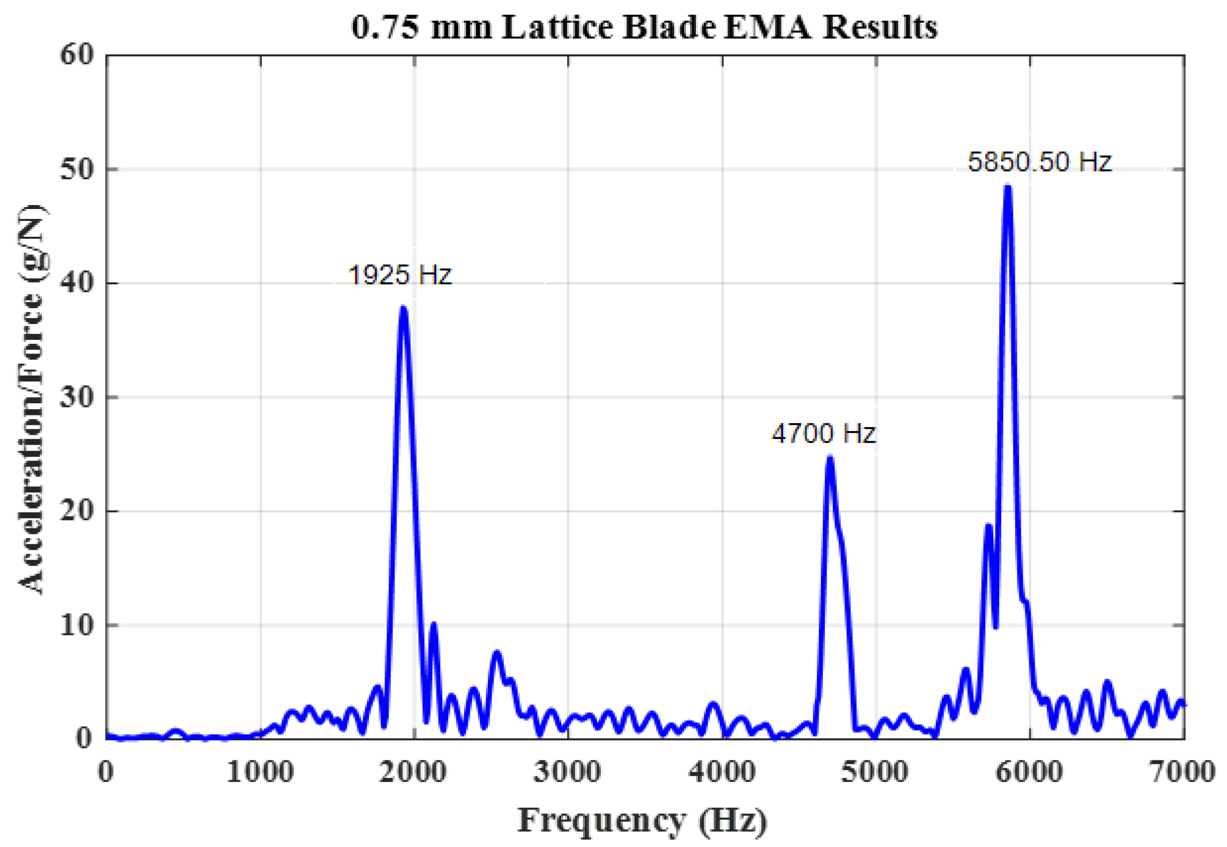
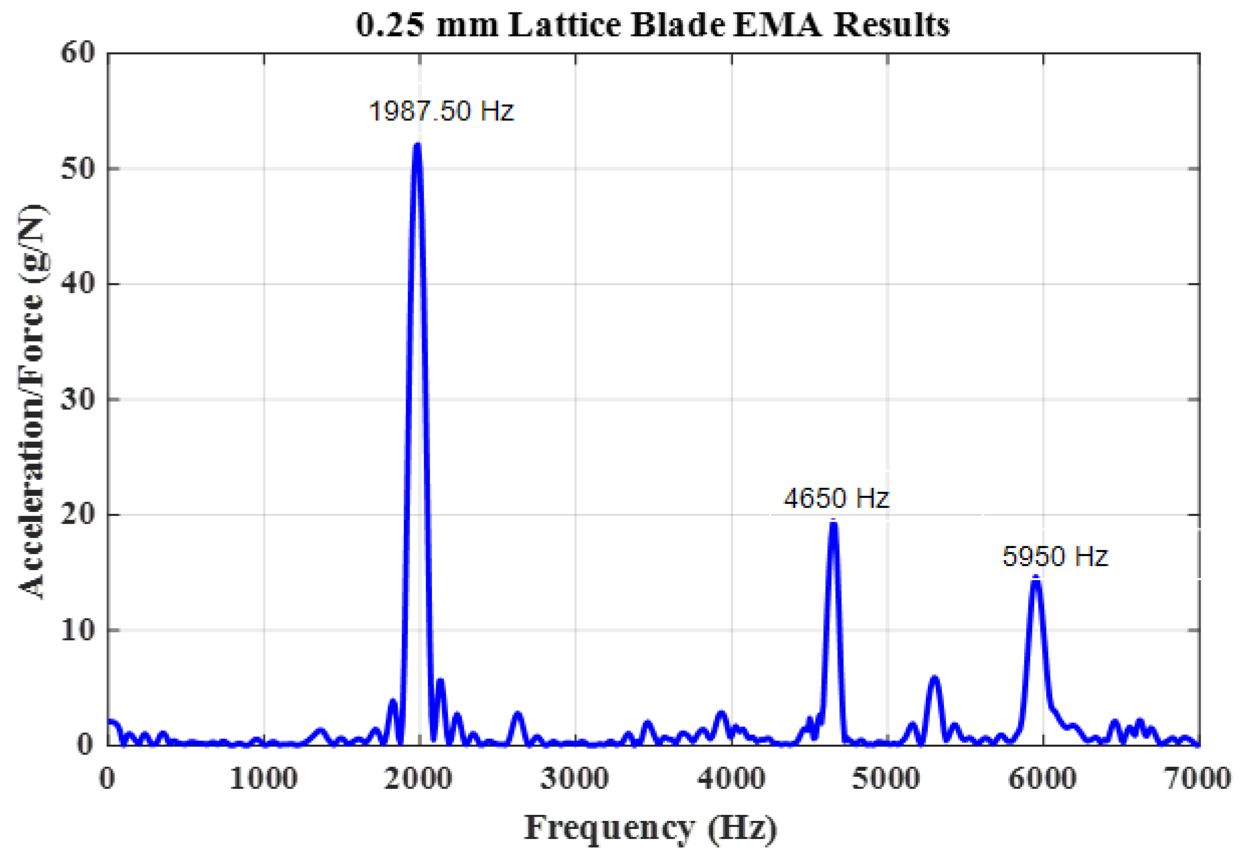
A frequency response function (FRF) plot for each type of blade model was obtained by plotting the frequency against the ratio of response (acceleration) to input force (g/N). The FRF plots of solid blade, 0.75 mm lattice blade, 0.50 mm blade and 0.25 mm blade are presented in Figure 6, Figure 7, Figure 8 and Figure 9, respectively.
The solid blade EMA frequency response plot in Figure 6 shows three clear peaks at 1887.50, 4762.50 and 5837.50 Hz, which correspond to the first, second and third natural frequencies of the solid blade, respectively. Meanwhile, the FRF plot of the 0.75 mm lattice blade model in Figure 7 shows 3 prominent peaks at 1925, 4700 and 5850.50 Hz which correspond to the first, second and third natural frequencies of the blade, respectively. Some other minor peaks were observed as well, but they cannot be associated to any natural frequency because they were undetected in the numerical analysis performed in ANSYS (2020 R1, ANSYS, Canonsburg, PA, USA).
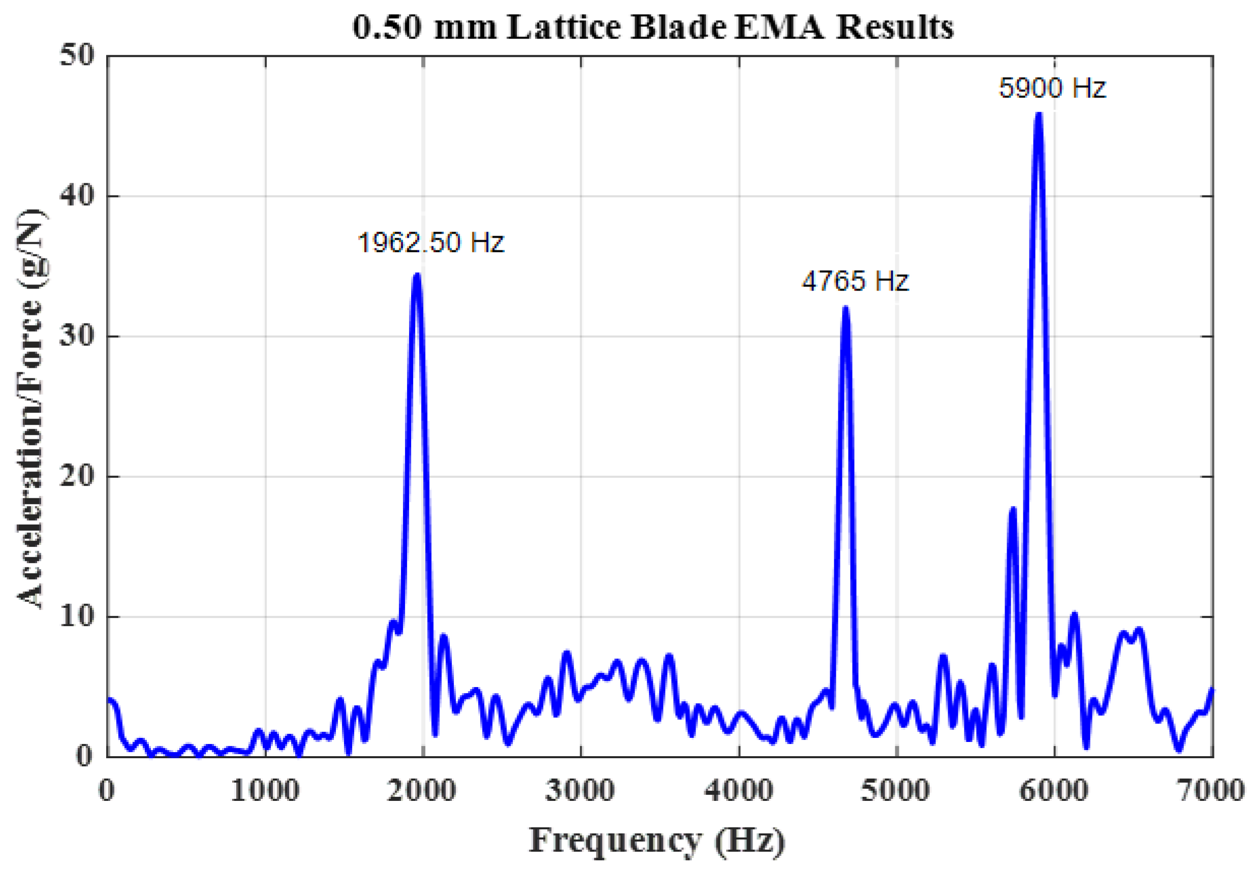
The FRF plot of the 0.50 mm lattice blade model in Figure 8 shows first, second and third natural frequencies of the blade at 1962.5, 4675 and 5900 Hz, respectively. Meanwhile, the FRF plot of the 0.25 mm lattice blade model in Figure 9 shows natural frequencies at 1987.50, 4650 and 5950 Hz.
Table 3 summarizes the natural frequencies obtained from the EMA.
Results show that lattice blades have higher natural frequencies compared with solid blade at the first and third modes. A maximum natural frequency of 1987.50 Hz was observed for the 0.25 mm lattice blade model, and a minimum natural frequency of 1887.50 Hz was observed for the solid blade model at the first mode. Moreover, the first and third natural frequencies increased along with the reduction in lattice unit cell thickness (i.e., the 0.25 mm blade had the highest natural frequencies at the first and third modes amongst all blades). Modal analysis results indicate that lattice-based blades have high overall natural frequencies. An increase in first natural frequency is always desirable in turbines because the operating speed of rigid rotors must be lower than the first natural frequency. Therefore, increasing the natural frequency can extend the operating speed of turbines as discussed by Alexandre Presas et al. [38]. The overall natural frequencies at the second and third modes were above the operational speed of most turbines and were therefore given not much importance.
3.1.2. Damping Estimation
From the EMA results, the damping ratio for each blade model was estimated at natural frequencies. Damping was estimated using the FRF plots of EMA following the procedures of S. Rani et al. [17]. Figure 10 shows the estimated damping ratio for the 0.25 mm lattice blade model at the first natural frequency. The damping ratios for all four blade models were computed in MATLAB (2020R1, The Mathworks, Inc., Natick, MA, USA) and the results are presented in Table 4.
The above damping results indicate that the maximum damping ratio is observed at the first mode for all blade models. Lattice blade models have a slightly higher damping ratio at the first mode compared with solid blades. Maximum damping was observed at the first mode for all blade models with a maximum value of 0.0251 for the 0.75 mm lattice blade model. No significant differences were observed in the damping ratios of the blade models at their respective modes. High damping ratios are always desired to dissipate vibration energy and to consequently reduce the vibratory stresses, hence ultimately extending the lifetime of turbine blades by reducing the severity of HCF [39].
3.2. Numerical Modal and Harmonic Analysis Results for Turbine Blades
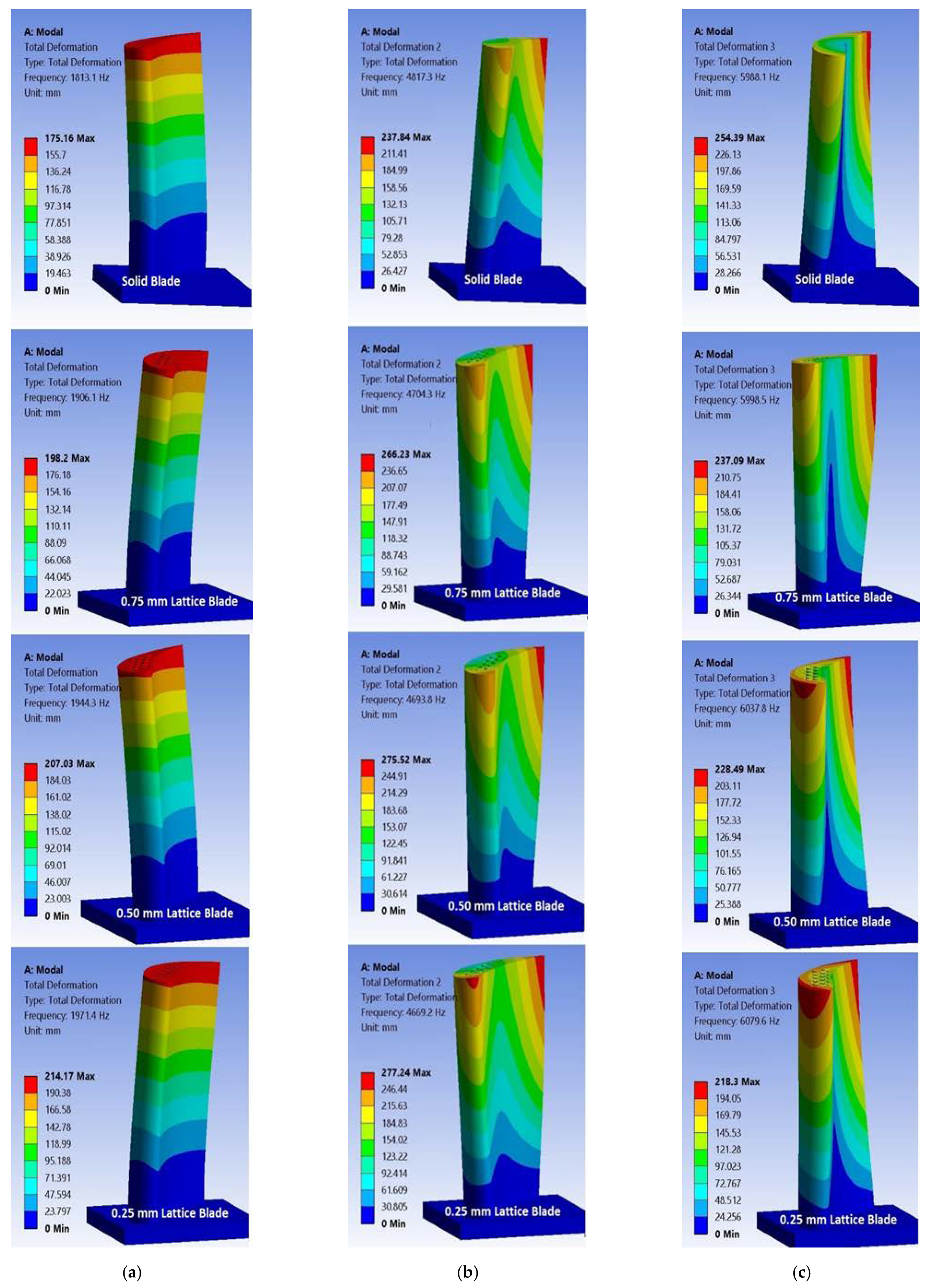
The first three modes of the turbine blades were investigated in the numerical modal analysis using ANSYS. The results were presented in the form of natural frequencies and mode shapes as shown in Figure 11 and Table 5.
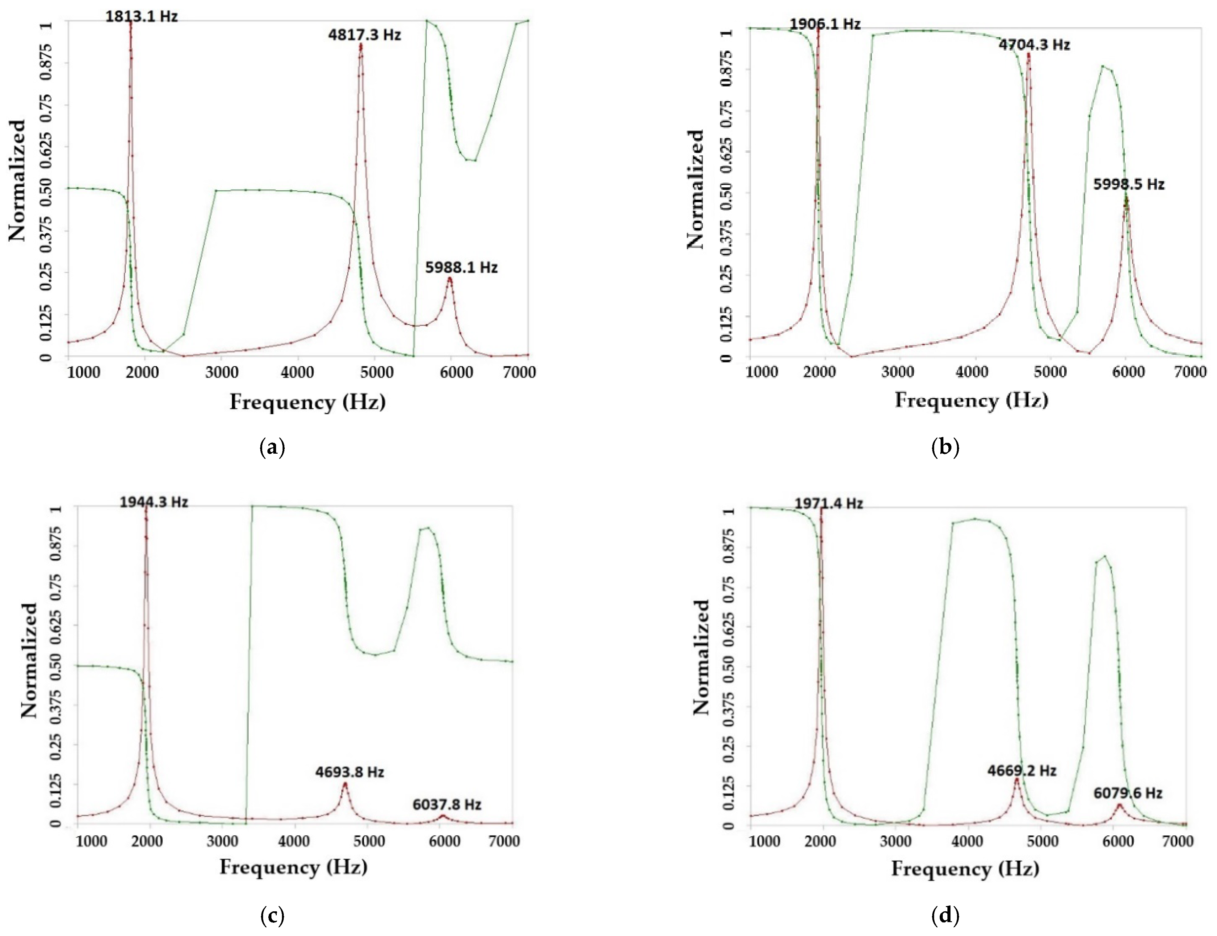
Results indicate that for all four blade models, the first mode is the flap wise bending mode as shown in Figure 11a. At this mode, a natural frequency of 1971.40 Hz was observed for the 0.25 mm lattice blade model, whereas the lowest natural frequency of 1813.10 Hz was observed for the solid blade model. The first natural frequency for the lattice-based blade was approximately 8% higher than that for the solid blade. For the second mode, which is torsional mode as shown in Figure 11b, the trend was reversed where the highest natural frequency was observed for the solid blade. Torsion was also observed at the third mode as shown in Figure 11c, but here the highest natural frequency was observed for the 0.25 mm lattice-based blade (3% higher than that of the solid blade). The harmonic analysis results were presented in the form of both amplitude and phase. Given that each peak is associated with natural frequency, the phase also changes at natural frequencies, thereby validating the natural frequencies/modes. The harmonic response for each blade model is presented in Figure 12.
3.3. Static Structural Analysis Results
3.3.1. Stress Analysis
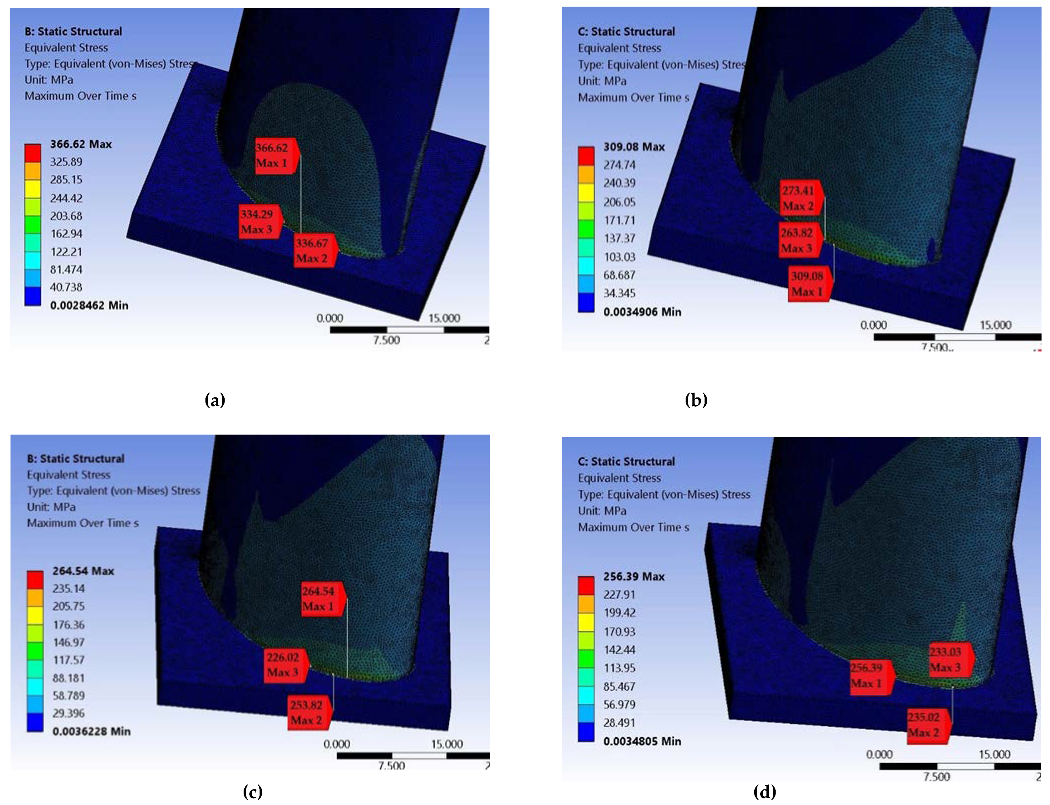
Static structural analysis results indicate that amongst all four blade models, the maximum stress was observed for the solid blade model at all rotational speeds, whereas the lowest stress was observed for the 0.25 mm lattice blade model. Figure 13 shows the stress level.
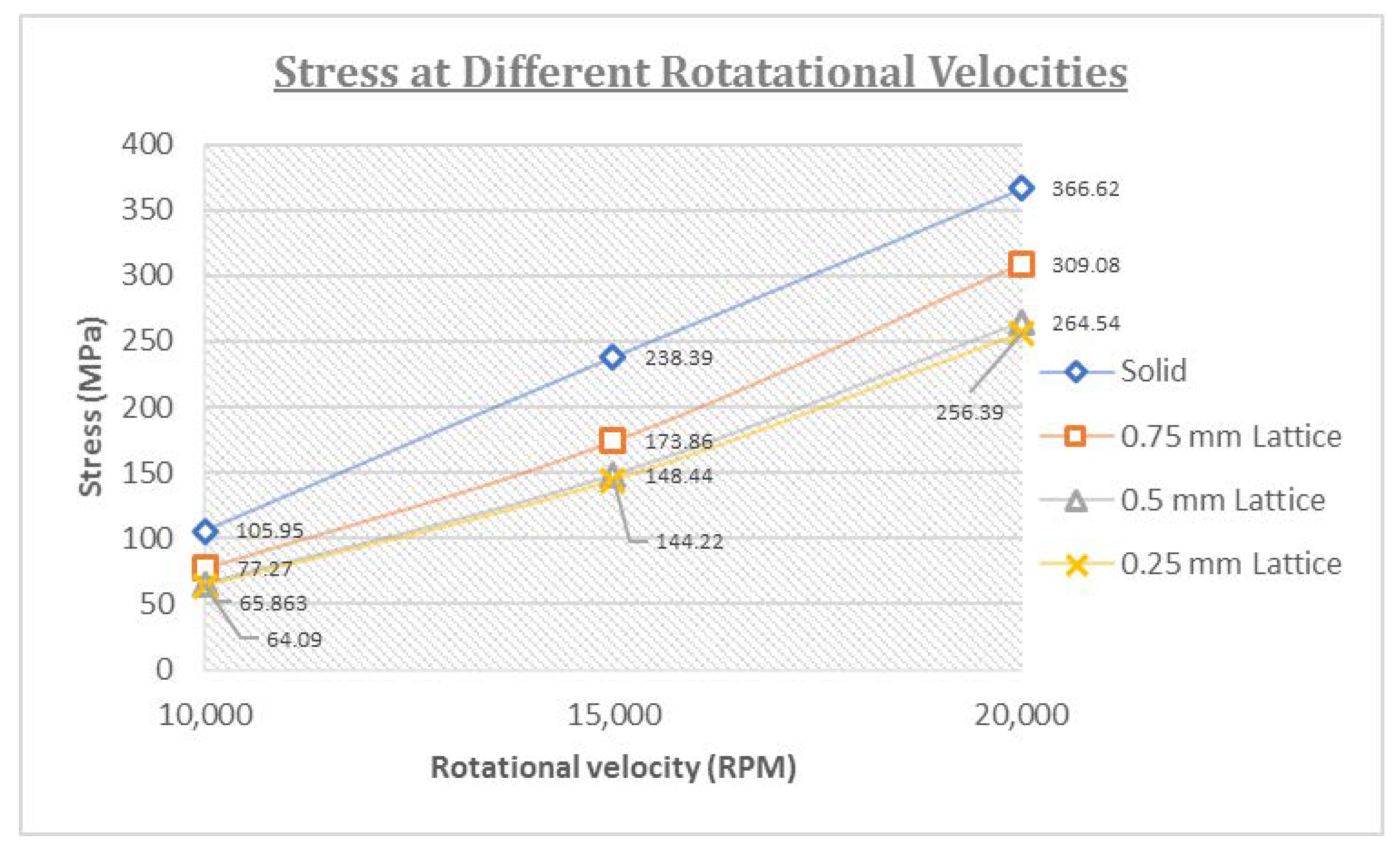
The maximum stress was detected at the root of the blades where they were mounted to the turbine wheel. The amount of stress induced due to rotation increased along with the rotational speed of the turbine. Figure 14 summarizes these results.
For the lattice blade models, decreasing the thickness of struts also reduced the stress level. Amongst the lattice models, the 0.25 mm lattice model had the lowest stress, followed by the 0.50 mm and 0.75 mm lattice blade models. Meanwhile, the solid model demonstrated the highest stress level amongst all four blades as shown in Figure 14. Both the weight and stress reductions resulting from reduced strut thickness are desirable in high-speed rotational machineries, such as turbines. These blades achieved maximum stress reductions of 38.60%, 39.50% and 30.06% at 10,000, 15,000 and 20,000 rpm, respectively, compared with solid blades. Alkebsi et al. [32] observed a reduction in stress and deformation levels for a gas turbine blade whose lattice configuration differs from that of a solid blade.
3.3.2. Total Deformation
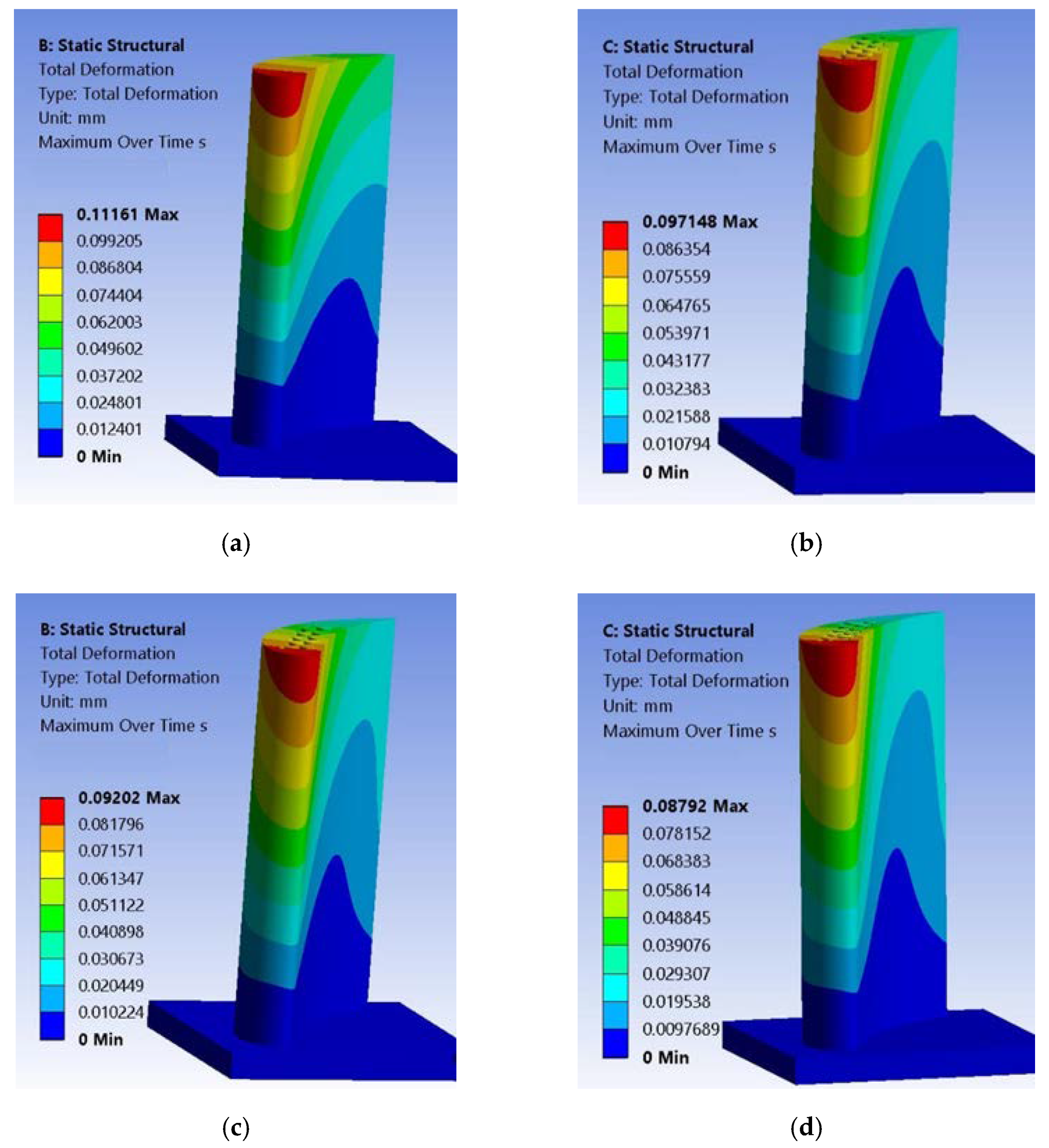
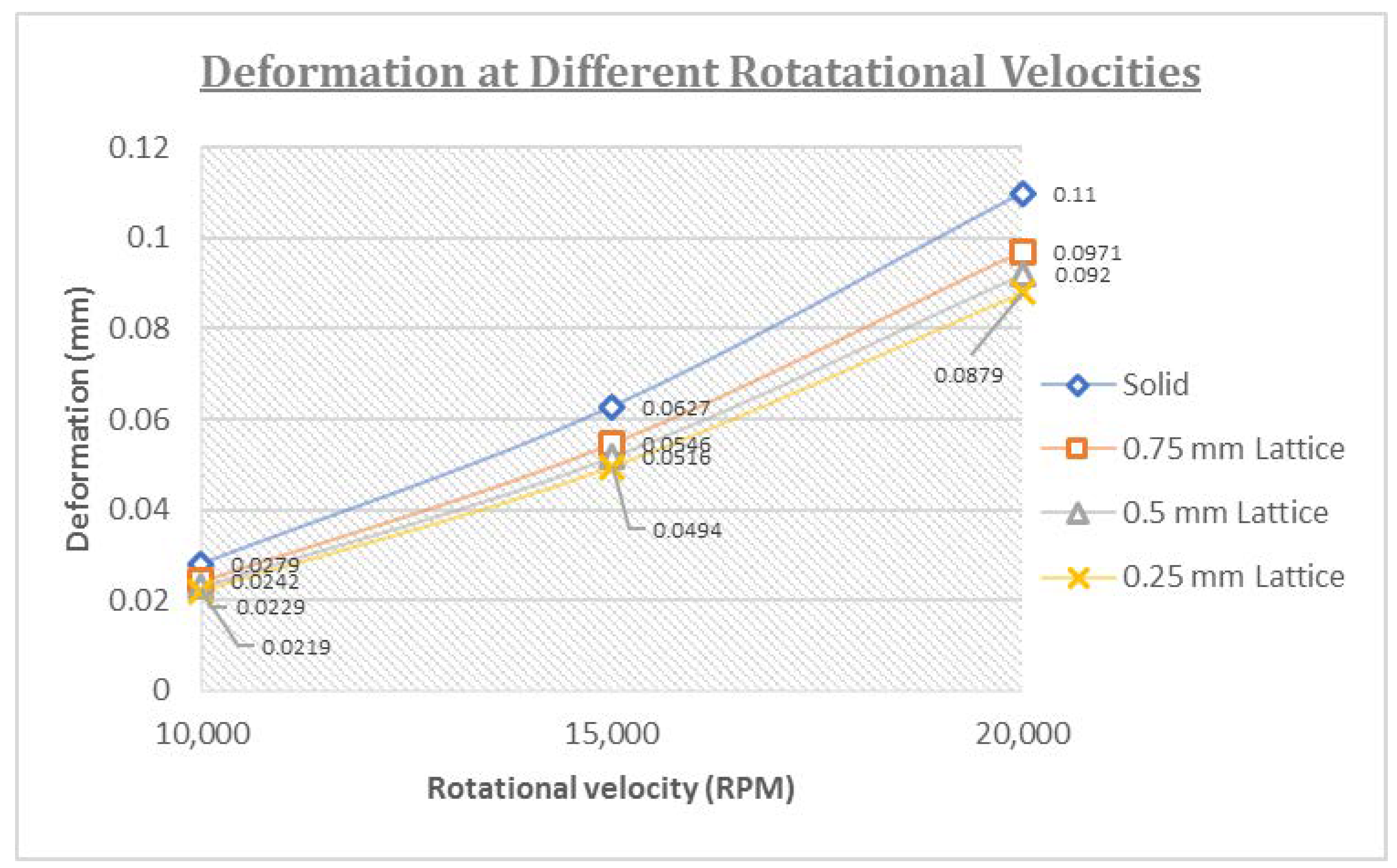
Figure 15 presents the deformation results obtained from the static structural analysis at 10,000, 15,000 and 20,000 rpm. The maximum total deformation was observed at the top of the blades. Following the stress trend, total deformation also increased along with rotation speed. At each rotational velocity, the 0.25 mm lattice blade model and the solid blade model had the lowest and highest total deformations, respectively. The maximum reductions in deformation for the lattice blades were observed as 21.5%, 21.20% and 20.09% at 10,000, 15,000 and 20,000 rpm, respectively, compared with solid blades. Figure 16 summarizes the results.
3.4. Comparison of Experimental and Numerical Natural Frequencies
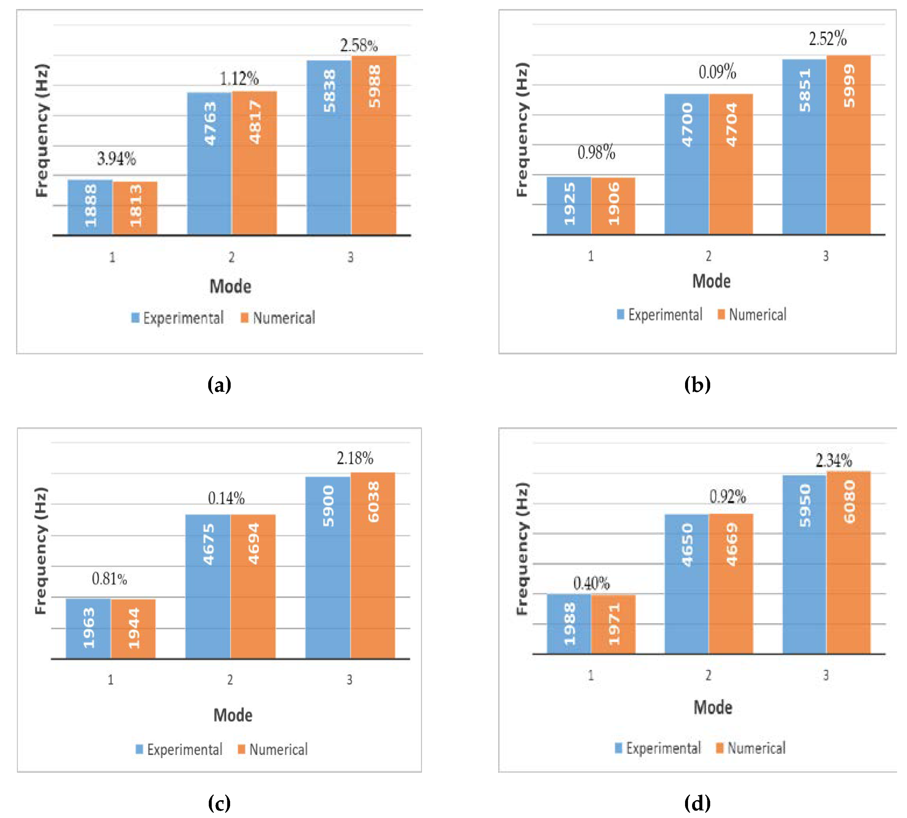
Experimental and numerical modal analyses were performed for the four blade models. Frequency response function plots as a ratio of response (vibration, g) and input (applied force, N) were obtained experimentally and numerically. Experimental and numerical results were then compared in terms of percentage error by taking the experimental results as reference. Figure 17 presents the results.
For the 0.75, 0.50 and 0.25 mm lattice blades, the maximum error was observed at the third mode with values of 2.52%, 2.34% and 2.18%, respectively. The minimum error for all blade models was observed at the second mode. The slight difference in the results may be attributed to some data acquisition and analysis limitations and to the minor differences in the mechanical properties of the experimental and numerical models.
4. Conclusions
This work investigates the utilization of the octet truss lattice structure in turbine blades by using experimental and numerical vibration analysis techniques. Based on the results, the following conclusions are drawn.
- Using octet truss lattice structure with unit cell strut thicknesses of 0.75, 0.50 and 0.25 mm, weight reduction of 15.58%, 20.78% and 24.91% was achieved, respectively;
- Both EMA and NMHA results indicated that the first and third natural frequencies increased in the lattice base blades. Moreover, natural frequencies increase with the decrease in strut thickness of unit cell for first and third modes;
- A maximum difference of 3.94% was observed between the EMA and NMHA results, hence suggesting that these results were generally in good agreement;
- Stress reduction up to 39.50% and reduction in deformation up to 21.50% was observed in lattice-based turbine blades compared to solid blade. Both stress and deformation levels decrease by decreasing strut thickness of unit cells.
Hence, we can conclude that octet truss lattice structures can be utilized in turbine blades to significantly reduce weight, stress level and deformation along with an increasing first natural frequency. All these attributes are highly desirable for ensuring the efficiency, stability and durability of turbine blades throughout their operational life.
Author Contributions
Conceptualization, S.H. and W.A.W.G.; methodology, S.H. and A.H.A.; software, W.A.W.G. and S.H.; validation, S.H., S.S.K.S. and W.A.W.G.; formal analysis, S.H.; investigation, S.H.; resources, W.A.W.G.; data curation, W.A.W.G. and S.S.K.S.; writing—original draft preparation, S.H.; writing—review and editing, S.A., S.S.K.S. and W.A.W.G.; visualization, A.H.A.; supervision, W.A.W.G.; project administration, W.A.W.G.; funding acquisition, W.A.W.G. All authors have read and agreed to the published version of the manuscript.
Funding
The authors wish to show their gratitude to the Universiti Kebangsaan Malaysia (UKM) for its research funding GUP-2018-078.
Institutional Review Board Statement
Not applicable.
Informed Consent Statement
Not applicable.
Data Availability Statement
Data are available upon request from the corresponding author. These data are not commercially available due to privacy issues.
Acknowledgments
The authors would like to acknowledge Jabbar Bin Jamaluddin, Hafizan Kamaruddin and Che Wan Amirulfikri for their support in design and fabrication process.
Conflicts of Interest
The authors declared no conflict of interest and had no commercial or associative interests that represent a conflict of interest in connection with the work submitted.
References
- Murugan, M.; Ghoshal, A.; Xu, F.; Hsu, M.C.; Bazilevs, Y.; Bravo, L.; Kerner, K. Analytical Study of Articulating Turbine Rotor Blade Concept for Improved Off-Design Performance of Gas Turbine Engines. J. Eng. Gas Turbines Power 2017, 139, 102601. [Google Scholar] [CrossRef] [Green Version]
- Hosseinimaab, S.M.; Tousi, A.M. A New Approach to Off-Design Performance Analysis of Gas Turbine Engines and Its Application. Energy Convers. Manag. 2021, 243, 114411. [Google Scholar] [CrossRef]
- Bornassi, S.; Ghalandari, M.; Maghrebi, S.F. Blade Synchronous Vibration Measurements of a New Upgraded Heavy Duty Gas Turbine MGT-70(3) by Using Tip-Timing Method. Mech. Res. Commun. 2020, 104, 103484. [Google Scholar] [CrossRef]
- Naik, P.; Lehmayr, B.; Homeier, S.; Klaus, M.; Vogt, D.M. Influence of Turbocharger Turbine Blade Geometry on Vibratory Blade Stresses. J. Eng. Gas Turbines Power 2019, 141, 021015. [Google Scholar] [CrossRef]
- Adamsab, K. CFD Investigation of Unsteady Aerodynamics in Gas Turbine Engine Blade Surface. Mater. Today Proc. 2020, 44, 4661–4665. [Google Scholar] [CrossRef]
- Priya, T.D.; Kumar, S.; Pratap, D.; Shylaja, S.; Satish, T.N.; Rao, A.N.V. Rotor Blade Vibration Measurement on Aero Gas Turbine Engines. In Proceedings of the National Aerospace Propulsion Conference, Lecture Notes in Mechanical Engineering; Mistry, C., Kumar, S., Raghunandan, B., Sivaramakrishna, G., Eds.; Springer: Singapore, 2020; pp. 263–273. [Google Scholar] [CrossRef]
- Zhang, B.; Ding, H.; Chen, L.Q. Super-Harmonic Resonances of a Rotating Pre-Deformed Blade Subjected to Gas Pressure. Nonlinear Dyn. 2019, 98, 2531–2549. [Google Scholar] [CrossRef]
- Spodniak, M.; Semrad, K.; Hovanec, M.; Al-Rabeei, S.A.S.; Hesko, F. Deformation States of the Selected Mechanical Component during the Harmonic Analysis. In Proceedings of the NTinAD 2020—New Trends in Aviation Development 2020, Stary Smokovec, Slovakia, 17–18 September 2020; pp. 211–214. [Google Scholar] [CrossRef]
- Saito, A.; Kuno, T. Data-Driven Experimental Modal Analysis by Dynamic Mode Decomposition. J. Sound Vib. 2020, 481, 115434. [Google Scholar] [CrossRef]
- Meng, X.; Zhao, Y.; Lu, J.; Huang, S.; Zhou, J.; Su, C. Improvement of Damping Property and Its Effects on the Vibration Fatigue in Ti6Al4V Titanium Alloy Treated by Warm Laser Shock Peening. Metals 2019, 9, 746. [Google Scholar] [CrossRef] [Green Version]
- Zippo, A.; Iarriccio, G.; Pellicano, F.; Shmatko, T. Vibrations of Plates with Complex Shape: Experimental Modal Analysis, Finite Element Method, and R-Functions Method. Shock. Vib. 2020, 8882867. [Google Scholar] [CrossRef]
- Li, J.; Yang, S.; Yang, J.; Li, F.; Zeng, Q.; Shao, J.; Chang, C.; Wu, N.; Chen, Y.; Li, K. Low-Order Radial Modal Test and Analysis of Drive Motor Stator. Machines 2021, 9, 97. [Google Scholar] [CrossRef]
- Yang, W.; Liang, M.; Wang, L.; Yuan, H. Research on Unbalance Response Characteristics of Gas Turbine Blade-Disk Rotor System. J. Vibroengineering 2018, 20, 1676–1690. [Google Scholar] [CrossRef]
- Zhao, W.; Li, Y.; Xue, M.; Wang, P.; Jiang, J. Vibration Analysis for Failure Detection in Low Pressure Steam Turbine Blades in Nuclear Power Plant. Eng. Fail. Anal. 2018, 84, 11–24. [Google Scholar] [CrossRef]
- Kong, Y.S.; Abdullah, S.; Schramm, D.; Omar, M.Z.; Haris, S.M. Vibration Fatigue Analysis of Carbon Steel Coil Spring under Various Road Excitations. Metals 2018, 8, 617. [Google Scholar] [CrossRef] [Green Version]
- Abdelkader, M.; Noman, M.T.; Amor, N.; Petru, M.; Mahmood, A. Combined Use of Modal Analysis and Machine Learning for Materials Classification. Materials 2021, 14, 4270. [Google Scholar] [CrossRef] [PubMed]
- Rani, S.; Agrawal, A.K.; Rastogi, V. Vibration Analysis for Detecting Failure Mode and Crack Location in First Stage Gas Turbine Blade. J. Mech. Sci. Technol. 2019, 33, 2671–2680. [Google Scholar] [CrossRef]
- Hanouf, Z.; Faris, W.F.; Nor, M.J.M. Dynamic Characterization of Car Door and Hood Panels Using FEA and EMA. Proc. Appl. Mech. Mater. 2014, 471, 89–96. Available online: https://www.scientific.net/AMM.471.89 (accessed on 12 December 2021).
- Costa, P.; Nwawe, R.; Soares, H.; Reis, L.; Freitas, M.; Chen, Y.; Montalvão, D. Review of Multiaxial Testing for Very High Cycle Fatigue: From “Conventional” to Ultrasonic Machines. Machines 2020, 8, 25. [Google Scholar] [CrossRef]
- Helou, M.; Kara, S. Design, Analysis and Manufacturing of Lattice Structures: An Overview. Int. J. Comput. Integr. Manuf. 2018, 31, 243–261. [Google Scholar] [CrossRef]
- Nguyen, D.S. Design of Lattice Structure for Additive Manufacturing in CAD Environment. J. Adv. Mech. Des. Syst. Manuf. 2019, 13, jamdsm0057. [Google Scholar] [CrossRef] [Green Version]
- Pan, C.; Han, Y.; Lu, J. Design and Optimization of Lattice Structures: A Review. Appl. Sci. 2020, 10, 6374. [Google Scholar] [CrossRef]
- Seharing, A.; Azman, A.H.; Abdullah, S. A Review on Integration of Lightweight Gradient Lattice Structures in Additive Manufacturing Parts. Adv. Mech. Eng. 2020, 12, 1687814020916951. [Google Scholar] [CrossRef]
- Maconachie, T.; Leary, M.; Lozanovski, B.; Zhang, X.; Qian, M.; Faruque, O.; Brandt, M. SLM Lattice Structures: Properties, Performance, Applications and Challenges. Mater. Des. 2019, 183, 108137. [Google Scholar] [CrossRef]
- Du, Y.; Gu, D.; Xi, L.; Dai, D.; Gao, T.; Zhu, J.; Ma, C. Laser Additive Manufacturing of Bio-Inspired Lattice Structure: Forming Quality, Microstructure and Energy Absorption Behavior. Mater. Sci. Eng. A 2020, 773, 138857. [Google Scholar] [CrossRef]
- Duan, S.; Xi, L.; Wen, W.; Fang, D. Mechanical Performance of Topology-Optimized 3D Lattice Materials Manufactured via Selective Laser Sintering. Compos. Struct. 2020, 238, 111985. [Google Scholar] [CrossRef]
- Maloney, K.J.; Fink, K.D.; Schaedler, T.A.; Kolodziejska, J.A.; Jacobsen, A.J.; Roper, C.S. Multifunctional Heat Exchangers Derived from Three-Dimensional Micro-Lattice Structures. Int. J. Heat Mass Transf. 2012, 55, 2486–2493. [Google Scholar] [CrossRef]
- Yin, S.; Chen, H.; Wu, Y.; Li, Y.; Xu, J. Introducing Composite Lattice Core Sandwich Structure as an Alternative Proposal for Engine Hood. Compos. Struct. 2018, 201, 131–140. [Google Scholar] [CrossRef]
- Kulangara, A.J.; Rao, C.S.P.; Subhash Chandra Bose, P. Generation and Optimization of Lattice Structure on a Spur Gear. Proc. Mater. Today 2018, 5, 5068–5073. [Google Scholar] [CrossRef]
- Syam, W.P.; Jianwei, W.; Zhao, B.; Maskery, I.; Elmadih, W.; Leach, R. Design and Analysis of Strut-Based Lattice Structures for Vibration Isolation. Precis. Eng. 2018, 52, 494–506. [Google Scholar] [CrossRef]
- Magerramova, L.; Volkov, M.; Afonin, A.; Svinareva, M.; Kalinin, D. Application of Light Lattice Structures for Gas Turbine Engine Fan Blades. In Proceedings of the 31st Congress of the International Council of the Aeronautical Sciences, ICAS 2018, Belo Horizonte, Brazil, 9–14 September 2018. [Google Scholar]
- Alkebsi, E.A.A.; Ameddah, H.; Outtas, T.; Almutawakel, A. Design of Graded Lattice Structures in Turbine Blades Using Topology Optimization. Int. J. Comput. Integr. Manuf. 2021, 34, 370–384. [Google Scholar] [CrossRef]
- Ludwig, C.; Rabold, F.; Kuna, M.; Schurig, M.; Schlums, H. Simulation of Anisotropic Crack Growth Behavior of Nickel Base Alloys under Thermomechanical Fatigue. Eng. Fract. Mech. 2020, 224, 106800. [Google Scholar] [CrossRef]
- Šmíd, M.; Horník, V.; Kunz, L.; Hrbáček, K.; Hutař, P. High Cycle Fatigue Data Transferability of MAR-M 247 Superalloy from Separately Cast Specimens to Real Gas Turbine Blade. Metals 2020, 10, 1460. [Google Scholar] [CrossRef]
- Witkin, D.B.; Patel, D.; Albright, T.V.; Bean, G.E.; McLouth, T. Influence of Surface Conditions and Specimen Orientation on High Cycle Fatigue Properties of Inconel 718 Prepared by Laser Powder Bed Fusion. Int. J. Fatigue 2020, 132, 105392. [Google Scholar] [CrossRef]
- Dong, L.; Deshpande, V.; Wadley, H. Mechanical Response of Ti-6Al-4V Octet-Truss Lattice Structures. Int. J. Solids Struct. 2015, 60, 107–124. [Google Scholar] [CrossRef]
- Qiu, X.; Cheng, X.; Dong, P.; Peng, H.; Xing, Y.; Zhou, X. Sensitivity Analysis of Johnson-Cook Material Constants and Friction Coeffcient Influence on Finite Element Simulation of Turning Inconel 718. Materials 2019, 12, 3121. [Google Scholar] [CrossRef] [PubMed] [Green Version]
- Presas, A.; Valentin, D.; Valero, C.; Egusquiza, M.; Egusquiza, E. Experimental Measurements of the Natural Frequencies and Mode Shapes of Rotating Disk-Blades-Disk Assemblies from the Stationary Frame. Appl. Sci. 2019, 9, 3864. [Google Scholar] [CrossRef] [Green Version]
- Chen, Y.G.; Zhu, Q.Y.; Zhai, J.Y. Experimental Investigation on Fatigue of Blade Specimen Subjected to Resonance and Effect of a Damping Hard Coating Treatment. J. Cent. South Univ. 2021, 28, 445–453. [Google Scholar] [CrossRef]
Figure 1.
Various configurations of lattice structures.

Figure 2.
Research framework.

Figure 3.
(a) Turbine blade models with variable strut thickness, t; and (b) unit cell dimensions of t = 0.50 mm lattice blade.
Figure 3.
(a) Turbine blade models with variable strut thickness, t; and (b) unit cell dimensions of t = 0.50 mm lattice blade.

Figure 4.
Experimental setup for the modal analysis.

Figure 5.
Mesh view of the 0.75 mm lattice blade.

Figure 6.
Solid blade EMA natural frequencies.

Figure 7.
The 0.75 mm lattice blade EMA natural frequencies.

Figure 8.
The 0.50 mm lattice blade EMA natural frequencies.

Figure 9.
The 0.25 mm lattice blade EMA natural frequencies.

Figure 10.
Damping estimation of the 0.25 mm lattice model at the first mode.

Figure 11.
Mode shapes of turbine blades. (a) First mode; (b) second Mode; and (c) third mode.

Figure 12.
(a) Solid blade harmonic response; (b) 0.75 mm lattice blade harmonic response; (c) 0.50 mm lattice blade harmonic response; and (d) 0.25 mm lattice blade harmonic response.
Figure 12.
(a) Solid blade harmonic response; (b) 0.75 mm lattice blade harmonic response; (c) 0.50 mm lattice blade harmonic response; and (d) 0.25 mm lattice blade harmonic response.

Figure 13.
Stress at 20,000 rpm (a) Solid blade; (b) 0.75 mm lattice blade; (c) 0.50 mm lattice blade; and (d) 0.25 mm lattice blade.
Figure 13.
Stress at 20,000 rpm (a) Solid blade; (b) 0.75 mm lattice blade; (c) 0.50 mm lattice blade; and (d) 0.25 mm lattice blade.

Figure 14.
Stress in turbine blades at different rotational speeds.

Figure 15.
Deformation at 20,000 rpm. (a) Solid blade; (b) 0.75 mm lattice blade; (c) 0.50 mm lattice blade; and (d) 0.25 mm lattice blade.
Figure 15.
Deformation at 20,000 rpm. (a) Solid blade; (b) 0.75 mm lattice blade; (c) 0.50 mm lattice blade; and (d) 0.25 mm lattice blade.

Figure 16.
Deformation of turbine blades at different rotational speeds.

Figure 17.
Percentage difference in natural frequencies obtained from EMA and NMHA. (a) Solid blade; (b) 0.75 mm lattice blade; (c) 0.50 mm lattice blade; and (d) 0.25 mm lattice blade.
Figure 17.
Percentage difference in natural frequencies obtained from EMA and NMHA. (a) Solid blade; (b) 0.75 mm lattice blade; (c) 0.50 mm lattice blade; and (d) 0.25 mm lattice blade.


Table 1.
Weight of each blade model.
| Sr. No. | Sample | Weight (kg) | Weight Reduction from Complete Solid (%) |
|---|---|---|---|
| 1 | Solid | 0.185 | 0 |
| 2 | 0.75 mm Lattice | 0.156 | 15.58 |
| 3 | 0.50 mm Lattice | 0.147 | 20.78 |
| 4 | 0.25 mm lattice | 0.139 | 24.91 |
Table 2.
Material properties of Inconel 718 used in the modal analysis [37].
Table 2.
Material properties of Inconel 718 used in the modal analysis [37].
| Property | Description |
|---|---|
| Density | 8190 Kg/m3 |
| Young Modulus Poison ratio | 200 GPa 0.3 |
| Ultimate Tensile Strength Yield Tensile Strength | 1375 MPa 1100 MPa |
| Bulk Modulus | 137 GPa |
| Shear Modulus | 63.46 MPa |
Table 3.
Experimental modal frequencies.
| Mode | Natural Frequency (Hz) | |||
|---|---|---|---|---|
| Solid Model | 0.75 mm Lattice Blade | 0.50 mm Lattice Blade | 0.25 mm Lattice Blade | |
| 1 | 1887.50 | 1925.00 | 1962.50 | 1987.50 |
| 2 | 4762.50 | 4700.00 | 4675.00 | 4650.00 |
| 3 | 5837.50 | 5850.50 | 5900.00 | 5950.00 |
Table 4.
Damping ratio of blade models estimated from EMA.
| Mode | Natural Frequency (Hz) | |||
|---|---|---|---|---|
| Solid Model | 0.75 mm Lattice Blade | 0.50 mm Lattice Blade | 0.25 mm Lattice Blade | |
| 1 | 0.0212 | 0.0251 | 0.0220 | 0.0244 |
| 2 | 0.0070 | 0.0089 | 0.0071 | 0.0070 |
| 3 | 0.0079 | 0.0066 | 0.0073 | 0.0073 |
Table 5.
Numerical modal analysis results.
| Mode | Natural Frequency (Hz) | |||
|---|---|---|---|---|
| Solid Model | 0.75 mm Lattice Blade | 0.50 mm Lattice Blade | 0.25 mm Lattice Blade | |
| 1 | 1813.10 | 1906.10 | 1944.30 | 1971.40 |
| 2 | 4817.30 | 4704.30 | 4693.80 | 4669.20 |
| 3 | 5988.10 | 5998.50 | 6037.80 | 6079.60 |
Publisher’s Note: MDPI stays neutral with regard to jurisdictional claims in published maps and institutional affiliations. |
© 2022 by the authors. Licensee MDPI, Basel, Switzerland. This article is an open access article distributed under the terms and conditions of the Creative Commons Attribution (CC BY) license (https://creativecommons.org/licenses/by/4.0/).
Share and Cite
MDPI and ACS Style
Hussain, S.; Ghopa, W.A.W.; Singh, S.S.K.; Azman, A.H.; Abdullah, S. Experimental and Numerical Vibration Analysis of Octet-Truss-Lattice-Based Gas Turbine Blades. Metals 2022, 12, 340. https://doi.org/10.3390/met12020340
AMA Style
Hussain S, Ghopa WAW, Singh SSK, Azman AH, Abdullah S. Experimental and Numerical Vibration Analysis of Octet-Truss-Lattice-Based Gas Turbine Blades. Metals. 2022; 12(2):340. https://doi.org/10.3390/met12020340
Chicago/Turabian StyleHussain, Sajjad, Wan Aizon W. Ghopa, S. S. K. Singh, Abdul Hadi Azman, and Shahrum Abdullah. 2022. "Experimental and Numerical Vibration Analysis of Octet-Truss-Lattice-Based Gas Turbine Blades" Metals 12, no. 2: 340. https://doi.org/10.3390/met12020340
Note that from the first issue of 2016, this journal uses article numbers instead of page numbers. See further details here.