Article

Microstructure and Mechanical Properties of Combined GTAW and SMAW Dissimilar Welded Joints between Inconel 718 and 304L Austenitic Stainless Steel

1
Department of Mechanical Engineering, SRM Institute of Science and Technology, Delhi NCR Campus, Modinagar 201204, India
2
Department of Mechanical Engineering, National Institute of Technology, Patna 800005, India
3
Institute of Manufacturing and Materials Technology, Faculty of Mechanical Engineering and Ship Technology, Gdańsk University of Technology, Gabriela Narutowicza Street 11/12, 80-233 Gdańsk, Poland
4
Department of Mechanical Engineering, Indian Institute of Technology Delhi, Delhi 110016, India
5
Department of Mechanical Engineering, Indian Institute of Technology, Jodhpur N.H. 62, Nagaur Road, Karwar, Jodhpur 342037, India
*
Authors to whom correspondence should be addressed.
Metals 2023, 13(1), 14; https://doi.org/10.3390/met13010014
Submission received: 13 November 2022 / Revised: 10 December 2022 / Accepted: 17 December 2022 / Published: 21 December 2022

Abstract

:
A dissimilar welded joint of Inconel 718 and 304L austenitic stainless steel was prepared using a combined procedure with the gas tungsten arc welding and shielded metal arc welding processes by employing the Ni-based fillers: ERNiCr-3 and ENiCrFe-3. The welded joints were investigated for metallographic testing and mechanical properties, and a relationship was established between the microstructure and the resultant mechanical properties. Microstructural observation revealed the formation of the unmixed zone on the 304L SS side. The weld metal showed that the fully austenitic microstructure consisted of the Nb- and Ti-rich carbide phases along the inter-dendritic spaces. The tensile test results at room temperature showed the failure from the weld metal which might be due to alloying element segregation along the inter-dendritic spaces. However, a tensile test at 600 °C showed the failure from the 304L SS base metal with a tensile strength and % elongation value of 377 MPa and 24%, respectively. The hardness plot showed the average hardness value of the weld metal of 236 ± 5 HV, which was higher than the 304L SS BM (204 ± 4 HV) but lower than the IN718 BM (243 ± 5 HV). The impact toughness of the weld metal was 109 J, which was significantly lower than the base metals. The poor impact strength of the weld metal might be due to the evolution of the NbC phase along inter-dendritic spaces.

1. Introduction

The reduction in material cost and enhancement in design flexibility makes dissimilar welding most popular in industries such as power plants, petrochemical, and aerospace. Dissimilar welding is also the most popular and commonly employed method where the transition in mechanical properties is an essential requirement for end application [1,2]. The dissimilar joining of Ni-based alloy (Inconel 718) and austenitic grade stainless steel (SS) 304L is commonly employed in the high-temperature and corrosive environment of the land-based gas turbine, petrochemical, oil and gas, and aerospace industries. Inconel 718 is commonly employed for severe working conditions such as gas turbine engines, cryogenic tankage, and nuclear reactors because of its ability to retain its strength at high temperatures and resistance to corrosion and oxidation in the hottest parts of the engines [3,4]. Inconel 718 alloy is a precipitation hardened alloy, and the formation of γ″-Ni3Nb precipitates contributes to the precipitation strengthening of the alloy [5]. The combination of Ni+Co (50–55 wt.% with a maximum of 1% of Co) with Cr (17–21 wt.%) imparts corrosion and oxidation resistance properties. The Nb + Ta (4.75–5.5 wt.%) results in the formation of the precipitation strengthening γ″-Ni3Nb phase. The other alloying elements are Mo (2.8–3.3 wt.%) and Ti (0.65–1.15 wt.%), which also contribute the desirable mechanical properties. Low-carbon SS 304L steel is commonly employed for high-temperature components (680–800 °C) in the oil, gas, thermal, and petrochemical industries due to its excellent resistance to corrosion and oxidation. The low carbon contents result in low susceptibility to intergranular corrosion cracking as it limits the precipitation of carbides [6]. The major problem related to the dissimilar welding of Ni-based alloy with steel is the appropriate selection of the filler metal as it affects the quality of the welds and also the end application of the welded joint. The poor selection of the filler produces a number of problems including weld defects, liquation cracking, residual stresses, diffusible hydrogen, element diffusion across the interface, and filler-deficient zone formation at the interface [1,3,7,8,9,10,11,12,13,14]. Extensive research has been conducted in recent years on the selection of suitable filler metals for the dissimilar joining of Ni-based alloy and steel, and it has been observed that optimum mechanical properties and good thermal stability are obtained by Ni-based filler [15,16,17,18,19,20,21].
A dissimilar welded joint of Incoloy 800HT nickel–iron–chromium alloy and 316 LN steel was prepared using four different types of filler by Sireesha et al. [22]. The detailed investigation of the microstructure and mechanical properties showed that the welded joint produced using Ni-based Inconel 82/182 exhibited better mechanical properties and thermal stability than austenitic filler. Naffakh et al. [22] studied the role of varying filler compositions on the structural integrity of the dissimilar welds of Inconel 657 and AISI 310. The weld produced using austenitic filler showed poor resistance to hot cracking. The Inconel-based filler (Inconel A and Inconel 82) showed higher thermal stability and high resistance to hot cracking, and it was selected as the best filler for the dissimilar joining of Inconel 657 and AISI 310. Hosseini et al. [7] also noted a similar observation for the dissimilar welded joint of Inconel 617 and 310 SS. The welded joint was produced using the Inconel and austenitic steel grade filler. The microstructure study and mechanical testing results showed that a welded joint prepared using Inconel 617 filler had optimum mechanical properties. The welded joint prepared using 310 SS filler exhibited poor impact toughness and multiple cracks in the area of the partially melted zone (PMZ). Kumar and Pandey [16,23] also justified the selection of Inconel filler for the dissimilar joining of Inconel 617 and P92 steel. Mortezaie and Shamanian [3] studied the dissimilar welded joint of Inconel 718 and 310SS produced using IN625, IN82, and 310 SS filler. The welded joint formed with 310 SS filler exhibited solidification cracks and solidification grain boundaries along with poor mechanical properties, i.e., tensile and impact properties. From the test results, it was concluded that to form the dissimilar joint of Inconel 718 and 310SS, Inconel 82 filler should be used. Ramkumar et al. [24] investigated the dissimilar weldments of 304 SS and Monel 800, which were produced using the E309L and ENiCu-7 fillers. The results showed that welded joints produced using ENiCu-7 filler had superior mechanical properties than those prepared using the E309L filler. Ranjbar et al. [25] studied the dissimilar joint of alloy 617 and A387 steel. Two Ni-based fillers, ERNiCrMoCo-1 and ENiCrFe-3, and one austenitic filler, ER309 L, were employed to prepare the joint. Based on the tensile, hardness, and impact toughness results, the ERNiCrMoCo-1 filler was observed to be the best choice for producing the dissimilar joint.
A literature survey of the various areas of dissimilar metal welding indicated that major research was conducted on the filler selection in the GTAW process. No systematic research has been observed on shielded metal arc welding (SMAW) Inconel 718 and 304L SS. Therefore, the main aim of the current research work is to investigate the mechanical and microstructural features of the SMAW joint of Inconel 718 and 304L SS steel.

2. Materials and Methods

An Inconel 718 (IN718) and 304L SS plate of dimensions 120 mm × 60 mm × 10 mm was used for the experiment. The chemical composition in wt.% is as follows; 304L SS: 0.018% C, 1.12% Mn, 8.06% Ni, 0.41% Si, 18.02% Cr, and balanced Fe; IN718: 0.016% C, 0.17% Si, 0.29% Mn, 18.42% Cr, 5.24% Nb, 2.81% Mo, 0.46% Al, 1.12% Ti, 19.25% Fe, and balanced Ni. An optical image of the base metals (BMs) is displayed in Figure 1. IN718 BM has equiaxed austenite grains and twins along with a random distribution of the particles (Figure 1a,b). The particles are presumed to be rich in Nb, Ti, and Ni and might be NbC, γ′ (Ni3(Al, Ti)), γ″ (Ni3Nb), and Ti(C, N) phases [26]. The grain size was 180 ± 20 µm. The microstructure of the 304L SS contained fine equiaxed grains and annealing twins with some ferrite phase stringers as mentioned in Figure 1c,d. The grain size was 31 ± 3 µm.

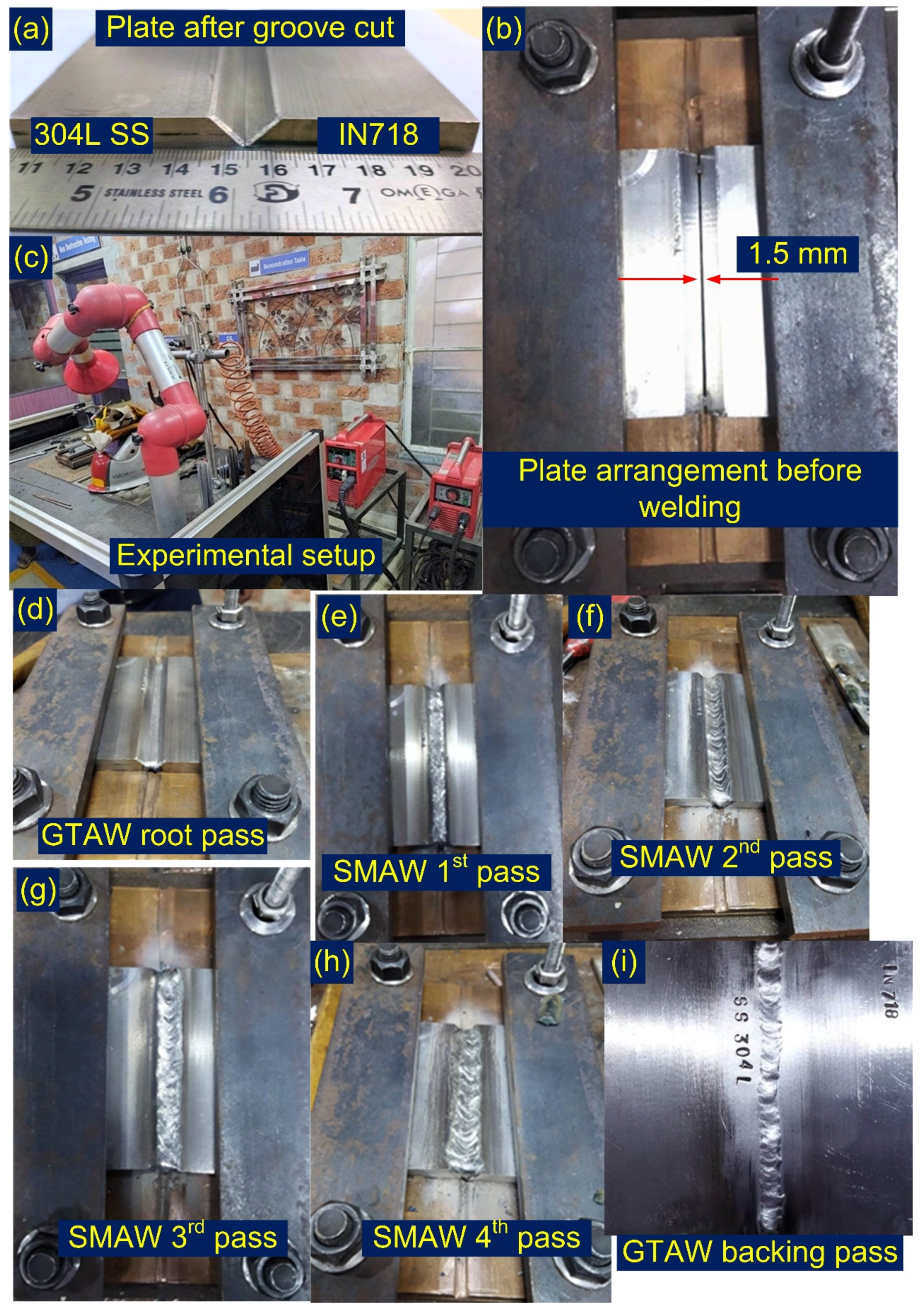
2.1. Welding Details

The multi-pass V-groove butt joint of the IN718 and 304L SS was prepared using gas tungsten arc welding (GTAW) and SMAW processes. The groove details are as follows: groove angle: 75°, root height: 1.5 mm, and root gap: 1.5 mm. The plate after groove preparation is depicted in Figure 2a. The root pass was performed using the GTAW process with ERNiCr-3 (Inconel 82) filler of diameter 1.2 mm for better accessibility of the root area and avoiding the formation of non-metallic (slag) inclusions. To prevent the oxidation and entrapment of the atmospheric gases during the root pass, pure Ar (99.99%) was used as a shielding gas and supplied at a flow rate of 15 L/min. The filling passes were performed using the SMAW process with ENiCrFe-3 filler (Inconel 182) of diameter 3.2 mm. A total of four welded passes were used to fill the groove. The backing pass was performed using the GTAW process. The welding parameters for the root pass, filling passes, and backing pass are mentioned in Table 1. The plate was fixed from both sides to control the distortion of the plate. The gap between the plate was kept at 1.5 mm, and the setup is given in Figure 2b. The welding machine (Fronius India, Model Number: Transpocket 2500; Pune, Maharashtra, India) is given in Figure 2c. The plate after root pass preparation is shown in Figure 2d. The filling SMAW passes are presented in Figure 2e–h. The plate after a GTAW backing pass is shown in Figure 2i. The welded joint was subjected to visual testing, during which, it was classified at quality level B in accordance with the requirements of EN ISO 5817.
The heat input is calculated using the following Equation (1) [27]:
H I = η 60 V I 1000 S
where HI = heat input (kJ/mm); V = arc voltage (V); I = welding current (A); S = travel speed (mm/min); and η = thermal efficiency and was considered as 0.6 for the GTAW root pass and 0.8 for the SMAW filling passes. The total heat input was 1.329 kJ/mm.

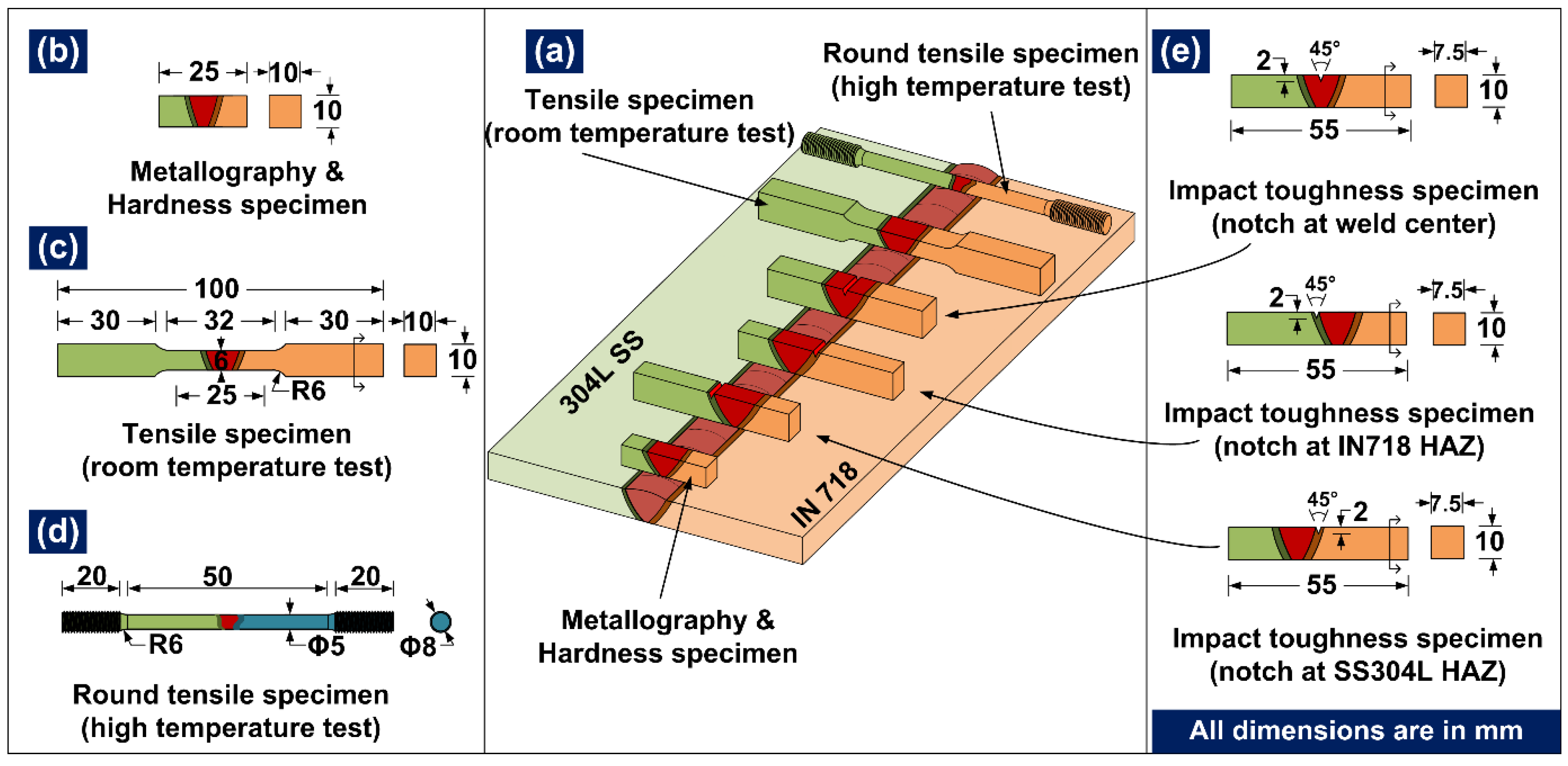
2.2. Metallographic and Mechanical Characterization

In order to evaluate the tensile properties, impact strength, hardness profile, and microstructure evolution for the welded joint, the specimen was cross-sectioned as per the schematic image (Figure 3a). The transverse cross-section of dimensions 25 mm × 10 mm × 10 mm (Figure 3b) was machined from the welded joint, and the top surface was grinded using a conventional grinder and after that by using SiC paper of different grit sizes from 120–1200. After SiC polishing, cloth polishing using alumina powder and distilled water was performed. The transverse cross-section was metallographically characterized after electrolytic etching (weld metal, IN718 HAZ, and base metal) and etching with aqua regia (1HNO3 + 3HCl) (304L SS HAZ and base metal) using the optical microscope (Make: Leica, Model: DMC4500, Leica Microsystems GmbH, Wetzlar, Germany) and scanning electron microscope (SEM) (Carls Zeiss Ultra plus and FEI Quanta 200, Carl Zeiss Microscopy Deutschland GmbH, Oberkochen, Germany). An energy-dispersive X-ray spectrometer (EDS, Carl Zeiss, Oberkochen, Germany) was used to analyze the elemental diffusion across the interface and chemical composition of the segregated phases. The tensile specimen (Figure 3c) was machined as per the AWS B4.0 standard, and the test was conducted at room temperature with a nominal extension rate of 1 mm/min (Instron 5980 of 100 kN capacity, Instron, Norwood, MA, USA). High-temperature tensile rupture behavior was studied at a temperature of 600 °C and a head speed of 1 mm/min. The specimen dimensions are presented in Figure 3d. The impact strength of the welded joint was measured at room temperature by performing the Charpy V-notch impact test. The test was conducted on a standard specimen (ASTM E23) using an impact tester (FIT-400-ASTM-D, Fine Testing Machines Pvt. Ltd., Miraj, India) of capacity 400 J (Figure 3e). The tensile- and impact-tested specimen was examined using SEM. The sample prepared for metallographic characterization was also used for the hardness profile. The hardness indent was taken using a Vicker’s Microhardness Tester (Mitutoyo, Model: Autovick HM-200, Mitutoyo, Kawasaki, Tokyo, Japan) for an indent load and dwell time of 500 g and 15 s, respectively.

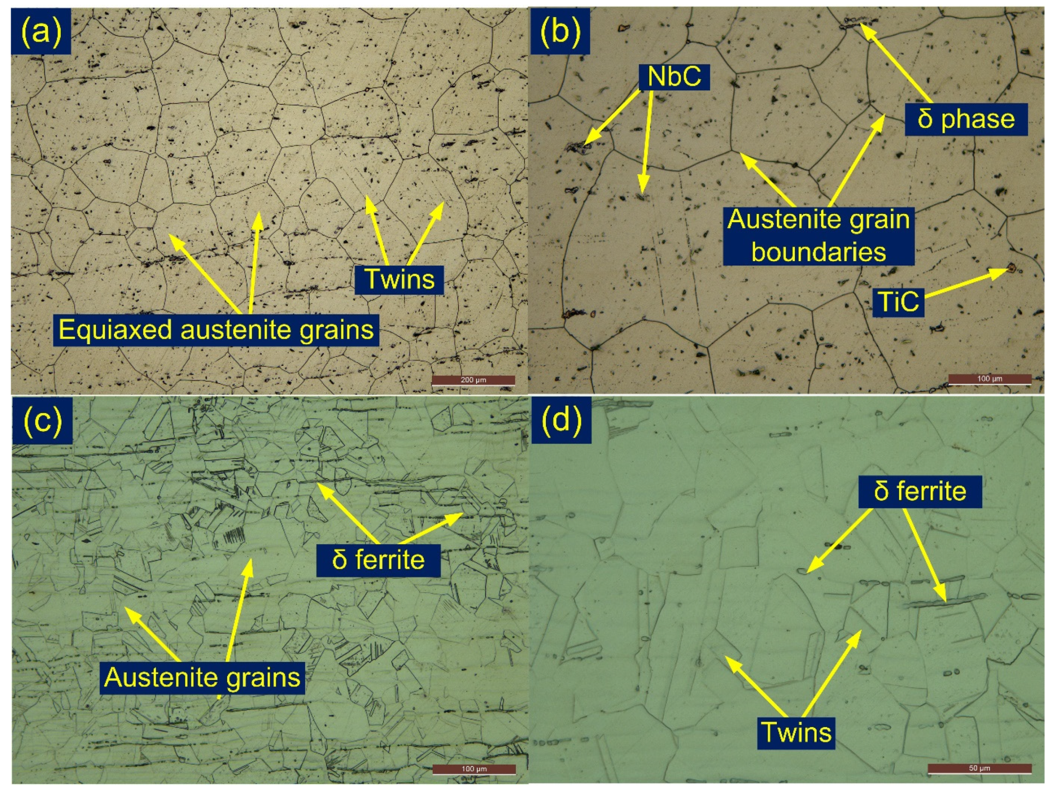
3. Results and Discussion

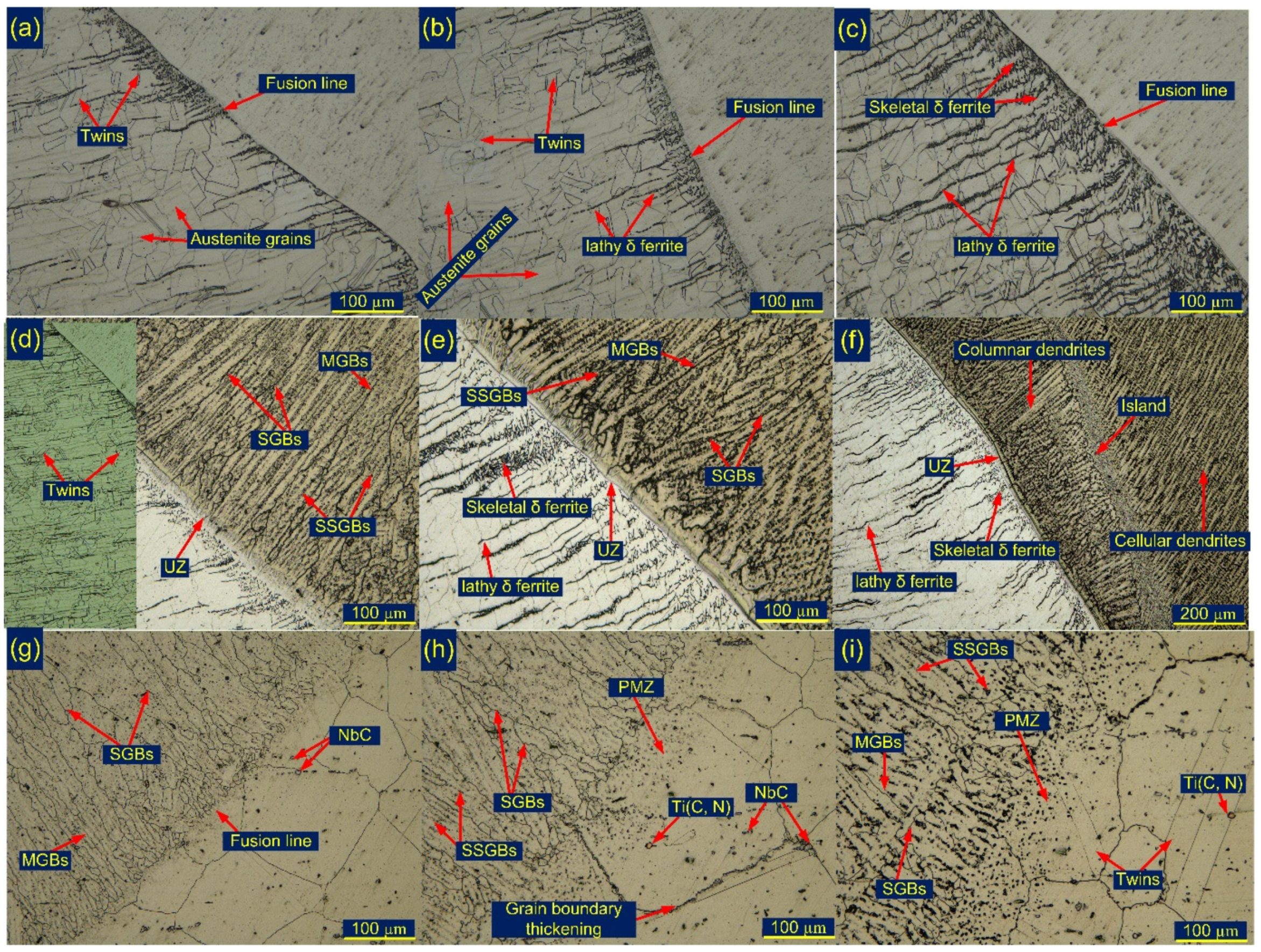
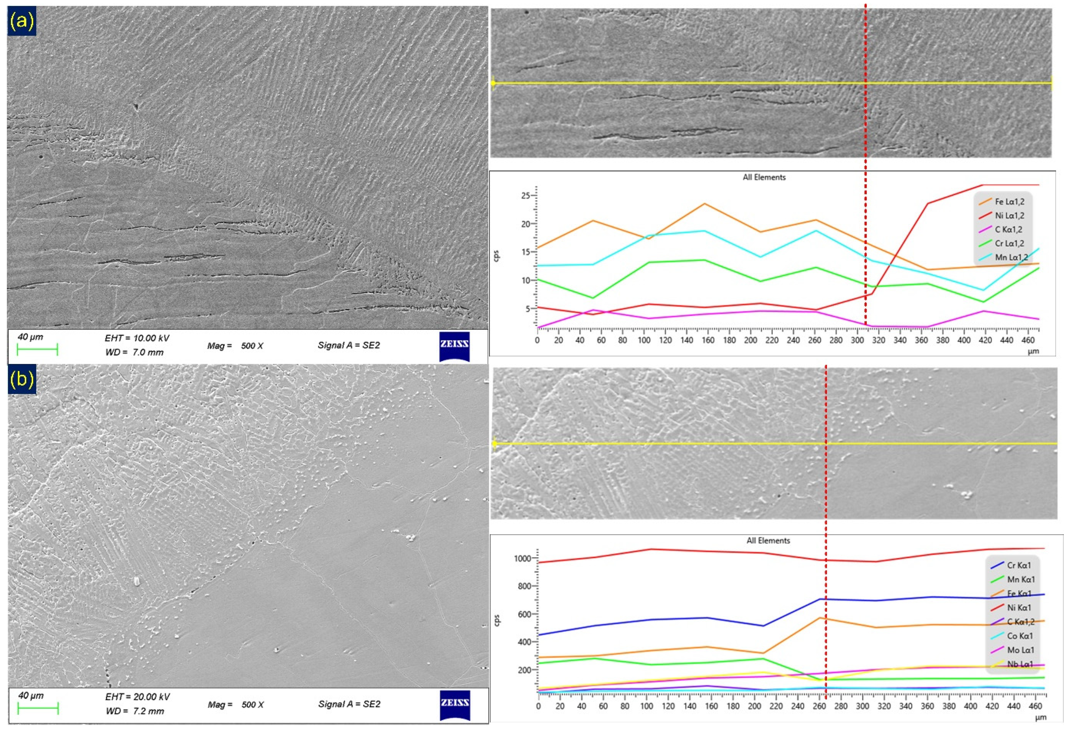
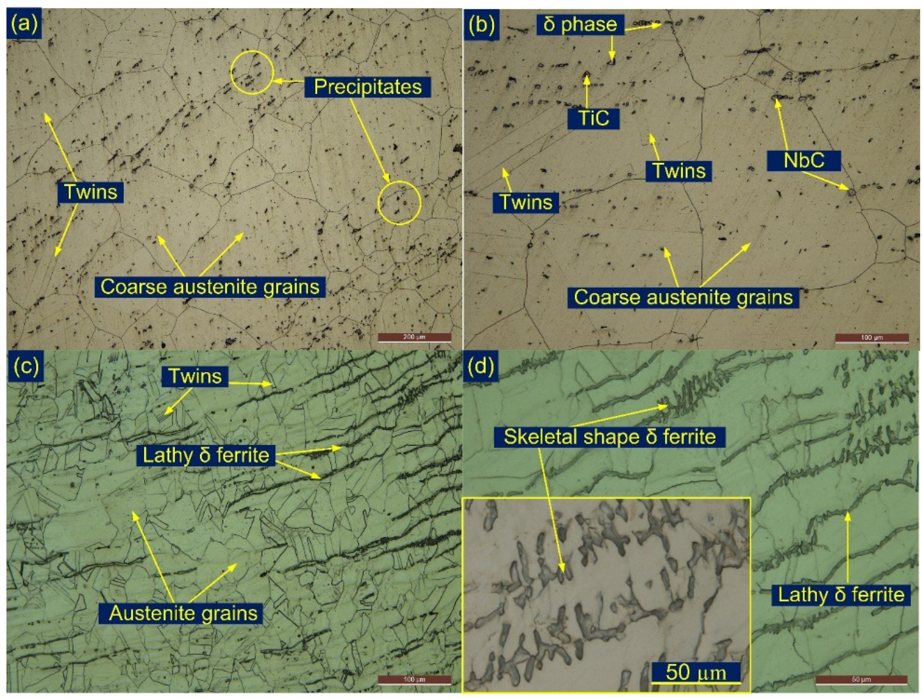
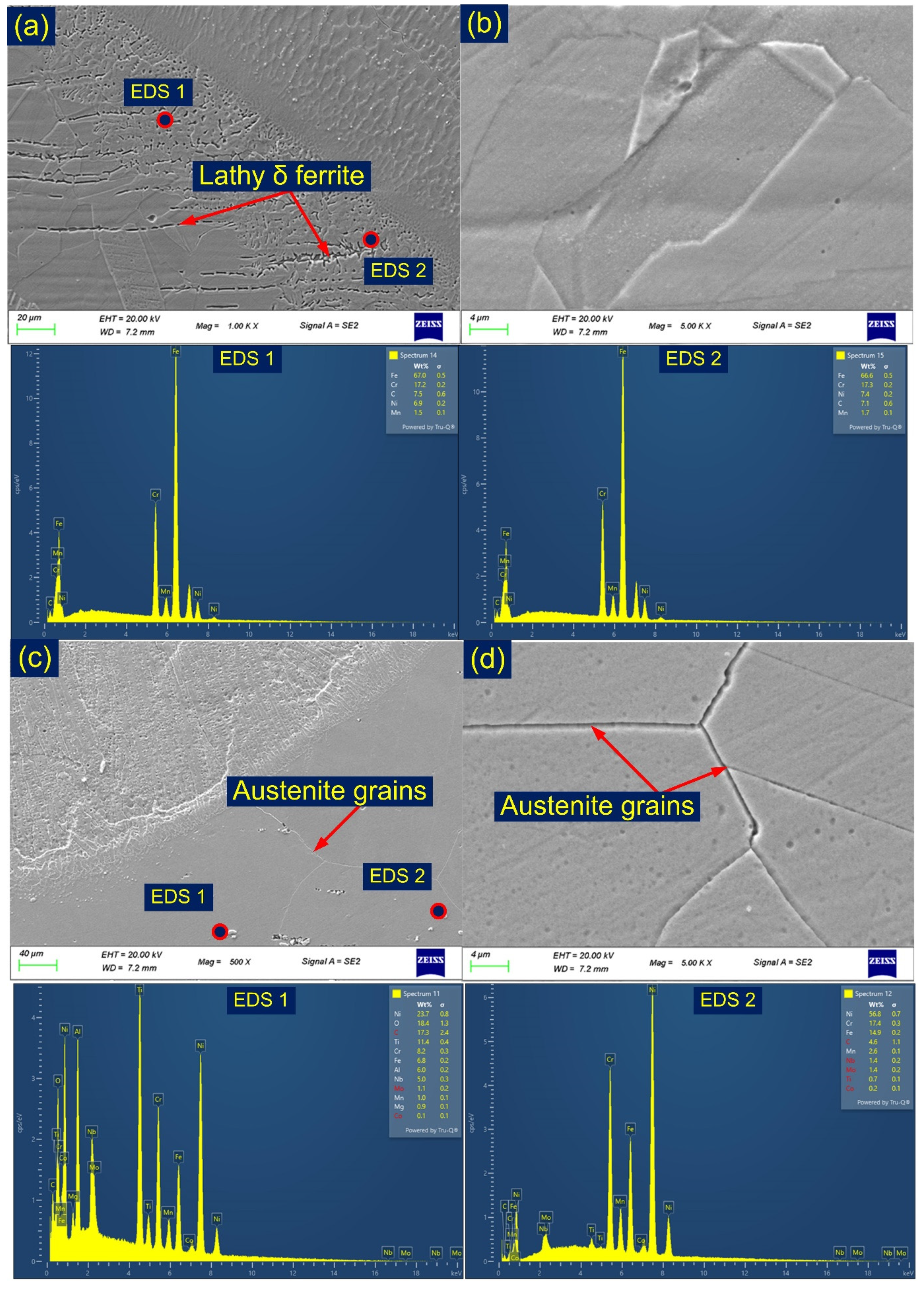
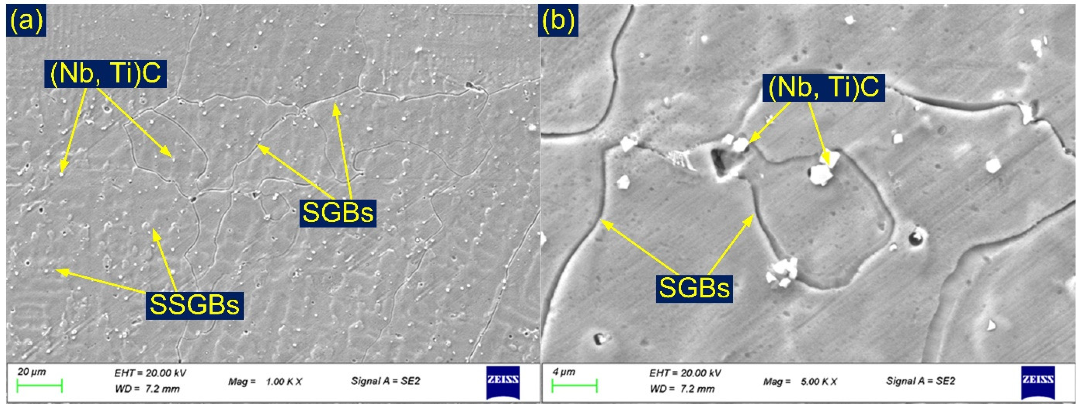
3.1. Interface and Heat-Affected Zone

The microstructure feature of the weldments is described by weld metal (WM), unmixed zone (UZ), partially melted zone (PMZ), interface, and heat-affected zone (HAZ). The microstructure of the UZ, PMZ, HAZ, and interface can be observed from Figure 4. No apparent porosity or cracking is witnessed at the interface of the ENiCrFe-3 filler weld/304L SS and the ENiCrFe-3 filler weld/IN718 alloy as depicted in Figure 4. The interface of the ENiCrFe-3 filler weld/304L SS shows a higher density of the lathy and skeletal δ ferrite (Figure 4a–c). A higher density of the lathy and skeletal δ ferrite in 304l SS HAZ was witnessed corresponding to the root pass (Figure 4c) rather than the filling passes (Figure 4a,b). The interface area after etching with electrolytic solution is presented in Figure 4d–f. A very narrow bright region was distinguished in between the ENiCrFe-3 filler weld and the 304L SS as marked in Figure 4d–f. The region is considered as a UZ and formed mainly due to differences in the melting temperature and chemical composition of the 304L SS BM and the filler metal. A filler-deficient zone island is also witnessed from Figure 4f. The weld metal near the interface has columnar and cellular grains. The weld metal of the Ni-based filler mainly shows the solidified grain boundaries (SGBs), solidified sub-grain boundaries (SSGBs), and migrated grain boundaries (MGBs) along with the segregation of the alloying elements present in the filler metal [28]. The weld near the interface consists of the SGBs, SSGBs, and MGBs as marked in the optical image (Figure 4d–f). An interface of IN718 and ENiCRFe-3 filler weld was also free from porosity or cracking as given in Figure 4g–i. The interface shows a shared grain in the weld metal and the IN718 BM (Figure 4g). A narrow region of the partially melted zone is witnessed from the optical image as marked in Figure 4h. The grain boundaries and element segregation along the boundaries and in the PMZ are seen from the optical image. The weld metal corresponding to the root region (Figure 4i) shows a higher density of the segregation than the filling passes, which might be due to the multi-pass heating effect of the filling passes. The grain boundary thickening in the IN718 HAZ and in the PMZ is also witnessed from Figure 4h.
An SEM image corresponding to the interface of the weld metal and the BMs is depicted in Figure 5a,b. The interface, along 304L SS, consists of a considerable unmixed zone (UZ), columnar dendrites in the weld metal, and lathy δ ferrite in the 304L SS HAZ (Figure 5a). A sharp compositional gradient for elements Fe, Ni, Cr, and Mn exists along the interface (Figure 5a). The line map confirms the movement of the Ni from the weld metal to the 304L SS while Fe moved from the 304L SS to the weld metal. No measurable diffusion was observed for Cr. The interface of the IN718 has a partially melted zone, columnar dendrites in the weld metal, and a higher density of the secondary phases in the region of the PMZ. A minor change in element composition was observed across the interface as a result of small variations in the chemical composition of the weld metal and the IN718 alloy. A small change in chemical composition was noticed for Cr, Fe, Co, and Mn (Figure 5b).
The heat-affected zone (HAZ) microstructure for the IN718 alloy and 304L SS is given in Figure 6a–d. Grain growth in the HAZ is witnessed from the optical image. In the IN718 alloy HAZ, the grain size was measured at 198 ± 40 µm, which was higher than the IN718 BM. In a similar fashion, the grain size in the 304L SS HAZ was estimated higher than the 304L SS BM, and it was 49 ± 11 µm. Generally, C shows the higher diffusivity in a solid Ni alloy matrix and results in the diffusion of C from the weld metal to the IN718 HAZ. The diffused C may combine with alloying elements such as Cr and Mo present in IN718 BM and leads to the formation of carbides in addition to those already existing in IN718 BM. The higher density of the precipitates is also witnessed from Figure 6a,b. Cortés et al. [29] reported that the phase present in the IN718 HAZ was enriched with Nb, Ti, Mo, and C. The phases might be Nb- and Ti-rich (Nb, Ti), C, or δ phase (Figure 6b). The lathy δ ferrite in the 304L SS HAZ is witnessed from the optical image (Figure 6c). The density was much higher near the fusion line and reduces as it moves away from it (Figure 6c). The image captured near the fusion line was also beautified by the skeletal shape δ ferrite (Figure 6d).
The region of the 304L SS HAZ near the fusion line has a large density of lathy and skeletal δ ferrite as marked in Figure 7a. The region shows the grain growth as an effect of the multi-pass welding cycle. Twins are also witnessed from the SEM image (Figure 7a,b). The EDS of the HAZ shows the major concentration of the Fe, Cr, Ni, C, and Mn. An SEM/EDS observation has also been performed for the IN718 HAZ and presented in Figure 7c,d. The major elements observed in the HAZ are Ni, Cr, Fe, Nb, Mn, Mo, and Ti. The EDS of point 1 confirms the phase of Nb and Ti in the IN718 HAZ.

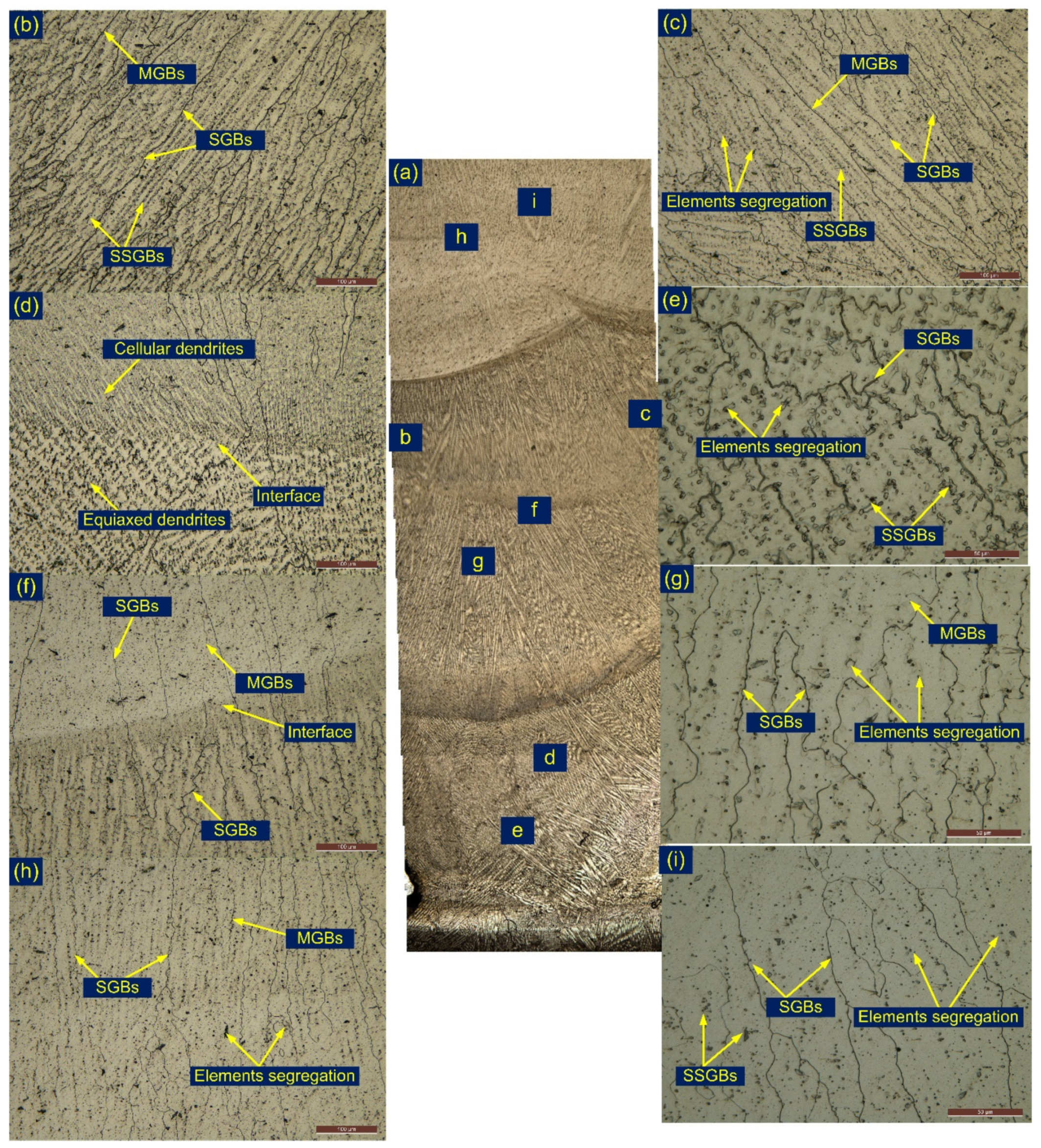
3.2. Inconel 182 Filler Weld

Figure 8a displays the cross-section of the deposited metal and various marked regions for detailed characterization. The columnar and cellular types of the grains are seen from the optical image. The weld microstructure is fully austenitic with a high Ni content. The region near the fusion line has mainly coarse columnar grains and consists of grain boundaries. The segregation of the alloying elements along the intergranular and interior of grains is also witnessed (Figure 8b,c). The major precipitates in the ENiCrFe-3 filler were reported as NbC and Ti(C, N) of globular and cubic morphology [30,31]. ENiCrFe-3 has a considerable amount of Nb content which leads to the formation of the brittle NbC phase. However, the higher weight percentage of the Fe in the ENiCrFe-3 filler limits the solubility of the Nb in the austenitic matrix. That favors the partitioning of the Nb within the area of the dendrites and results in the formation of NbC precipitates. The weld metal corresponding to the root area has mainly columnar and cellular grains with a close spacing of the dendrites compared to the center region of the weld metal. The heating effects of the filling and top passes have also seen a significant effect on the austenitic microstructure, and it shows the higher density of the secondary phases along SGBs and SSGBs (Figure 8e). Changes in the solidification mode in the root area and shared grains are witnessed from Figure 8d. The weld metal corresponding to the filling pass has also columnar and cellular grains, but the density of the carbides phase was observed to be lower than the weld metal in the root region (Figure 8f,g). The shard’s grain and varying morphology in the microstructure of the weld metal is also witnessed from Figure 8f. The weld metal corresponding to the top pass is depicted in Figure 8h,i and shows similar morphology to the filling passes. Weld metals have grain boundaries (SGBs, SSGBs, and MGBs) and element segregation along the inter-dendritic spaces. The austenitic filler weld shows the distribution of the secondary phases along the boundaries and within the matrix in the SEM image (Figure 9a,b). The boundaries are marked in Figure 9a. Precipitates of different size and morphology are distributed along the SGBs/SSGBs (Figure 9b). The EDS of the white particle shows the major weight percentage of Ti (8.5 wt.%), Nb (30.52 wt.%), Cr (15.42 wt.%), Ni (37.52 wt.%), and Fe (4.25 wt.%). The particles were confirmed as the secondary phases of Ti and Nb of type MX.

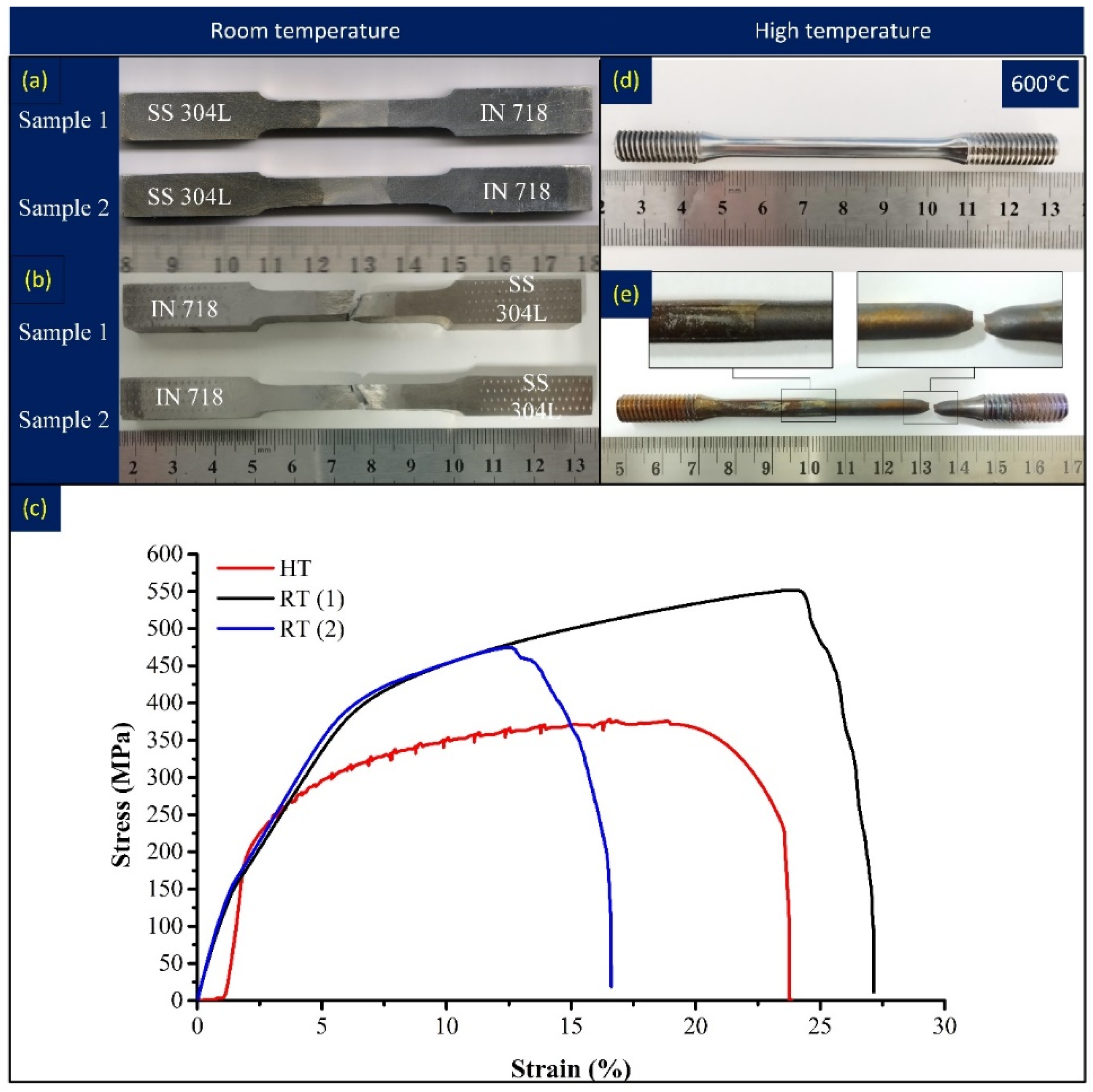
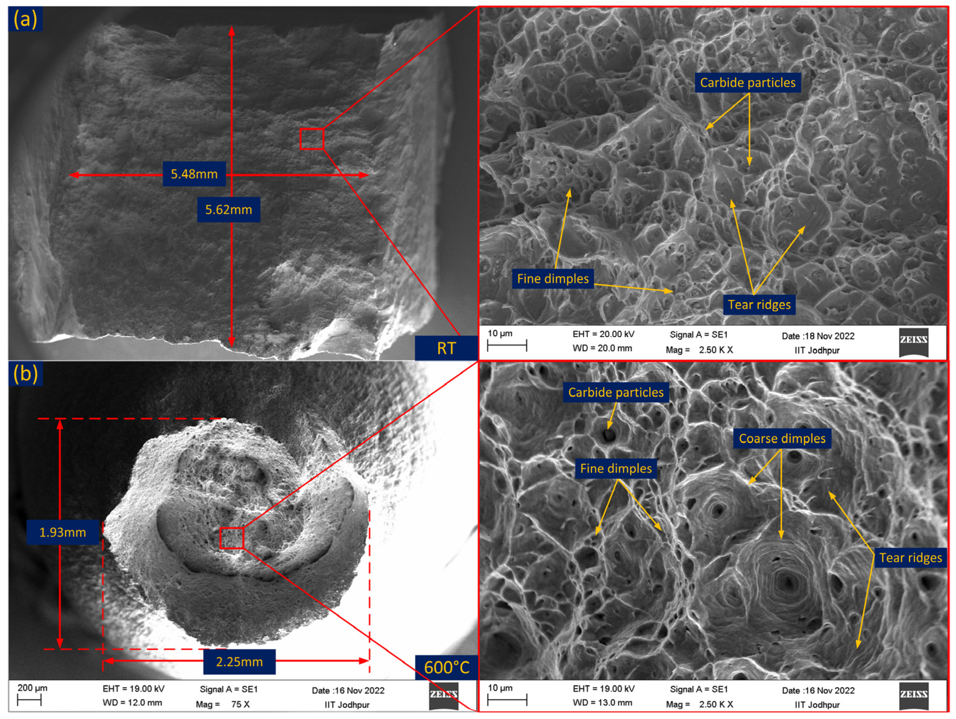
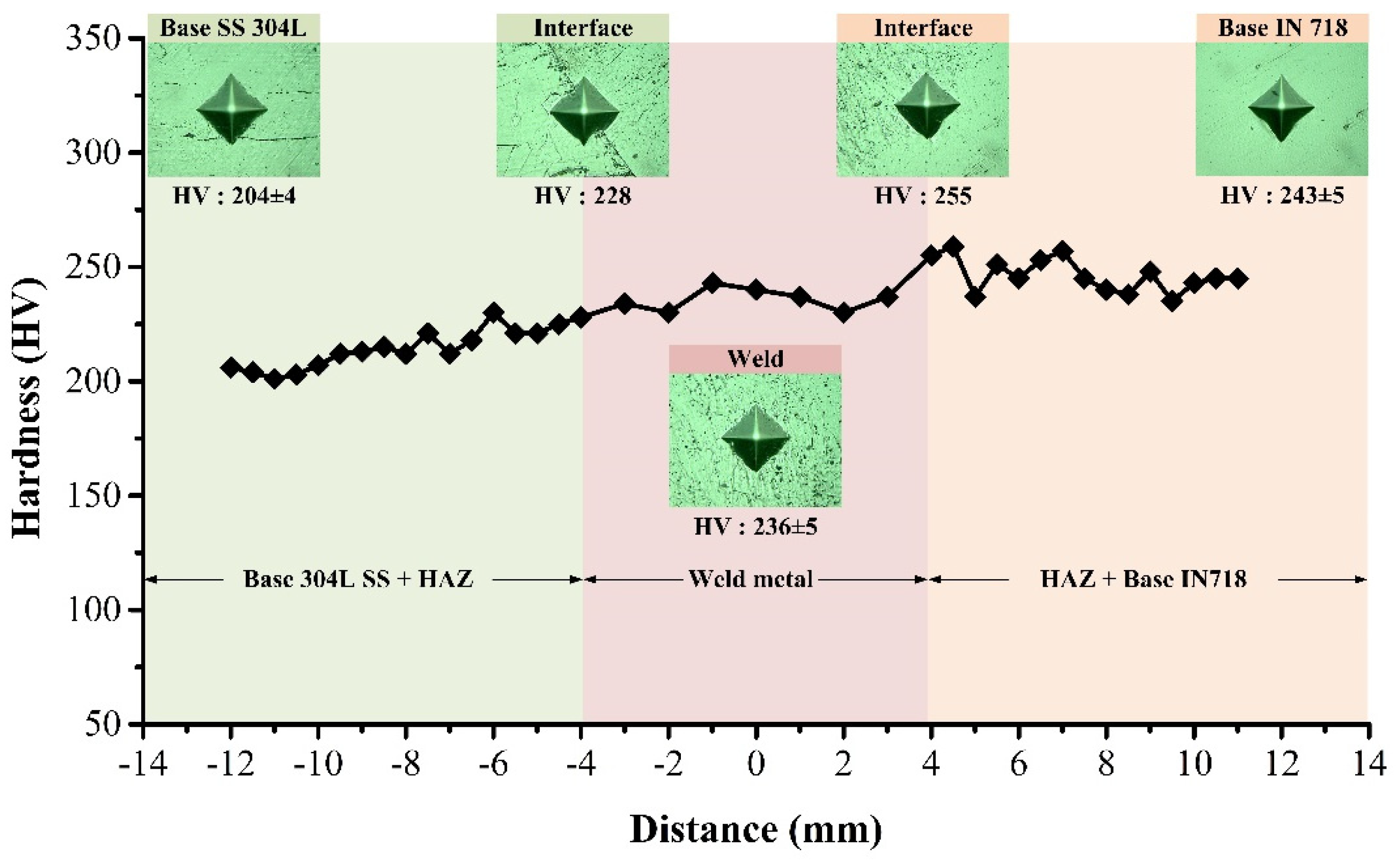
3.3. Mechanical Testing

The sample prepared to estimate the tensile behavior of the welded joint is given in Figure 10a. The test coupons failed in the weld metal without any evident neck formation as witnessed from Figure 10b. The strength of the welded joint was 474 MPa and 551 MPa for test coupon 1 and test coupon 2, respectively (Table 2). The failed sample of weld metal instead of base metal shows the inferior properties of weld compared to base metals. The failure behavior was not consistent with the hardness plot as poor hardness was measured in 304L SS BM, and failure was also expected in the region of the 304L SS BM instead of the weld metal. The failure of the test coupons from the weld metal might be due to the segregation of the Nb particle at the inter-dendritic spaces of the austenitic weld metal which results in the formation of a brittle secondary NbC phase which facilitates crack nucleation during the loading. Cortés et al. [29] also observed similar tensile behavior for the GTAW joint of IN718 alloy. The evolution of the NbC phases reduces the Nb content required to enhance the strength of the weld metal [32]. The stress–strain behavior for the room temperature tensile-tested coupons is given in Figure 10c. The % elongations were 17% and 27% for test coupons 1 and 2, respectively. High-temperature tensile rupture behavior of the welded joint was studied at a temperature of 600 °C. The test coupons before and after the test are presented in Figure 10d,e. The tensile test showed the failure of 304L SS BM at a temperature of 600 °C with a tensile strength value of 377 MPa, which was lower than the strength of the welded joint obtained at room temperature. At higher magnifications, crack initiation all around the fusion boundary is also observed. The % elongation was measured at 24%, and a clear cup-cone formation before fracture was also witnessed (Figure 10e). The stress–strain plot is included in Figure 10c.
A fracture surface study of the tensile-tested specimen was also carried out and displayed in Figure 11a,b. The sample tested at room temperature shows the mixed mode of the fracture and surface and reveals fine dimples, tear ridges, and carbide particles (Figure 11a). The dimension of the fractured specimen at the tip point is mentioned in Figure 11a. The ductile dimple-dominated fracture was observed for the sample tested at a high temperature (Figure 11b). The fracture surface reveals the presence of dimples of varying sizes, tear ridges, and carbide particles. The average diameter at the fracture tip point was 2.09 mm.
The average hardness of the ENiCrFe-3 filler weld was 236 ± 5 HV, which was higher than the 304L SS BM (204 ± 4 HV) but lower than the IN718 BM (243 ± 5 HV). A negligible hardness variation was seen for the weld metal (Figure 12). However, near the interface on both sides, a significant change in hardness was observed. The peak hardness of 255 HV was measured near the ENiCrFe-3 filler weld and the IN718 BM interface. That might be due to the segregation of the Nb, Ni, and C elements. The interface of the 304L BM and the weld metal showed a hardness of 228 HV, which was lower than the weld metal but higher than the 304L SS BM. The variation in hardness along the weldments is governed by elemental diffusion, macrosegregation, and heating effects as a result of multi-pass, complex welding thermal cycles. The average hardnesses of the 304L SS HAZ and the IN718 HAZ were 221 HV and 249 HV, respectively.
A room temperature notch Charpy impact toughness test was conducted for the weld metal and HAZ of IN718 alloy and 304L SS. The test coupons after the notch preparation and after the Charpy impact test are presented in Table 3. It was inferred from the test results that the average impact toughness of the weld metal is lower than the HAZ, and also the sample failed into two halves during impact loading without any significant plastic deformation. The impact toughness of the weld metal was 109 J. A significant variation in impact toughness was observed from the test results. The impact toughness of the 304L SS HAZ and IN718 alloy HAZ was 340 J and 182 J, respectively. The sample of the 304L SS HAZ showed significant yielding before fracture; however, the sample failed into two halves. The crack initiation in the root region was also noticed. The sample of the IN718 HAZ also showed yielding, but the impact toughness value was measured lower than the 304L SS HAZ. That might be due to the presence of the carbide phases such as NbC and Ti(C, N). The poorer impact toughness of the weld than the HAZ might be due to the presence of the brittle NbC phase in the weld metal as discussed in the metallographic section. The brittle phases served as crack nucleation sites during the loading and resulted in poor impact toughness [33]. The poor impact toughness for the ENiCrFe-3 filler weld has also been observed in previously published works [7,34].

4. Conclusions

The article describes the morphology and mechanical properties of a dissimilar welded joint (between Inconel 718 nickel alloy and 304L austenitic stainless steel) formed by combined arc welding technology with two processes: GTAW and SMAW. The welded joint was subjected to a detailed microstructural analysis and tests: tensile tests at room temperature and at 600 °C, hardness measurements, and impact tests. The main conclusions can be drawn as follows:
1. The welding procedure used allowed for the fabrication of a sound welded joint, which, during visual testing, was classified at quality level B in accordance with the requirements of EN ISO 5817.
2. The correctness of the proposed manufacturing procedure was also confirmed by metallographic microscopic examinations. In the areas of the weld, interface, and heat-affected zones, no welding imperfections were found: porosity, cracks, and non-metallic and metallic inclusions.
3. The weld is characterized by a fully austenitic structure with the Nb- and Ti-rich carbide phases along the inter-dendritic spaces, which strongly affects the mechanical properties of the joint. The effect of multi-pass welding is an increase in the density of the secondary phases in the lower parts of the joint (root area).
4. Significant differences in the morphologies and chemical composition of the zones between the weld and the base materials were stated. From the side of the 304L austenitic stainless steel, a type B fusion boundary with a distinct fusion line was found. The diffusion of Ni from the weld metal to the 304L stainless steel and the movement of Fe in the opposite direction was observed, but no changes in the Cr content were noticed. Additionally, higher densities of the lathy and skeletal δ ferrite in the 304L SS HAZ were witnessed corresponding to the root pass than the filling passes. The morphology of the area between the weld and the Inconel 718 alloy is different (type A fusion boundary). In this case, no significant changes in the distribution of alloying elements between the weld and the Ni alloy were found.
5. A comparison of the tensile test results conducted at different temperatures shows that in the standard test, the joint fractured in the weld (474 and 551 MPa), while in the tests performed at 600 °C, it fractured in the austenitic steel (377 MPa). The lower mechanical properties of the weld during room temperature tests may result from the depletion of this area in Nb resulting from the formation of a brittle secondary phase (NbC) that promotes crack nucleation under tensile loading.
6. Joint hardness is limited to values in the range of 200 to 250 HV for 304L steel and Inconel 718 alloy BM, respectively. The weld is characterized by an intermediate hardness, approx. 236 HV, while an increase in hardness is noticeable in the fusion line zones, especially on the side of the Ni alloy, to the value of 255 HV. Such an increase in hardness may result from the segregation of the Nb, Ni, and C elements.
7. The impact toughness of the weld metal was significantly lower than the base metals (109 J vs. 340 J for 304L steel and 182 J for Ni alloy). The probable cause of this situation is the evolution of the NbC phase along the inter-dendritic spaces, demonstrated by metallographic studies.
8. The described welding manufacturing technology can be used for the qualification of welding procedures of dissimilar joints intended for operation in high temperatures in various industries.

Author Contributions

Conceptualization, S.S., S.M.P., A.Ś., N.K., D.F. and C.P.; methodology, S.S., S.M.P., M.L., N.K., D.F. and C.P; formal analysis, D.F., A.Ś., G.R., M.L., D.F. and C.P.; investigation, S.S., S.M.P., A.Ś., N.K., M.L. and C.P.; resources, S.S., S.M.P., A.Ś., N.K., D.F. and C.P.; data curation, S.S., S.M.P., A.Ś., N.K., M.L. and C.P.; writing—original draft preparation, S.S., S.M.P., A.Ś., G.R., N.K., M.L., D.F. and C.P.; writing—review and editing, S.S., S.M.P., A.Ś., G.R., N.K., M.L., D.F. and C.P.; visualization, S.S., S.M.P., G.R., N.K., M.L. and C.P.; supervision, D.F. and C.P.; project administration, D.F. and C.P. All authors have read and agreed to the published version of the manuscript.

Funding

This research received no external funding.

Institutional Review Board Statement

Not applicable.

Informed Consent Statement

Not applicable.

Data Availability Statement

Not applicable.

Conflicts of Interest

The authors declare no conflict of interest.

References

  1. Chen, H.C.; Pinkerton, A.J.; Li, L. Fibre laser welding of dissimilar alloys of Ti-6Al-4V and Inconel 718 for aerospace applications. Int. J. Adv. Manuf. Technol. 2011, 52, 977–987. [Google Scholar] [CrossRef]
  2. Dak, G.; Sirohi, S.; Pandey, C. Study on microstructure and mechanical behavior relationship for laser-welded dissimilar joint of P92 martensitic and 304L austenitic steel. Int. J. Press. Vessel. Pip. 2022, 196, 104629. [Google Scholar] [CrossRef]
  3. Mortezaie, A.; Shamanian, M. An assessment of microstructure, mechanical properties and corrosion resistance of dissimilar welds between Inconel 718 and 310S austenitic stainless steel. Int. J. Press. Vessel. Pip. 2014, 116, 37–46. [Google Scholar] [CrossRef]
  4. Jamrozik, W.; Górka, J.; Kik, T. Temperature-Based Prediction of Joint Hardness in TIG Welding of Inconel 600, 625 and 718 Nickel Superalloys. Materials 2021, 14, 442. [Google Scholar] [CrossRef]
  5. Kumar, N.; Pandey, C.; Kumar, P. Dissimilar Welding of Inconel Alloys With Austenitic Stainless-Steel: A Review. J. Press. Vessel Technol. 2023, 145, 011506. [Google Scholar] [CrossRef]
  6. Di Schino, A.; Kenny, J.M.; Mecozzi, M.G.; Barteri, M. Development of high nitrogen, low nickel, 18%Cr austenitic stainless steels. J. Mater. Sci. 2000, 35, 4803–4808. [Google Scholar] [CrossRef]
  7. Shah Hosseini, H.; Shamanian, M.; Kermanpur, A. Characterization of microstructures and mechanical properties of Inconel 617/310 stainless steel dissimilar welds. Mater. Charact. 2011, 62, 425–431. [Google Scholar] [CrossRef]
  8. Bhanu, V.; Fydrych, D.; Gupta, A.; Pandey, C. Study on Microstructure and Mechanical Properties of Laser Welded Dissimilar Joint of P91 Steel and INCOLOY 800HT Nickel Alloy. Materials 2021, 14, 5876. [Google Scholar] [CrossRef]
  9. Sridhar, R.; Devendranath Ramkumar, K.; Arivazhagan, N. Characterization of microstructure, strength, and toughness of dissimilar weldments of inconel 625 and duplex stainless steel SAF 2205. Acta Metall. Sin. Engl. Lett. 2014, 27, 1018–1030. [Google Scholar] [CrossRef] [Green Version]
  10. Devendranath Ramkumar, K.; Dev, S.; Saxena, V.; Choudhary, A.; Arivazhagan, N.; Narayanan, S. Effect of flux addition on the microstructure and tensile strength of dissimilar weldments involving Inconel 718 and AISI 416. Mater. Des. 2015, 87, 663–674. [Google Scholar] [CrossRef]
  11. Cortés, R.; Rodríguez, N.K.; Ambriz, R.R.; López, V.H.; Ruiz, A.; Jaramillo, D. Fatigue and crack growth behavior of Inconel 718–AL6XN dissimilar welds. Mater. Sci. Eng. A 2019, 745, 20–30. [Google Scholar] [CrossRef]
  12. Gomes, D.D.A.; Castro, J.A.; Xavier, C.R.; Cardoso Lima, C.A. Analysis of residual stress by the hole-drilling method and hardness in dissimilar joints of austenitic stainless steel AISI 316L and inconel 718 alloy by autogenous GTAW process. Mater. Res. 2019, 22, e20180844. [Google Scholar] [CrossRef]
  13. Klett, J.; Hassel, T. Influence of Stick Electrode Coating’s Moisture Content on the Diffusible Hydrogen in Underwater Wet Shielded Metal Arc Welding. Adv. Mater. Sci. 2020, 20, 27–37. [Google Scholar] [CrossRef]
  14. Tomków, J.; Świerczyńska, A.; Landowski, M.; Wolski, A.; Rogalski, G. Bead-on-Plate Underwater Wet Welding on S700MC Steel. Adv. Sci. Technol. Res. J. 2021, 15, 288–296. [Google Scholar] [CrossRef]
  15. Dak, G.; Pandey, C. Study on effect of weld groove geometry on mechanical behavior and residual stresses variation in dissimilar welds of P92/SS304L steel for USC boilers. Arch. Civ. Mech. Eng. 2022, 22, 140. [Google Scholar] [CrossRef]
  16. Kumar, A.; Pandey, C. Development and Evaluation of Dissimilar Gas Tungsten Arc-Welded Joint of P92 Steel/Inconel 617 Alloy for Advanced Ultra-Supercritical Boiler Applications. Metall. Mater. Trans. A 2022, 53, 3245–3273. [Google Scholar] [CrossRef]
  17. Ramkumar, K.D.; Kumar, P.S.G.; Krishna, V.R.; Chandrasekhar, A.; Dev, S.; Abraham, W.S.; Prabhakaran, S.; Kalainathan, S.; Sridhar, R. Influence of laser peening on the tensile strength and impact toughness of dissimilar welds of Inconel 625 and UNS S32205. Mater. Sci. Eng. A 2016, 676, 88–99. [Google Scholar] [CrossRef]
  18. Pavan, A.H.V.; Ravibharath, R.; Singh, K. Creep-rupture behavior of SUS 304H—IN 617 dissimilar metal welds for AUSC boiler applications. Mater. Sci. Forum 2015, 830–831, 199–202. [Google Scholar] [CrossRef]
  19. Deng, J.; Liang, Z.; Hui, S.; Zhao, Q. Aging Treatment on the Microstructures and Mechanical Properties of New Groove T92/Super 304H Dissimilar Steel Joints. High Temp. Mater. Process. 2015, 34, 425–433. [Google Scholar] [CrossRef]
  20. Zhang, Y.; Cai, Z.; Han, C.; Huo, X.; Fan, M.; Li, K.; Pan, J. Macrosegregation induced interface structure and its effect on creep failure in dissimilar metal welds between Ni-based alloy and 10% Cr martensitic steel. Mater. Sci. Eng. A 2021, 824, 141847. [Google Scholar] [CrossRef]
  21. Bhanu, V.; Gupta, A.; Pandey, C. Investigation on joining P91 steel and Incoloy 800HT through gas tungsten arc welding for Advanced Ultra Super Critical (AUSC) power plants. J. Manuf. Process. 2022, 80, 558–580. [Google Scholar] [CrossRef]
  22. Sireesha, M.; Albert, S.K.; Shankar, V.; Sundaresan, S. Comparative evaluation of welding consumables for dissimilar welds between 316LN austenitic stainless steel and Alloy 800. J. Nucl. Mater. 2000, 279, 65–76. [Google Scholar] [CrossRef]
  23. Kumar, A.; Pandey, C. Some studies on dissimilar welds joint P92 steel and Inconel 617 alloy for AUSC power plant application. Int. J. Press. Vessel. Pip. 2022, 198, 104678. [Google Scholar] [CrossRef]
  24. Ramkumar, K.D.; Arivazhagan, N.; Narayanan, S. Effect of filler materials on the performance of gas tungsten arc welded AISI 304 and Monel 400. J. Mater. 2012, 40, 70–79. [Google Scholar] [CrossRef]
  25. Ranjbar, K.; Dehmolaei, R.; Amra, M.; Keivanrad, I. Microstructure and properties of a dissimilar weld between alloy 617 and A387 steel using different filler metals. Weld. World 2018, 62, 1121–1136. [Google Scholar] [CrossRef]
  26. Li, R.B.; Yao, M.; Liu, W.C.; He, X.C. Isolation and determination for δ, γ′ and γ″ phases in Inconel 718 alloy. Scr. Mater. 2002, 46, 635–638. [Google Scholar] [CrossRef]
  27. Pandey, C.; Giri, A.; Mahapatra, M.M. On the prediction of effect of direction of welding on bead geometry and residual deformation of double-sided fillet welds. Int. J. Steel Struct. 2016, 16, 333–345. [Google Scholar] [CrossRef]
  28. Bhanu, V.; Gupta, A.; Pandey, C. Role of A-TIG process in joining of martensitic and austenitic steels for ultra-supercritical power plants -a state of the art review. Nucl. Eng. Technol. 2022, 54, 2755–2770. [Google Scholar] [CrossRef]
  29. Cortés, R.; Barragán, E.R.; López, V.H.; Ambriz, R.R.; Jaramillo, D. Mechanical properties of Inconel 718 welds performed by gas tungsten arc welding. Int. J. Adv. Manuf. Technol. 2018, 94, 3949–3961. [Google Scholar] [CrossRef]
  30. Mittal, R.; Sidhu, B.S. Microstructures and mechanical properties of dissimilar T91/347H steel weldments. J. Mater. Process. Technol. 2015, 220, 76–86. [Google Scholar] [CrossRef]
  31. Cao, J.; Gong, Y.; Zhu, K.; Yang, Z.G.; Luo, X.M.; Gu, F.M. Microstructure and mechanical properties of dissimilar materials joints between T92 martensitic and S304H austenitic steels. Mater. Des. 2011, 32, 2763–2770. [Google Scholar] [CrossRef]
  32. Hinojos, A.; Mireles, J.; Reichardt, A.; Frigola, P.; Hosemann, P.; Murr, L.E.; Wicker, R.B. Joining of Inconel 718 and 316 Stainless Steel using electron beam melting additive manufacturing technology. Mater. Des. 2016, 94, 17–27. [Google Scholar] [CrossRef] [Green Version]
  33. Thakare, J.G.; Pandey, C.; Mahapatra, M.M.; Mulik, R.S. An assessment for mechanical and microstructure behavior of dissimilar material welded joint between nuclear grade martensitic P91 and austenitic SS304 L steel. J. Manuf. Process. 2019, 48, 249–259. [Google Scholar] [CrossRef]
  34. Bhanu, V.; Pandey, C.; Gupta, A. Dissimilar joining of the martensitic grade P91 and Incoloy 800HT alloy for AUSC boiler application: Microstructure, mechanical properties and residual stresses. CIRP J. Manuf. Sci. Technol. 2022, 38, 560–580. [Google Scholar] [CrossRef]
Figure 1. Optical image at low and high magnification (a,b) Inconel 718, (c,d) 304L SS.
Metals 13 00014 g001
Figure 2. (a) Plate after groove preparation, (b) arrangement of the plate before welding, (c) welding machine setup, (d) plate after GTAW root pass, (eh) SMAW filling passes, (i) backing GTAW pass.
Metals 13 00014 g002
Figure 3. (a) Schematic showing the extraction of test coupons from a welded plate, (b) test coupon for metallographic study, (c) test coupon of room-temperature tensile test, (d) test coupon for high-temperature tensile test, (e) test coupons for Charpy impact testing of weld metal and HAZ.
Metals 13 00014 g003
Figure 4. Micrograph of the interface region of the 304L SS side BM after etching with aqua regia (ac); after electrolytic etching (df); interface on the side of IN718 BM (gi).
Metals 13 00014 g004
Figure 5. Interface and line map (a) across the interface of 304L SS, (b) across the interface of IN718 alloy.
Metals 13 00014 g005
Figure 6. HAZ of IN718 (a,b); 304L SS (c,d).
Metals 13 00014 g006
Figure 7. (a,b) Interface and HAZ of 304L SS along with EDS results, (c,d) interface and HAZ of IN718 alloy along with EDS results.
Metals 13 00014 g007
Figure 8. (a) Cross-sectional view of the weld metal, (b,c) weld metal near the fusion line, (d,e) root area of the weld metal, (f,g) center region of the weld metal corresponding to filling pass, (h,i) top region of the weld metal.
Metals 13 00014 g008
Figure 9. (a,b) ENiCrFe-3 filler weld metal.
Metals 13 00014 g009
Figure 10. (a) Specimen before fracture, (b) after fracture, (c) stress–strain plot of welded joint, (d) high-temperature tensile specimen before fracture, (e) after fracture.
Metals 13 00014 g010
Figure 11. SEM image of the fractured tensile specimen tested at (a) room temperature (RT), (b) at 600 °C (HT).
Metals 13 00014 g011
Figure 12. Hardness distribution across dissimilar weldment.
Metals 13 00014 g012
Table 1. Welding parameters for root pass and filling passes.
Welding passesWelding Process Filler Metal Welding Current (A)Arc Voltage (V)Welding Speed (mm/s)Heat Input for Each Pass (kJ/mm)Total Heat Input (kJ/mm)
Root passGTAWERNiCr-3~115~9.81.670.4040.404
Filling passes 1SMAWENiCrFe-3~90~6.83.000.1630.775
Filling passes 2SMAWENiCrFe-3~90~6.82.370.206
Filling passes 3SMAWENiCrFe-3~90~6.82.050.238
Filling passes 4SMAWENiCrFe-3~90~7.03.000.168
Backing passGTAWERNiCr-3~100~7.53.000.1500.150
Table 2. Tensile test results of test coupons tested at room temperature and high temperature.
Tensile TestUltimate Tensile Strength (MPa)Elongation (%)Fracture Location
Room-temperature tensile testTest coupon 147417Weld metal
Test coupon 255127Weld metal
High-temperature tensile test (600 °C)Test coupon 137724304L SS BM
Table 3. Impact test specimen and test results.
Metals 13 00014 i001
Disclaimer/Publisher’s Note: The statements, opinions and data contained in all publications are solely those of the individual author(s) and contributor(s) and not of MDPI and/or the editor(s). MDPI and/or the editor(s) disclaim responsibility for any injury to people or property resulting from any ideas, methods, instructions or products referred to in the content.

