
SiC-Based Composite Material Reinforced with Molybdenum Wire

1
Osipyan Institute of Solid State Physics of the Russian Academy of Sciences, Ac. Osipyan Str. 2, 142432 Chernogolovka, Russia
2
Department of Arctical Programs, Bauman Moscow State Technical University, 2nd Baumanskaya Street 5, 105005 Moscow, Russia
*
Author to whom correspondence should be addressed.
Metals 2023, 13(2), 313; https://doi.org/10.3390/met13020313
Submission received: 29 December 2022
/
Revised: 28 January 2023
/
Accepted: 1 February 2023
/
Published: 3 February 2023
(This article belongs to the Special Issue Advanced Manufacturing of Novel Metallic Related Materials)
Abstract
:Silicon carbide (SiC) possesses a unique combination of properties such as high mechanical strength at elevated temperatures, wear resistance, low thermal expansion coefficient, high temperature oxidation resistance, corrosion stability, radiation hardness, high chemical inertness, and thermal conductivity. Unfortunately, SiC is very brittle and cannot, therefore, be used “as is”. SiC’s crack resistance, due to the prevention of crack propagation, can be increased by the reinforcing of SiC. In this paper, a novel method for manufacturing SiC-based composites reinforced with Mo wire is developed. The composites are produced by infiltrating porous carbon blanks with molten silicon. The molten silicon reacts with the molybdenum wire embedded in the carbon blanks. As a result, a complex interfacial silicide layer with a predominant MoSi2 phase is formed on the surface of the Mo wire. In addition, a thin layer of Mo5Si3 is formed between the residual metal in the core of the wire and the disilicide. A stable bond of the interfacial layer with both the residual metal and the SiC-based ceramic matrix is observed. Mechanical tests on the obtained samples for three-point bending at 20 and 1500 °C showed quasi-plastic damage. The reinforcing elements act as stoppers for propagating cracks in the event of a matrix failure. The developed method for producing composites with a ceramic matrix reinforced with metal wire makes it possible to reduce the cost of machining and manufacturing products with complex geometric shapes. It also opens the way for broader applications of SiC-based composites.
1. Introduction
Ceramic materials based on silicon carbide (SiC) have high mechanical strength at elevated temperatures, wear resistance, low thermal expansion coefficient, high temperature oxidation resistance, corrosion stability, radiation hardness, high chemical inertness, and thermal conductivity. The unique combination of properties of SiC-based ceramic materials allows them to be used in various engineering applications in the nuclear, defense, metallurgical, food, chemical, oil producing, and oil refining industries. In addition, these materials can be used as components of gas turbine engines (GTEs), which allows for increased operating temperatures and, as a result, a significantly increased efficiency of many designs [1,2,3,4].
However, the highly brittle nature of SiC-based ceramics severely limits their load-bearing applications. Cracking is an inherent dominant failure mechanism in these materials, which can result in the catastrophic failure of components. Service reliability is strongly influenced by the impact toughness and crack resistance of the material, and its ability to resist crack propagation [5,6,7].
Along with a gain in strength, the introduction of dispersed particles of oxides [8,9], carbides [10], borides [9,11,12], metals [13], silicides [14], nitrides [12,15], carbon nanotubes [16], etc., into the volume of SiC ceramics by various methods makes it possible to slightly increase crack resistance due to the prevention of crack propagation.
A more effective way to increase toughness and crack resistance is to develop composites with a ceramic SiC matrix reinforced with various types of continuous fibers. The choice of reinforcing fibers is determined by their application. Ceramic composites reinforced with carbon fiber (Cf/SiC) can be used for short-term applications such as thermal protection systems for aerospace vehicles, GTE components, aircraft braking systems, and break-down cranes [17]. For long-term high-temperature applications, a SiC/SiC composite has been developed with reinforcing SiC fibers. The effectiveness of this class of materials has been demonstrated by a high crack resistance and maintenance of structural behaviors up to 1400 °C [18]. The use of such a material could significantly increase the operating temperature of a GTE. Unfortunately, the cost of industrial SiC fibers with adequate load strength and low residual oxygen content is extremely high. These SiC/SiC composites are used in gas turbines and jet engines and as components in gas-cooled very-high-temperature reactors. They also have good potential to be used as intrachamber components of magnetically confined fusion reactors [17,18,19].
Recently, there has been a significant amount of interest in developing ceramic matrix composites reinforced with plastic metal fibers as an alternative to composites with carbon and SiC fibers. This can change the brittle behavior of the composite toward achieving pseudo-plastic behavior upon failure [20]. Ceramic composites with metal fiber reinforcement have a fracture energy up to two orders of magnitude higher than that of ordinary ceramics. A major advantage of metal fibers is their accessibility and low cost in comparison with carbon and especially SiC fibers. This opens up new ways to develop ceramic composite materials with metal fiber reinforcement.
However, the machining of highly rigid SiC-based ceramic materials is still an extremely work-intensive and costly process using diamond tools [21]. Therefore, a critical task for the development of high-temperature composite materials is to solve the problem of shaping. This is particularly important in the production of fashioned ceramic parts.
This paper describes (1) the development of a high-temperature metal fiber-reinforced SiC matrix composite with pseudo-plastic behavior upon failure and (2) the solution to the problem of shaping in the production of composite parts with complex geometries.
2. Experimental
2.1. Composite Fabrication
Recently, a novel method was developed for the production of SiC-based ceramic materials adapted for manufacturing large parts and items with complex geometric shapes [22]. The main stages of obtaining SiC-based ceramics are shown in Figure 1.
The graphite powder for the manufacturing of porous carbon matrices was obtained by grinding graphite (Technocarb, Cheliabinsk, Russia) in a hammer mill followed by separation on a shaking sieve. Powder of various fractions was mixed with a polymeric binder. After that, the ready-made mixture was subjected to pressing followed by pyrolysis until the complete decomposition of the binder. The resulting porous carbon preform could be machined to obtain a shape close to the geometry of the final product.
Molybdenum wire (Ural-Metall, Ekaterinburg, Russia) can be embedded in a porous carbon matrix prior to silicon impregnation. The siliconization of a carbon matrix containing molybdenum wires includes the spreading of silicon melt over the surface of a porous carbon blank with simultaneous capillary impregnation, an exothermic reaction of silicon carbide formation at the interface between the molten silicon and carbon powder, and the interaction of the silicon melt with the surface of the molybdenum wire.
Figure 2 shows a scheme for obtaining blanks reinforced with molybdenum wire. A mixture of carbon powders and a polymer binder was poured into the mold matrix, which was slightly pressed to level the surface. Next, metal wires were laid out on the prepared surface in an orderly manner with a fixed step, after which the second portion of the mixture of carbon and polymer was poured into the matrix. The resulting composition was pressed at a pressure of 15 MPa. Further stages of heat treatment of the workpiece and its siliconization coincide with the scheme in Figure 1.
The phases and microstructural features of the polished samples were evaluated on a Zeiss Supra 50VP high-resolution scanning electron microscope (Carl Zeiss, Dresden, Germany) combined with an INCA Energy+ microanalysis system. To predict the density and phase composition of the SiC–C–Si materials obtained by the LSI of carbon matrices, a method for calculating the phase composition of SiC–C–Si materials was developed [23].
For our experiments, we prepared a ceramic matrix composite with a matrix of SiC (49%)–C (36%)–Si (15%) and Mo wire 0.5 and 2 mm in diameter. The composition (49%)–C (36%)–Si (15%) with a density of 2.51 g/cm3 was chosen as the base one since its mechanical properties were previously studied at 20 and 1500 °C. The average bending strength values are 105.84 and 50.1 MPa, respectively. The silicon melt reacted with the molybdenum wire to form a layer of metal silicide MoSi2 on its surface during the lead time of the silicon impregnation process (Figure 3).
It is important to note that the dimensional parameters of porous carbon parts with embedded metal wires change after siliconizing by tenths of a percent, i.e., the geometrical shape and size are preserved. Therefore, the lack of shrinkage after the interaction with silicon melt makes it possible to obtain parts with complicated configurations by the mechanical treatment of a soft carbon blank, which, after silicon impregnation, gives a SiC-based ceramic part with minimal machining allowance.
This method makes it possible to obtain ceramic matrix composites reinforced by refractory metal wires that retain the advantages of SiC ceramics and at the same time have a better fracture toughness due to the reinforcing elements. In addition, refractory metals and their silicides are potentially capable of increasing the heat resistance of the resulting composite materials.
2.2. Characterization
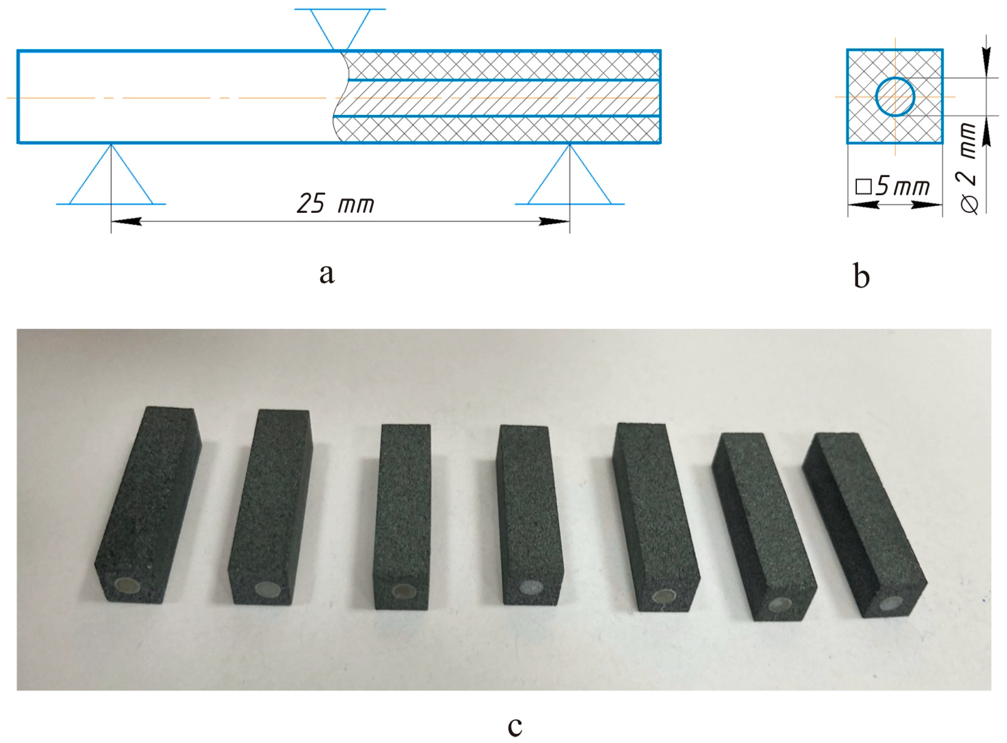
The flexural strength of the materials was evaluated at room and at elevated temperatures in a 3-point bending test using specimens 5 × 5 × 35 mm3 in size with a support span of 25 mm and a diameter of Mo wire of 2 mm (Figure 4). One batch of samples was tested at room temperature in air and the second batch at 1500 °C in an inert atmosphere (argon). The amount of residual silicon in the samples tested at 1500 °C and at 20 °C was the same, the samples had an identical composition. The mechanical tests were carried out on an electromechanical testing machine (universal testing machine I1147M, 50 kN, Tochpribor, Ivanovo, Russia) with a force sensor of 50 kN. High-temperature tests were carried out in a special chamber installed on the testing machine. An omega-shaped carbon–carbon heater was installed in the chamber, inside which a molybdenum alloy test fixture was placed on rods that moved freely through the chamber.
3. Results and Discussion
3.1. Phase Composition and Microstructure
A study of the microstructure of the obtained samples showed that a complex interfacial silicide layer with a predominant MoSi2 phase formed on the surface layer of the wire as a result of the chemical interaction of the silicon melt with the molybdenum. Figure 5 shows an image of the microstructure of the SiC–Si–C composite reinforced with metal wire as well as the results of the phase analysis. The average thickness of the silicide layer on all samples was about 100–150 µm. In this case, a stable bond of the interfacial layer with both the residual metal and the SiC-based ceramic matrix was observed. Figure 5c illustrates the structure of the silicide layer. The thin interlayer between the residual metal and the disilicide is the lower silicide Mo5Si3, which was confirmed by the results of the elemental analysis. The thickness of the complex layer, as well as its components, can vary depending on the time and temperature of the heat treatment [24]. A detailed study of the reaction kinetics and a prediction and analysis of the results would be worth a special mention in future works. The peaks of all these phases are visible in the XRD pattern (Figure 6)
Obviously, reinforcing elements with a diameter of less than 100–200 µm will completely transform into MoSi2. Due to the fact that MoSi2 tends to be plastically deformed above the viscoelastic transition temperature [25], it is possible to obtain a ceramic matrix reinforced with MoSi2 fibers with a quasi-plastic fracture pattern and, consequently, an increased crack resistance at elevated temperatures [26].
A substantial reduction in the amount of residual silicon in the ceramic matrix can be achieved by using finer fractions of carbon powder as well as additives of fine powder of refractory metals. In this case, the fine powder of a refractory metal would completely transform into silicide during the interaction with the silicon melt.
3.2. Mechanical Properties
Loading diagrams and a photo of the specimens after testing are shown in Figure 7. At the first stage of the loading process, failure specific to ceramic materials was observed. Tensile stress on the lower periphery of the section led to the destruction of the ceramic part and the rapid propagation of a crack upwards. However, the reinforcing element stopped the growth of the crack and, by plastic deformation, ensured the preservation of the bearing capacity of the sample. The matrix started to crack, and the load transferred from the matrix to the MoSi2–Mo5Si3 shell-like reaction zone interphase and molybdenum wire. Interfacial debonding and slipping occurred in the material and the wire became the main load-bearing component. Under the action of the externally applied load, the shell interphase ensured the efficient transfer of the load and provided a critical role in the strengthening of the Mo wire. As the load continued to increase, the wire began to pull out at the shell/matrix interface and broke under the maximum load. Figure 7e,f show a gap between the reacted shell and the unreacted core due to prominent necking of the unreacted Mo wire. The quasi-plastic nature of the fracture was observed at room temperature and at 1500 °C. Failure stress values for each series of tests are shown in Table 1. A significant reduction in the critical stress at 1500 °C was due to a large quantity of residual silicon in the ceramic matrix. The large difference in the strength characteristics at 20 and 1500 °C is partly due to the presence of free silicon in the bulk of the ceramic, which is in the molten state at 1500 °C. When silicon passes into the liquid phase with a decrease in volume, micro-voids are formed in the ceramics, which are stress concentrators.
3.3. Mechanism of Silicon Carbide Formation
An analysis of the mechanism of silicon carbide formation at the interface between the silicon melt and the carbon showed that the surface layer of SiC is formed quickly (in less than 1 min) [1]. Then, the SiC layer grows to a maximum thickness of about 10–15 μm within 10–15 min. After that, the growth of the SiC layer practically stops. Therefore, a longer siliconization process makes no practical sense. The slowing down and cessation of the growth of the SiC layer occur because a continuous layer of silicon carbide is formed at the entire silicon–carbon interface. This continuous SiC layer isolates the areas with residual free carbon from the liquid silicon and prevents further dissolution of the carbon. The subsequent growth of silicon carbide is very slow. It can proceed on the side of the silicon melt if the liquid silicon is supersaturated with carbon. The SiC layers slowly grow until the carbon concentration in the silicon melt decreases to an equilibrium level. The growth rate of the SiC layer and its final thickness are mainly affected by the choice of the grade of graphite (carbon material) used to prepare the powder.
The method makes it possible to vary the phase composition (i.e., the ratio of the SiC, C, and Si phases) and the structure of the ceramics depending on the requirements imposed by the operating conditions of the item type. By varying the ratio of graphite powder of different fractions, the amount of binder, and the molding pressure, after carbonizing the binder (in a protective atmosphere at 900 °C), porous graphite blanks with a density of 0.9–1.46 g/cm3 can be obtained. SiC-based ceramics with a density from 2.32 to 3.1 g/cm3 can be manufactured by the LSI of porous carbon blanks with a density of 1.46 and 0.9 g/cm3, respectively (Figure 8).
4. Conclusions
A method for producing SiC-based composites reinforced with Mo wire was developed. The composites were manufactured by infiltrating liquid silicon into porous carbon blanks with embedded metal wire.
A study of the microstructure of the obtained samples showed that a chemical reaction of the molten silicon with the molybdenum wire occurs. As a result, a complex interfacial silicide layer with a predominant MoSi2 phase is formed in the surface layer of the Mo wire. In addition, a thin layer of Mo5Si3 is formed between the residual metal and the disilicide. A stable bond of the interfacial layer with the residual metal and the SiC-based ceramic matrix was observed.
Mechanical tests on the obtained samples for three-point bending at 20 and 1500 °C showed quasi-plastic damage. The reinforcing elements act as stoppers for propagating cracks in the event of a matrix failure.
The developed method for producing composites with a ceramic matrix reinforced with metal wire makes it possible to reduce the cost of machining and manufacturing products with complex geometric shapes.
In the future, we plan to study the kinetics of the reaction of silicide formation on the surface of the reinforcing element, including the effects of exposure time and temperature on the thickness of the formed layer. In addition, evaluating the shear strength at the phase boundaries of silicide/metal and silicide/silicon carbide and creating a method for obtaining cermet (CM) with a wire of refractory metal (diameter less than 200 μm) are of interest. This would significantly improve the strength of the material.
Author Contributions
Conceptualization, S.S. and V.K.; methodology, A.K. and S.S.; formal analysis, A.K., K.K. and S.S.; writing—original draft preparation, V.K.; writing—review and editing, B.S. and K.K.; supervision, B.S. and V.K.; project administration, V.K.; funding acquisition, V.K. All authors have read and agreed to the published version of the manuscript.
Funding
This work was supported by the Ministry of Science and Higher Education of the Russian Federation, project no. FSFN-2023-0004.
Institutional Review Board Statement
Not applicable.
Informed Consent Statement
Not applicable.
Data Availability Statement
All data required to reproduce these experiments are present in the article.
Conflicts of Interest
The authors declare no conflict of interest.
References
- Bansal, N.P. (Ed.) Handbook of Ceramic Composites; Springer: New York, NY, USA, 2005; ISBN 978-1-4020-8133-0. [Google Scholar] [CrossRef]
- Yamada, K.; Mohri, M. Properties and Applications of Silicon Carbide Ceramics. In Silicon Carbide Ceramics—1; Sömiya, S., Inomata, Y., Eds.; Springer: Dordrecht, The Netherlands, 1991. [Google Scholar] [CrossRef]
- Herderick, E.D.; Cooper, K.; Ames, N. New approach to join SiC for accident-tolerant nuclear fuel cladding. Adv. Mater. Proc. 2012, 170, 24. [Google Scholar] [CrossRef]
- Heimann, R.B. Classic and Advanced Ceramics: From Fundamentals to Applications; Wiley-VCH Verlag GmbH & Co. KgaA: Weinheim, Germany, 2010; Volume 553, ISBN 978-3-527-32517-7. [Google Scholar] [CrossRef]
- Launey, M.E.; Ritchie, R.O. On the fracture toughness of advanced materials. Adv. Mater. 2009, 21, 2103–2110. [Google Scholar] [CrossRef]
- Kriegesmann, J.; Lipp, A.; Reinmuth, K.; Schwetz, K.A. Strength and Fracture Toughness of Silicon Carbide. In Ceramics for High-Performance Applications III; Lenoe, E.M., Katz, R.N., Burke, J.J., Eds.; Army Materials Technology Conference Series; Springer: Boston, MA, USA, 1983; Volume 1. [Google Scholar] [CrossRef]
- Miller, J.H.; Liaw, P.K. Fracture Toughness of Ceramics and Ceramic Matrix Composites. In ASM Handbook, Mechanical Testing and Evaluation; Kuhn, H., Medlin, D., Eds.; ASM International: Materials Park, OH, USA, 2000; Volume 8, p. 654. [Google Scholar] [CrossRef]
- Unlu, M.D.; Goller, G.; Yucel, O.; Sahin, F.C. The spark plasma sintering of silicon carbide ceramics using alumina. Acta Phys. Pol. A 2014, 125, 257. [Google Scholar] [CrossRef]
- Simonenko, E.P.; Gordeev, A.N.; Kolesnikov, A.F.; Lysenkov, A.S.; Nagornov, I.A.; Kurlov, V.N.; Ershov, A.E.; Sevast’yanov, V.G.; Kuznetsov, N.T. Behavior of ultra-high temperature ceramic material HfB2-SiC-Y3Al5O12 under the influence of supersonic dissociated air flow. Russ. J. Inorg. Chem. 2020, 65, 1596. [Google Scholar] [CrossRef]
- Xiang, L.; Cheng, L.; Shi, L.; Zhang, L. Laminated HfC–SiC Ceramics produced by aqueous tape casting and hot pressing. Ceram. Int. 2015, 41, 14406. [Google Scholar] [CrossRef]
- Simonenko, E.P.; Simonenko, N.P.; Kolesnikov, A.F.; Chaplygin, A.V.; Lysenkov, A.S.; Nagornov, I.A.; Mokrushin, A.S.; Kuznetsov, N.T. Investigation of the effect of supersonic flow of dissociated nitrogen on ZrB2-HfB2-SiC ceramics doped with 10 vol.% carbon nanotubes. Materials 2022, 15, 8507. [Google Scholar] [CrossRef]
- Zhou, L.; Zheng, Y.; Du, S.; Li, H. Fabrication of AlN-SiC-TiB2 Ceramics by self-propagating high temperature synthesis and hot isostatic pressing. Mater. Sci. Forum 2007, 546–549, 1505. [Google Scholar] [CrossRef]
- Ordoñez, S.; Carvajal, L.; Martínez, V.; Agurto, C.; Marín, J.; Olivares, L.; Iturriza, I. Fracture toughness of SiC-Cu based alloys cermets. Mater. Sci. Forum 2005, 498–499, 350. [Google Scholar] [CrossRef]
- Lim, C.B.; Yano, T.; Iseki, T. Microstructure and mechanical properties of RB-SiC/MoSi2 composites. J. Mater. Sci. 1989, 24, 4144. [Google Scholar] [CrossRef]
- Woetting, G.; Caspers, B.; Gugel, E.; Westerheide, R. High-temperature properties of SiC-Si3N4 particle composites. J. Eng. Gas Turb. Power 2000, 122, 8. [Google Scholar] [CrossRef]
- Tian, W.B.; Kan, Y.M.; Zhang, G.J.; Wang, P.L. Effect of carbon nanotubes on the properties of ZrB2–SiC ceramics. Mater. Sci. Eng. A 2008, 487, 568. [Google Scholar] [CrossRef]
- Naslain, R. Design, Preparation and properties of non-oxide CMCs for application in engines and nuclear reactors; an overview. Compos. Sci. Technol. 2004, 64, 155. [Google Scholar] [CrossRef]
- Christin, F. Design, Fabrication and application of thermostructural composites (TSC) like C/C, C/SiC and SiC/SiC composites. Adv. Eng. Mater. 2002, 4, 903. [Google Scholar] [CrossRef]
- Katoh, Y.L.; Snead, L.; Henager, C.H., Jr.; Nozawa, T.; Hinoki, T.; Iveković, A.; Novak, S.; Gonzalez de Vicente, S.M. Current status and recent research achievements in SiC/SiC composites. J. Nucl. Mater. 2014, 455, 387. [Google Scholar] [CrossRef]
- Mainzer, B.; Lin, C.; Frieß, M.; Riedel, R.; Riesch, J.; Feichtmayer, A.; Fuhr, M.; Almanstötter, J.; Koch, D. Novel ceramic matrix composites with tungsten and molybdenum fiber reinforcement. J. Eur. Ceram. Soc. 2021, 41, 3030. [Google Scholar] [CrossRef] [Green Version]
- An, Q.; Chen, J.; Ming, W.; Chen, M. Machining of SiC ceramic matrix composites: A review. Chin. J. Aeronaut. 2021, 34, 540. [Google Scholar] [CrossRef]
- Shikunov, S.L.; Kurlov, V.N. SiC-based composite materials obtained by siliconizing carbon matrices. Tech. Phys. 2017, 62, 1869. [Google Scholar] [CrossRef]
- Ershov, A.E.; Shikunov, S.L.; Kurlov, V.N. Method of calculating the phase composition of SiC-Si-C materials obtained by silicon infiltration of carbon matrices. Tech. Phys. 2017, 62, 903. [Google Scholar] [CrossRef]
- Kochmańska, A.E.; Jarlaczyńska, A.; Baranowska, J. Formation of silicide and silicide-aluminide coatings on molybdenum alloy during slurry cementation process: Influence of slurry volume. Materials 2021, 14, 6940. [Google Scholar] [CrossRef] [PubMed]
- Aikin, R.M. On the ductile-to brittle transition temperature in MoSi2. Scr. Metall. Mater. 1992, 26, 1025. [Google Scholar] [CrossRef]
- Petrovic, J.J.; Vasudevan, A.K. Key developments in high temperature structural silicides. Mater. Sci. Eng. A 1999, 261, 1–5. [Google Scholar] [CrossRef]
Figure 1.
Stages of obtaining products based on SiC ceramics by liquid silicon infiltration (LSI) of porous carbon blanks.
Figure 1.
Stages of obtaining products based on SiC ceramics by liquid silicon infiltration (LSI) of porous carbon blanks.

Figure 2.
Scheme for obtaining blanks reinforced with molybdenum wire.

Figure 3.
Scheme of the LSI process for porous carbon blanks with embedded Mo wire: (a) silicon impregnation process and (b) resulting composite structure.
Figure 3.
Scheme of the LSI process for porous carbon blanks with embedded Mo wire: (a) silicon impregnation process and (b) resulting composite structure.

Figure 4.
(a) Three-point bending scheme; (b) configuration of the cross-section of samples; and (c) photograph of specimens for mechanical testing.
Figure 4.
(a) Three-point bending scheme; (b) configuration of the cross-section of samples; and (c) photograph of specimens for mechanical testing.

Figure 5.
(a,b) Microstructure of SiC-based ceramic with Mo wire; (c) phase analysis of the metal–silicide interface.
Figure 5.
(a,b) Microstructure of SiC-based ceramic with Mo wire; (c) phase analysis of the metal–silicide interface.

Figure 6.
XRD pattern of the SiC-based ceramic with Mo wire. The Mo peaks are marked by the vertical red lines. All other phases are marked by symbols explained in the inset.
Figure 6.
XRD pattern of the SiC-based ceramic with Mo wire. The Mo peaks are marked by the vertical red lines. All other phases are marked by symbols explained in the inset.

Figure 7.
Loading diagrams: (a) sample 1–2 at room temperature and (b) sample 2–2 at 1500 °C. Photographs of samples after testing: (c) sample 1–2 at room temperature and (d) sample 2–2 at 1500 °C. (e,f) Micrographs of failure surfaces of sample 1–2 after testing.
Figure 7.
Loading diagrams: (a) sample 1–2 at room temperature and (b) sample 2–2 at 1500 °C. Photographs of samples after testing: (c) sample 1–2 at room temperature and (d) sample 2–2 at 1500 °C. (e,f) Micrographs of failure surfaces of sample 1–2 after testing.

Figure 8.
Microstructure of SiC-based ceramics with various phase compositions SiC/C/Si: (a) 91/1/8 %wt. (carbon blank density is 0.9 g/cm3), (b) 70/25/5, (c) 40/50/10, and (d) 25/70/5 (carbon blank density is 1.46 g/cm3).
Figure 8.
Microstructure of SiC-based ceramics with various phase compositions SiC/C/Si: (a) 91/1/8 %wt. (carbon blank density is 0.9 g/cm3), (b) 70/25/5, (c) 40/50/10, and (d) 25/70/5 (carbon blank density is 1.46 g/cm3).


Table 1.
Mechanical test data.
| Test Temperature (°C) | Sample Number | Failure Stress Value (MPa) |
|---|---|---|
| 20 | 1–1 | 323.39 |
| 1–2 | 364.62 | |
| 1–3 | 386.17 | |
| 1–4 | 419.78 | |
| Average value | 373.49 | |
| 1500 | 2–1 | 112.71 |
| 2–2 | 114.74 | |
| 2–3 | 82.64 | |
| Average value | 103.36 |
Disclaimer/Publisher’s Note: The statements, opinions and data contained in all publications are solely those of the individual author(s) and contributor(s) and not of MDPI and/or the editor(s). MDPI and/or the editor(s) disclaim responsibility for any injury to people or property resulting from any ideas, methods, instructions or products referred to in the content. |
© 2023 by the authors. Licensee MDPI, Basel, Switzerland. This article is an open access article distributed under the terms and conditions of the Creative Commons Attribution (CC BY) license (https://creativecommons.org/licenses/by/4.0/).
Share and Cite
MDPI and ACS Style
Kaledin, A.; Shikunov, S.; Komarov, K.; Straumal, B.; Kurlov, V. SiC-Based Composite Material Reinforced with Molybdenum Wire. Metals 2023, 13, 313. https://doi.org/10.3390/met13020313
AMA Style
Kaledin A, Shikunov S, Komarov K, Straumal B, Kurlov V. SiC-Based Composite Material Reinforced with Molybdenum Wire. Metals. 2023; 13(2):313. https://doi.org/10.3390/met13020313
Chicago/Turabian StyleKaledin, Alexei, Sergey Shikunov, Kirill Komarov, Boris Straumal, and Vladimir Kurlov. 2023. "SiC-Based Composite Material Reinforced with Molybdenum Wire" Metals 13, no. 2: 313. https://doi.org/10.3390/met13020313
Note that from the first issue of 2016, this journal uses article numbers instead of page numbers. See further details here.