
Cutting Chatter in Ultrasonic Elliptical Vibration Cutting and Its Influence on Surface Roughness and Tool Wear

State Key Laboratory of High-Performance Precision Manufacturing, Dalian University of Technology, Dalian 116024, China
*
Author to whom correspondence should be addressed.
Metals 2023, 13(6), 1078; https://doi.org/10.3390/met13061078
Submission received: 10 March 2023
/
Revised: 3 April 2023
/
Accepted: 4 April 2023
/
Published: 7 June 2023
(This article belongs to the Special Issue High Performance Machining of Difficult-to-Process Metals)
Abstract
:Ultrasonic elliptical vibration cutting has a wide range of applications in the field of precision cutting of difficult-to-machine metal materials. However, due to its intermittent cutting characteristics and the weak rigidity of the horn, cutting chatter is prone to occur during its cutting process, which has an important impact on cutting surface quality and tool wear. In this paper, the rigid/viscoplastic rod model is used to simulate the horn in the ultrasonic elliptical vibration cutting device, and the influence factors of the amplitude-frequency response of the horn are analyzed. The influence of cutting speed and cutting depth on cutting chatter was studied by ultrasonic elliptical vibration cutting experiment of tungsten heavy alloy, and the influence of cutting chatter on cutting surface morphology and diamond tool wear was studied. The research shows that cutting speed will change the excitation frequency of the horn, and reasonable cutting speed can inhibit the occurrence of cutting chatter and avoid resonance of the horn. The cutting depth will affect the excitation amplitude and amplify the vibration amplitude when chatter or resonance occurs. The experimental results show that in ultrasonic elliptical vibration cutting of heavy tungsten alloy, chatter suppression can significantly improve the quality of the cutting surface and reduce the wear of diamond tools.
1. Introduction
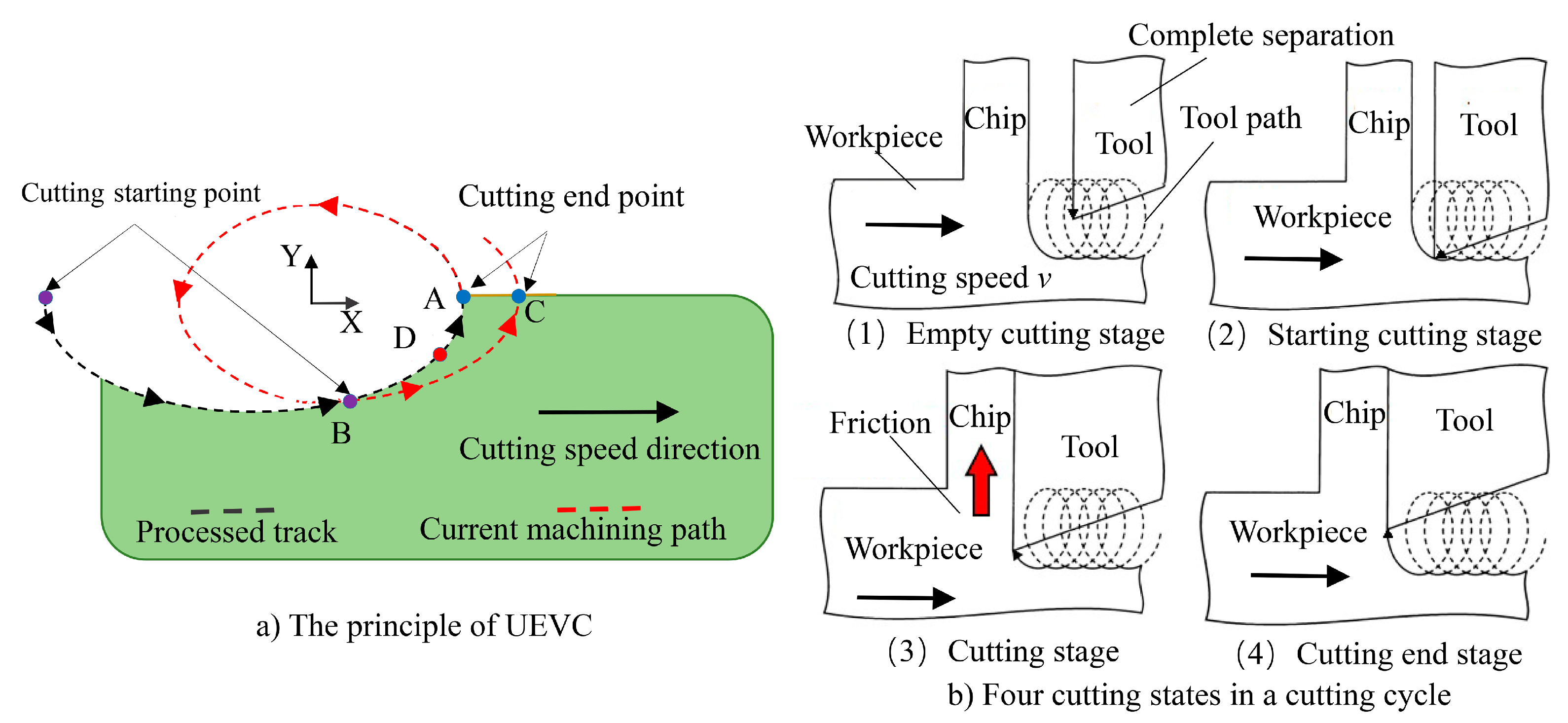
Ultrasonic elliptical vibration cutting (UEVC) was introduced by Shamoto and Moriwaki in CIRP on 1994 [1]. Its working principle is that piezoelectric ceramics drive the horn to vibrate at high frequencies, which in turn causes the tool to move in a circular or elliptical trajectory to achieve material removal [2,3]. The working principle of UEVC is different from that of conventional turning (CT) and ultrasonic assisted turning (UAT). In each vibration-cutting cycle, the tool and the material will have a complete separation process. At the same time, the size and direction of the friction force on the rake face of the tool will constantly change, and the actual cutting angle of the tool will also change [4,5]. Compared with UEVC, UAT can only separate tool and material in one direction. There is always a face in the flank or rake face that is in contact with the workpiece material at all times, which makes the separation incomplete. There are also great differences between UAT and UEVC in terms of actual cutting angle, cutting trajectory and acceleration in cutting [6,7].
Intermittent cutting is one of the characteristics of UEVC. In each vibration cycle, the complete separation of tool and material is conducive to the entry of cutting fluid into the cutting zone, achieving better heat dissipation and lubrication, thereby reducing tool wear and improving cutting surface quality [8,9,10]. The diamond tool can also be applied to the cutting of ferrous metals [11,12], and improve the machinability of hard and brittle materials [13,14]. However, intermittent cutting can also lead to periodic changes in cutting force, resulting in the chatter of horn and tool in UEVC device. As we all know, cutting chatter in precision/ultra-precision machining is to be avoided, which will not only reduce the cutting surface quality but also seriously affect the tool life [15,16,17].
To suppress chatter in cutting, domestic and foreign scholars have also carried out related research. Urbikain et al. [18] studied the chatter problem when turning parts with interruption characteristics. A stability model of intermittent turning chatter is proposed when the main vibration is perpendicular to the chip cross-section. This method must calculate the dynamic displacement factor depending on the tool’s vibration frequency. Studies have shown that cutting speed and tool cutting cycle are the key factors affecting vibration. Wang et al. [19] studied the chatter problem in the machining of lean tools such as boring and milling, analyzed the working principles of two different tuned mass dampers, and explained the advantages of tuned mass dampers according to the simulation and modeling results. The influence of the stiffness and damping parameters of the components in the tuned mass damper on the suppression of chatter was analyzed. Feng et al. [20,21] monitored and counted the cutting chatter in milling, and analyzed the influence of cutting chatter on surface roughness. According to the established chatter model, the optimization of machining parameter selection is realized. Ahmed et al. [6] compared the cutting force of ultrasonic-assisted turning and traditional turning, and studied the influence of vibration frequency, amplitude, and feed rate on cutting force. The results show that the cutting force of ultrasonic-assisted cutting can be reduced by 30% compared with traditional turning, but the fluctuation range of cutting force is larger than that of traditional turning. Kamada et al. [22] studied the composite chatter based on low-frequency and high-frequency vibration in the cutting process, and analyzed the influence of phase difference and vibration frequency on chatter. The cutting experimental results show that setting a reasonable phase difference can effectively suppress cutting chatter. Etxebarria et al. [23] developed an inertial actuator that compensates for the cutting force through reverse motion control during cutting, thereby suppressing chatter. From the above research, it can be found that the existing methods of flutter suppression can be divided into two ways: increasing flutter damping and optimizing machining parameters [24,25,26,27].
UEVC involves many processing parameters. This paper mainly studies the flutter suppression method from the perspective of parameter matching. By establishing the rigid/viscoplastic rod model of the UEVC device, the influencing factors of cutting chatter are analyzed, and the processing parameters are optimized. Through the UEVC experiment of tungsten heavy alloy, the influence of cutting chatter on surface roughness and tool wear was studied.
2. Vibration Model of Horn and Its Influencing Factors Analysis
UEVC can be decomposed into sinusoidal motion in X/Y directions. The trajectory equation of the tool relative to the workpiece is shown in Formula (1), as shown in Figure 1a. Each UEVC cycle, according to the fluctuation of cutting force, can be divided into four stages, namely, the empty cutting stage, starting cutting stage, cutting stage, and cutting end stage, as shown in Figure 1b [5]. In the empty cutting stage, the cutting force is zero. In the initial cutting stage, the tool begins to contact the material, and the cutting force increases with the increase of the cutting amount.
where A and B are amplitude in x and y directions, f is vibration frequency, φ is phase difference, v is cutting speed.
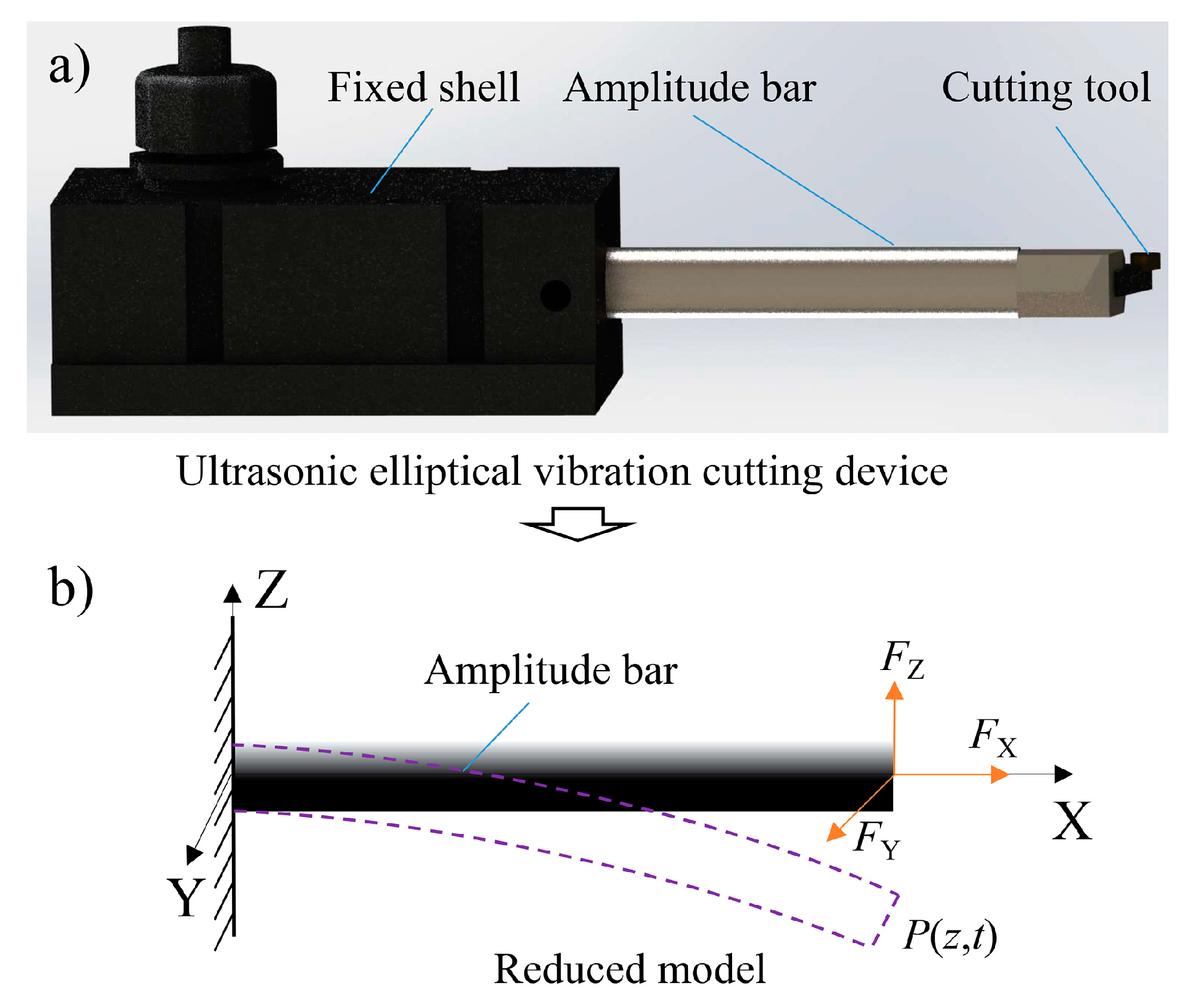
The UEVC device, as shown in Figure 2a, can be divided into two parts: horn and fixed shell. The force situation in the cutting process can be simplified into a model as shown in Figure 2b, and a coordinate system (X, Y, Z) is established, where the Z-axis is the symmetry axis of the cross-section of the horn, the Y-axis is the neutral axis of the cross-section of the horn, and the X-axis coincides with the axis of the horn.
In the cutting process, the horn will be affected by the X/Y/Z three directions of force, respectively, FX, FY, FZ, the cutting force FX along the axial direction of the horn, the cutting force FY along the cutting feed direction, the cutting force FZ is along the cutting speed direction. The cutting force FX will compress the horn, and the fluctuation of the force will cause the change of the cutting state in the cutting depth direction. However, under ultrasonic elliptical vibration cutting, the cutting force is small, and the horn is rigid, so it will not have a significant impact on the cutting surface morphology. The cutting force FY will make the ridge at the feed junction no longer uniform, which will have a significant impact on the cutting surface morphology in the feed direction, but the impact on the cutting surface pits is very tiny, so it is not the focus of this study. The cutting force FZ is the same as the ultrasonic vibration direction, which will lead to the low frequency vibration of the horn. It can also be seen from the cutting surface pits that the reason is mainly caused by the low frequency of the horn along the cutting direction. Based on the above analysis, cutting force FX and cutting force FY are not the main causes of cutting chatter, so they are ignored in this study. This paper focuses on the problem of tool chatter caused by cutting force FZ.
The motion equation of the horn particle is:
The damping vibration term is:
Into the Formula (1) can be obtained:
By comparing the coefficients of and can be obtained:
where x is the displacement, H is the force amplitude, and is the frequency of the forced force, is the natural frequency, m is the mass of the horn, the length of the horn is l, the cross-section is S, and the density is , one end is fixed and the other end is free to move. It is subjected to the combined action of transverse harmonic load FZ, elastic force k, viscous resistance and periodic forcing force .
It can be seen from the formula that the amplitude of the horn is a function of the periodic forcing force and the vibration frequency. When the natural frequency of the horn is the same as the frequency of the periodic forcing force, the displacement amplitude A will have a maximum value, that is, resonance occurs.
When , the phase difference between the displacement and the forced force is:
The resonance displacement is:
The resonance velocity is:
It can be seen from Formulas (7)–(11) that when the excitation frequency is the same as the natural frequency of the horn or its integer times, the horn will resonate, and the vibration amplitude is the largest. The excitation frequency is affected by cutting speed, ultrasonic frequency, the amplitude ratio of the long axis to the short axis, and so on, in which the cutting speed and ultrasonic frequency, and amplitude ratio of the long axis to a short axis with each other. Therefore, as long as the natural frequency of the UEVC device is obtained, the excitation frequency in the cutting process can be adjusted by changing the cutting speed.
3. Experiment Scheme of UEVC
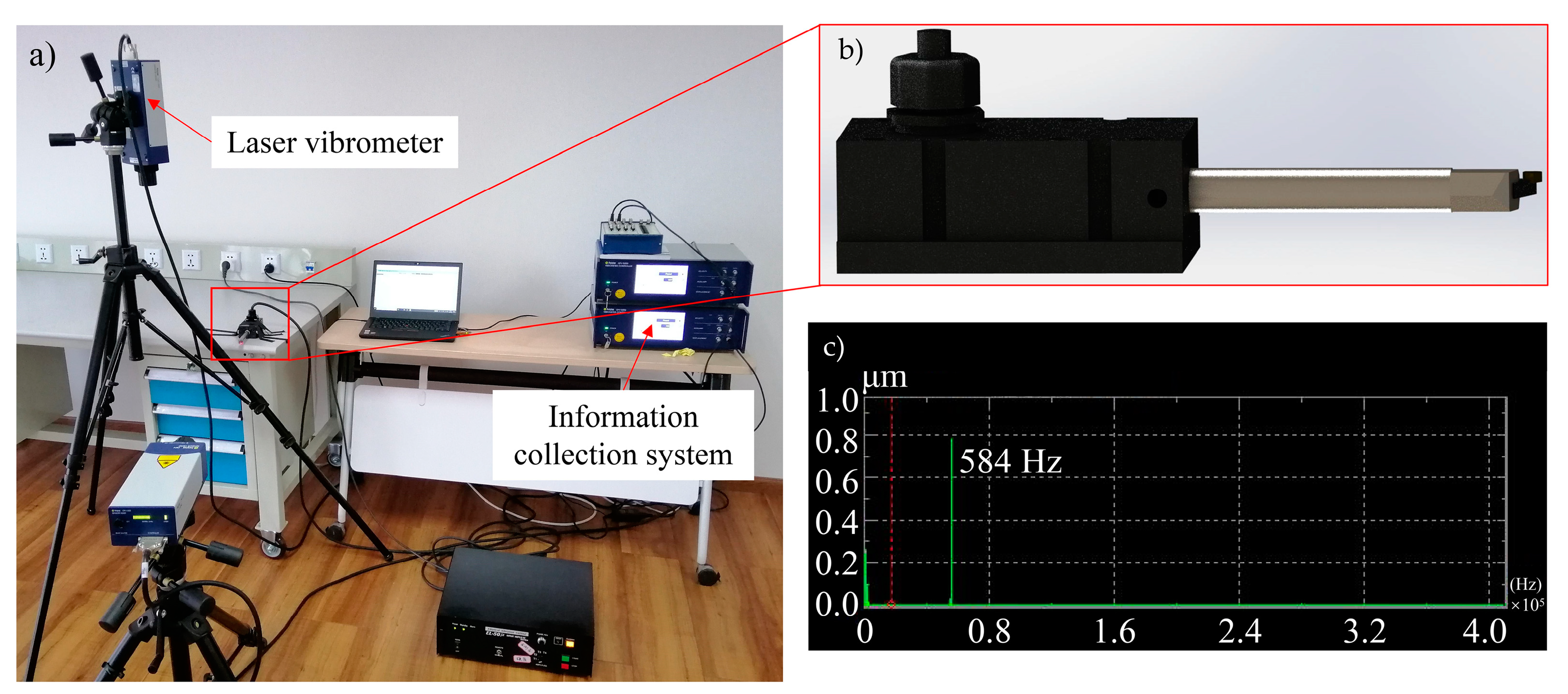
To suppress cutting chatter, the natural frequency of the UEVC device must be obtained first. The UEVC device used in the experiment was manufactured by Toga Corporation in Tokyo, Japan. The model is EL-50jz/LA, the ultrasonic vibration frequency is 34 kHz, and the amplitude P-P is 4 μm. The natural frequency of the horn of the ultrasonic elliptical vibration device is detected by a laser vibrometer (Polytec Inc., Karlsruhe, Baden-Württemberg, Germany). The measured natural frequency of the ultrasonic elliptical vibration horn is 584 Hz, as shown in Figure 3.
Based on the above analysis, when the excitation frequency is 584 Hz, or an integer multiple of it, resonance occurs in the UEVC process, and the amplitude is the largest. To study the influence of cutting chatter on cutting quality and tool wear, it is necessary to set different machining parameters to form different cutting chatter. The ultrasonic amplitude is P-P 4 μm, the ultrasonic frequency is 34 kHz, the long and short axis ratio is 1, the feed rate is 20 μm/r, the single crystal diamond tool arc radius is R1mm, the tool back angle is 15°, and the tool front angle is 0°. According to Formula (8), when the cutting speed is 1 m/min and 2.2 m/min, the excitation frequency is an integer multiple of 584 Hz, which is 34,456 Hz and 50,244 Hz, respectively. When the cutting speed is 1.5 m/min, the excitation frequency is 34,164 Hz and the resonant displacement is the smallest. Therefore, when studying the chatter of UEVC, three sets of experiments (serial number: 1, 2, 3) were set up. The cutting speeds were 1 m/min, 1.5 m/min, 2.2 m/min, and the cutting depth was 4 μm. This experiment mainly studies the influence of cutting chatter on cutting surface roughness. In order to further study the effect of cutting depth on cutting chatter, another two sets of experiments (serial number: 4, 5) were set up. When the cutting speed was 1 m/min, the cutting depth was 8 μm. When the cutting speed is 1.5 m/min, the cutting depth is 8 μm. As shown in Table 1.
To study the effect of chatter on tool wear in UEVC, two sets of machining parameters with different chatter conditions were selected to carry out UEVC experiments. In the two groups of experiments, the feed rate is 20 μm/r, the ultrasonic frequency is 34 kHz, the ultrasonic amplitude is P-P 4 μm, the tool is a single crystal diamond tool, the front angle is 0°, the back angle is 15°, the cutting arc radius is 1 mm, and the amplitude ratio is 1. By changing the cutting speed, different cutting chatter conditions are generated under two experimental conditions, as shown in Table 2. The total cutting length is 600 m, and each interval is 50 m. The tool wear is detected, and the wear of the rake face and the retreat of the flank face are measured respectively to obtain the specific tool wear.
4. UEVC Experimental Device
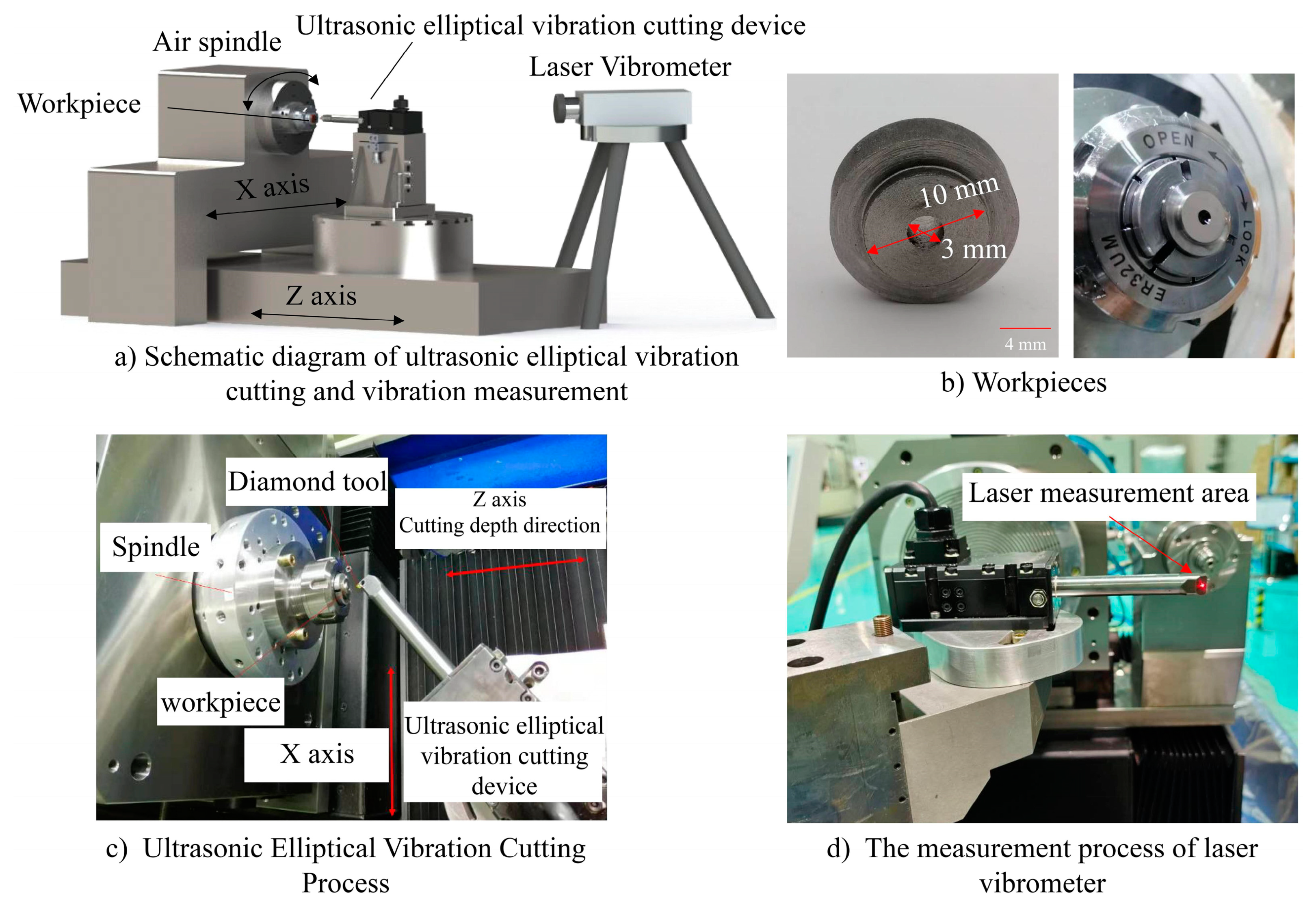
To study the cutting chatter phenomenon in the UEVC process and the influence of cutting chatter on cutting surface morphology and tool wear, the UEVC experiment was carried out. The experimental material is a tungsten heavy alloy, in which the W element content is 94.5–95.5%, the Ni content is 3.2–3.4%, and the Fe content is 1.4–1.6%. The main properties of tungsten heavy alloy materials are shown in Table 3.
The lathe used in the experiment is a three-axis diamond lathe developed by the Institute of Mechanical Manufacturing Technology, China Academy of Engineering Physics, Chengdu, China. The machine model is UPl-9200, mainly including C/spindle, X-axis and Z-axis. The X-axis stroke is 300 mm, the Z-axis stroke is 350 mm, the processing aperture is 200 mm, the positioning accuracy is 1 μm, and the repeated positioning accuracy is 0.5 μm. The diameter of the test piece is 10 mm, the thickness is 6 mm, and there is a hole with a diameter of 3 mm in the middle of the test piece. Cutting chatter is detected by a laser vibrometer during the cutting process. The measurement distance of the laser vibrometer is 0.5–100 m, the measurement frequency range is DC-24 MHz, the best speed resolution is 0.02 μm/s, and the best displacement resolution is 0.15 nm. Its model is the DASP V11 multi-channel signal acquisition system, developed by the China Oriental Institute of Noise and Vibration (DASP-V11, Orient Smart Testing Technology Co.,Ltd, Beijing, China). The main equipment and placement position used in the cutting experiment are shown in Figure 4.
5. Experimental Results Detection and Analysis
5.1. Effect of Cutting Chatter on Surface Morphology
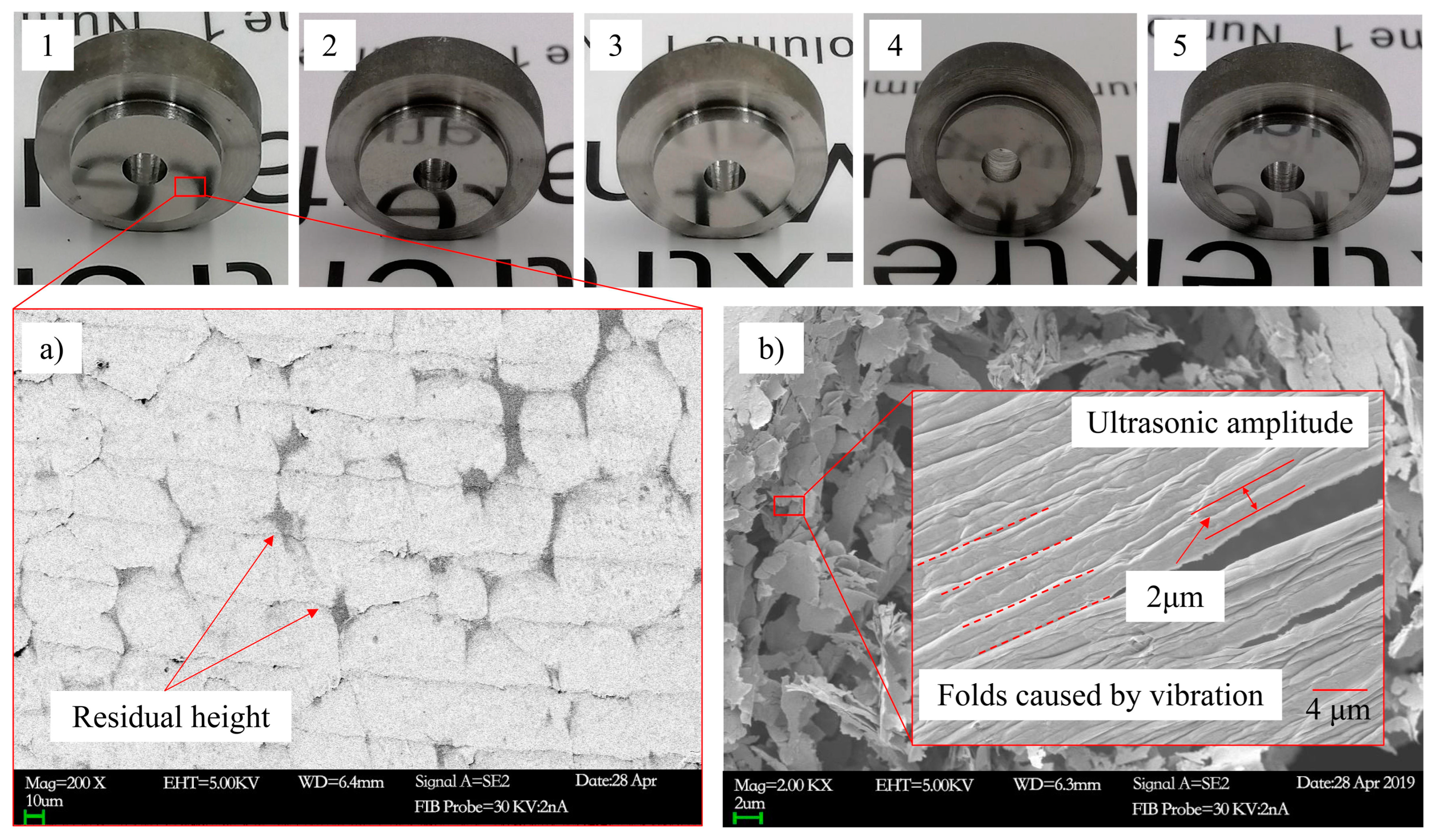
The cutting samples under different cutting conditions are shown in Figure 5. The sample number corresponds to the processing parameters of Table 1. Figure 5a is the Scanning Electron Microscope (SEM) surface of sample 1. It can be seen from the figure that the cutting residual height is generated by the feed rate. In the direction of cutting speed, the morphological changes caused by the horn chatter cannot be seen under the scanning electron microscope. Figure 5b is the tungsten alloy chip under this cutting condition. It is easier to see the influence of ultrasonic vibration on the processing of the chip. Ultrasonic vibration will cause the chip to wrinkle, which is mainly due to the UEVC characteristics. The continuous contact and separation of the tool and the material will also change the cutting force, which is also one of the main causes of cutting chatter.
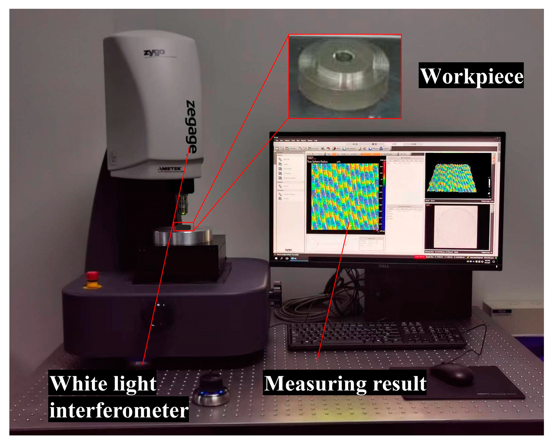
The cutting surface morphology detection equipment is a white light interferometer, which is produced by ZYGO company in Middlefield, CT, USA, and the model is zegage. A 10-fold lens and confocal mode were used in the detection. The surface roughness testing standard follows the Chinese ISO 25178 standard. The detection site of tungsten heavy alloy cutting surface morphology is shown in Figure 6.
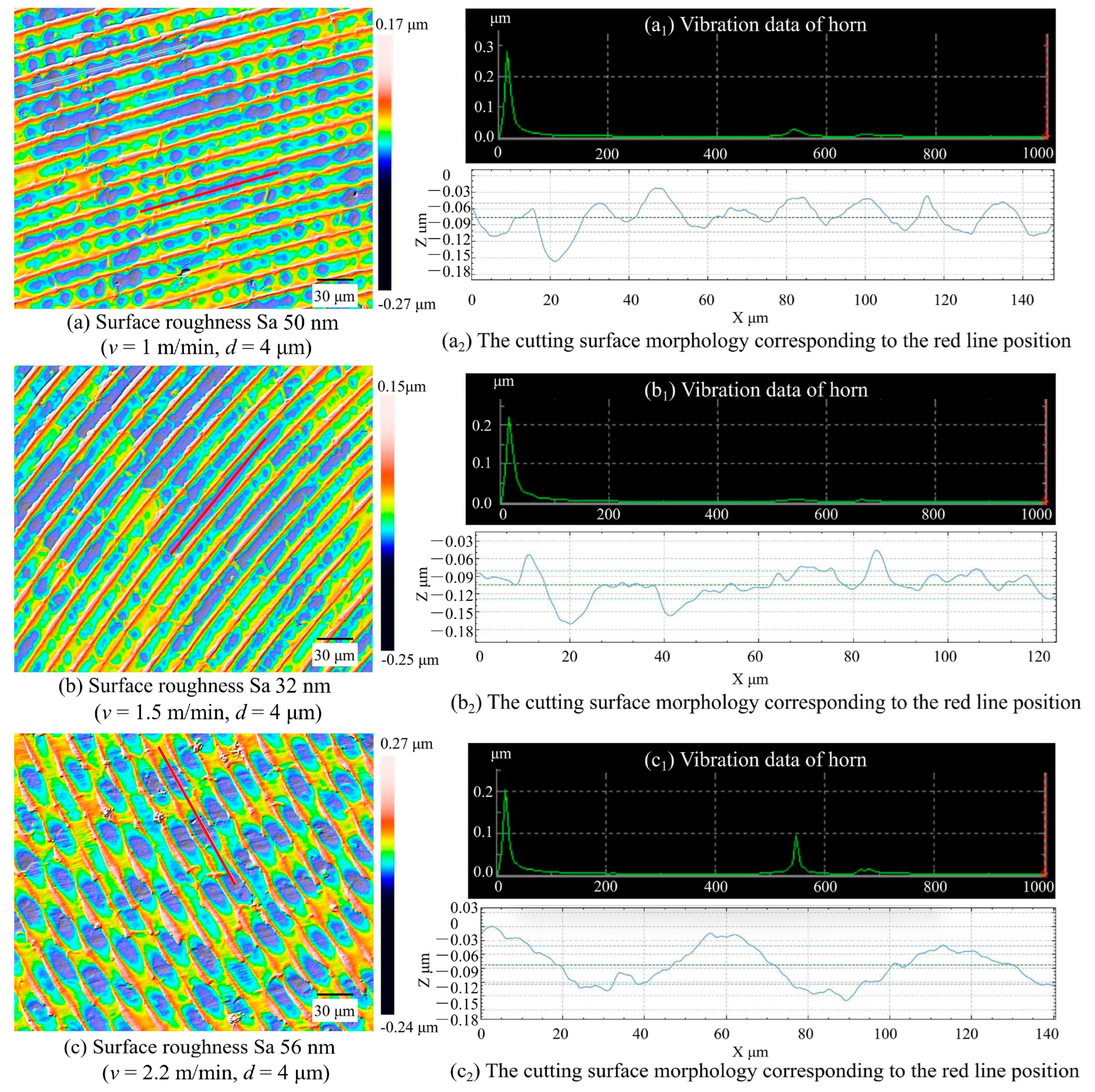
Figure 7 is the test results of cutting surface morphology of high specific gravity tungsten alloy. It can be seen from the figure that there are great differences in the cutting surface morphology of tungsten alloy samples at different cutting speeds. When the cutting speed is 1 m/min, since the excitation vibration is an integer multiple of the natural frequency of the horn of the UEVC device, the cutting excitation vibration and the horn vibration resonate at this time. At this time, a regular vibration pit is formed on the cutting surface. The depth of the vibration pit is about 0.07 μm, and the surface roughness Sa is 50 nm. When the cutting speed is 1.5 m/min, the resonance displacement is the smallest, and the vibration amplitude of the corresponding horn becomes smaller. Therefore, although vibration occurs during the cutting process, regular vibration pits will not be formed on the cutting surface. The cutting depth caused by vibration is about 0.03 μm, and the surface roughness Sa is 32 nm. When the cutting speed is 2.2 m/min, due to the cutting resonance, a uniform crater is formed. The depth of the crater is about 0.08 μm and the surface roughness Sa is 56 nm.
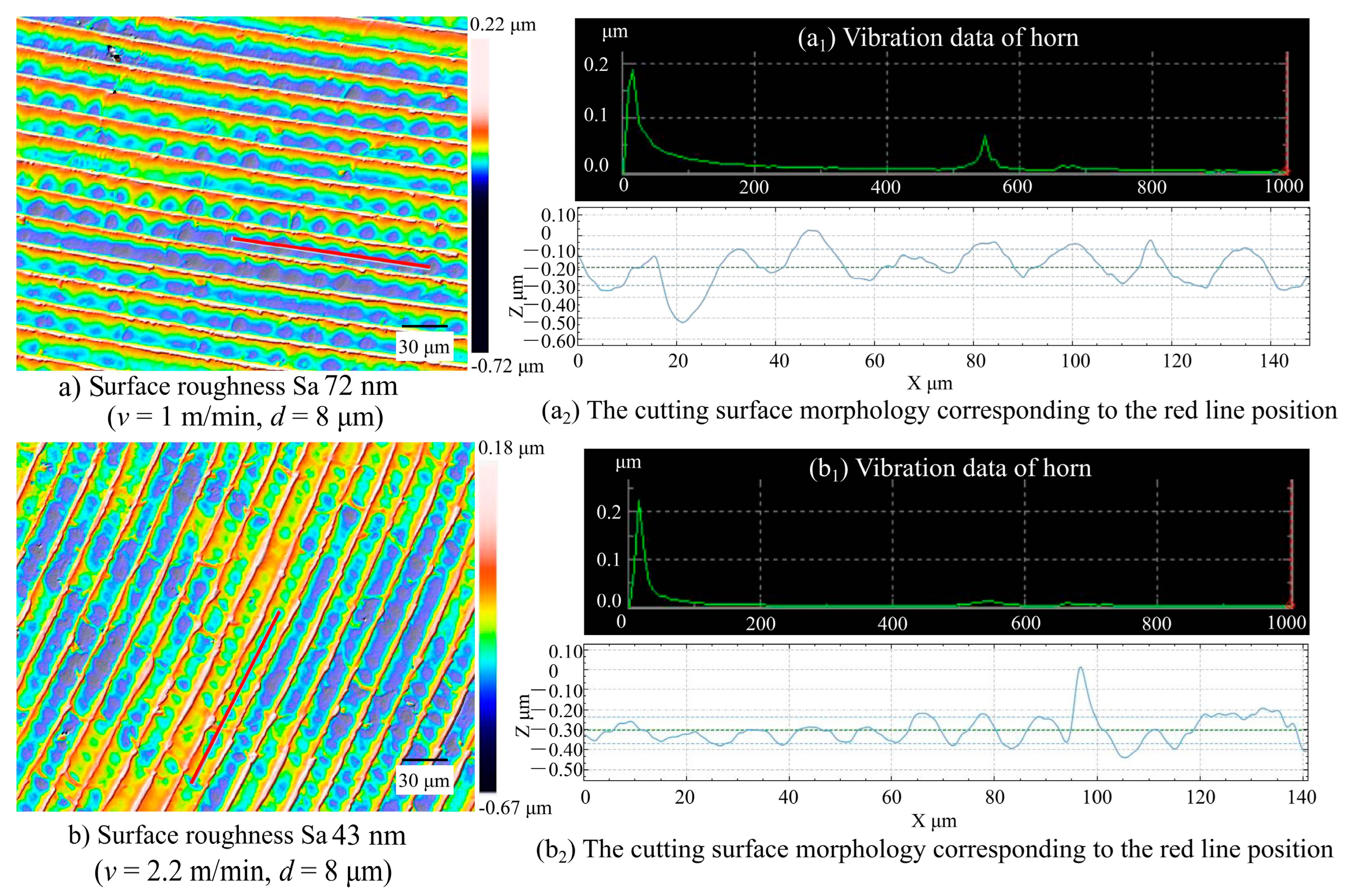
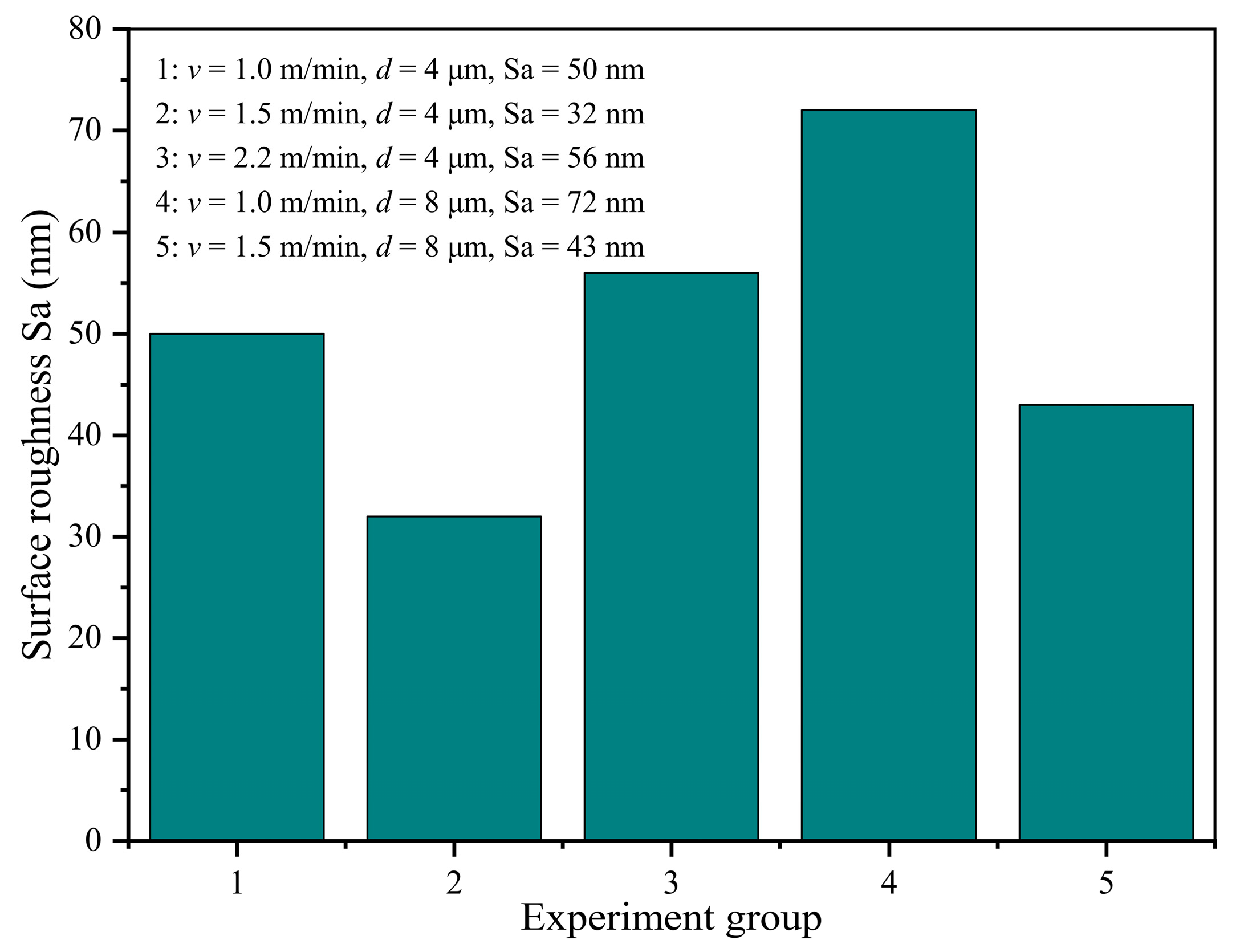
The cutting surface morphology under different cutting depths is shown in Figure 8. As can be seen from the figure, the change in cutting depth will not change the excitation frequency, so the change in cutting depth will have an impact on the vibration amplitude value, affecting the crater depth and cutting surface morphology. When the cutting speed is 1 m/min and the cutting depth is 8μm, obvious resonance occurs. The depth of the vibration pit is about 0.3 μm and the surface roughness Sa is 72 nm. When the cutting speed is 1.5 m/min and the cutting depth is 8 μm, the chatter amplitude is small, the crater depth is about 0.2 μm and the surface roughness Sa is 43 nm.
In the process of UEVC of tungsten heavy alloy, cutting chatter is difficult to avoid due to the existence of excitation frequency. However, the above experimental results show that by changing the cutting speed, the excitation frequency can be adjusted to suppress the cutting chatter. The cutting surface roughness under different cutting conditions is shown in Figure 9. It can be seen from the diagram that under the same cutting depth, due to the different cutting speeds, when the excitation frequency becomes an integer multiple of the natural frequency of the UEVC device, the cutting surface roughness is worse due to the cutting chatter. Under the same cutting speed, the change of cutting depth will not affect the excitation frequency, but it will affect the vibration amplitude and the surface roughness.
5.2. Effect of Cutting Chatter on Tool Wear
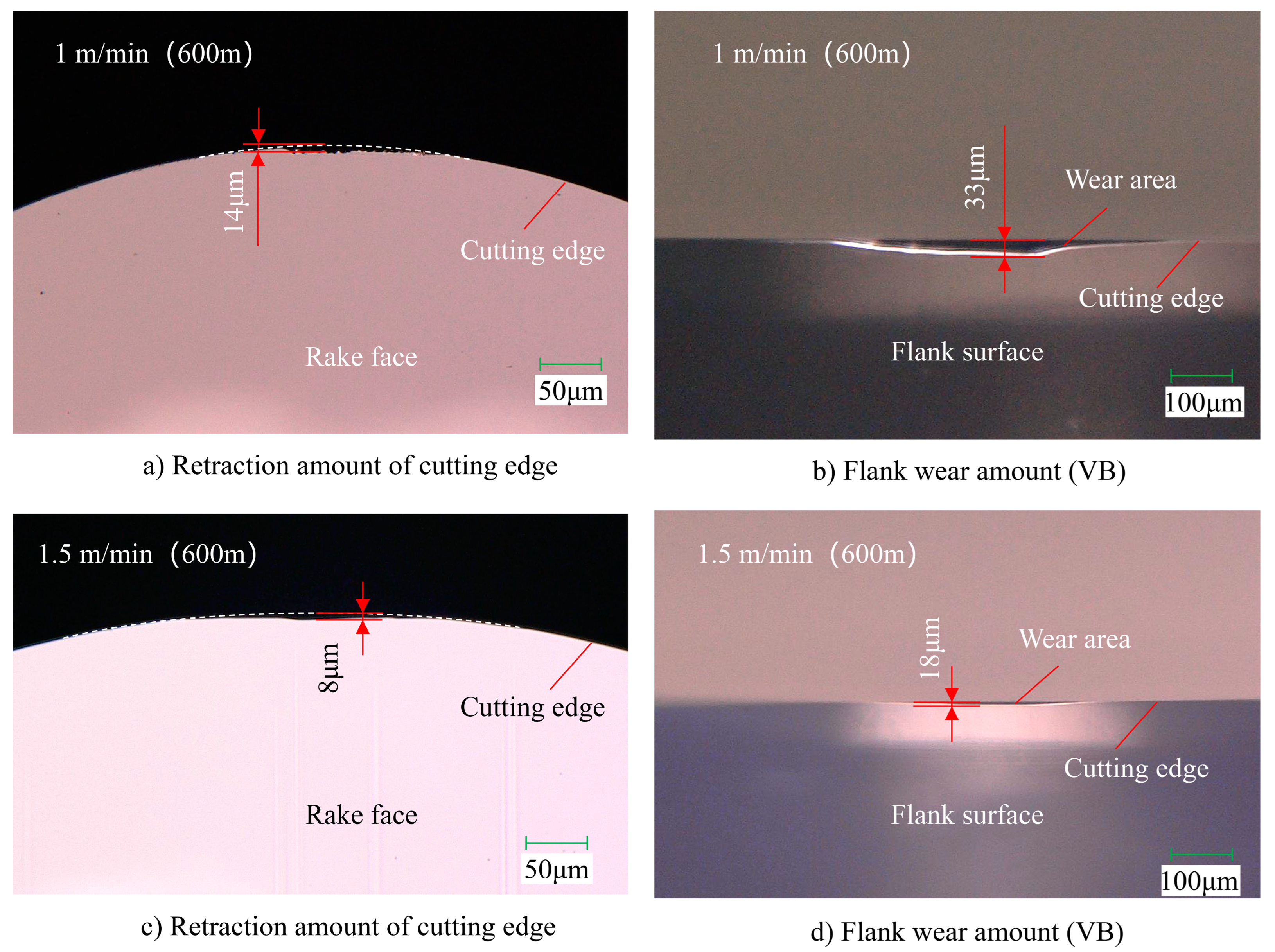
The wear of single crystal diamond tools at two cutting speeds is shown in Figure 10. Due to the different cutting chatter under the two cutting conditions, the influence of chatter on tool wear can be analyzed. As can be seen from the figure, when the cutting speed is 1 m/min, under UEVC diamond tool cutting edge retreat amount of 14 μm (Figure 10a), flank wear of 32.5 μm (Figure 10b). When the cutting speed is 1.5 m/min, the cutting edge retreat of the diamond tool is 8 μm (Figure 10c), and the flank wear is 18 μm (Figure 10d).
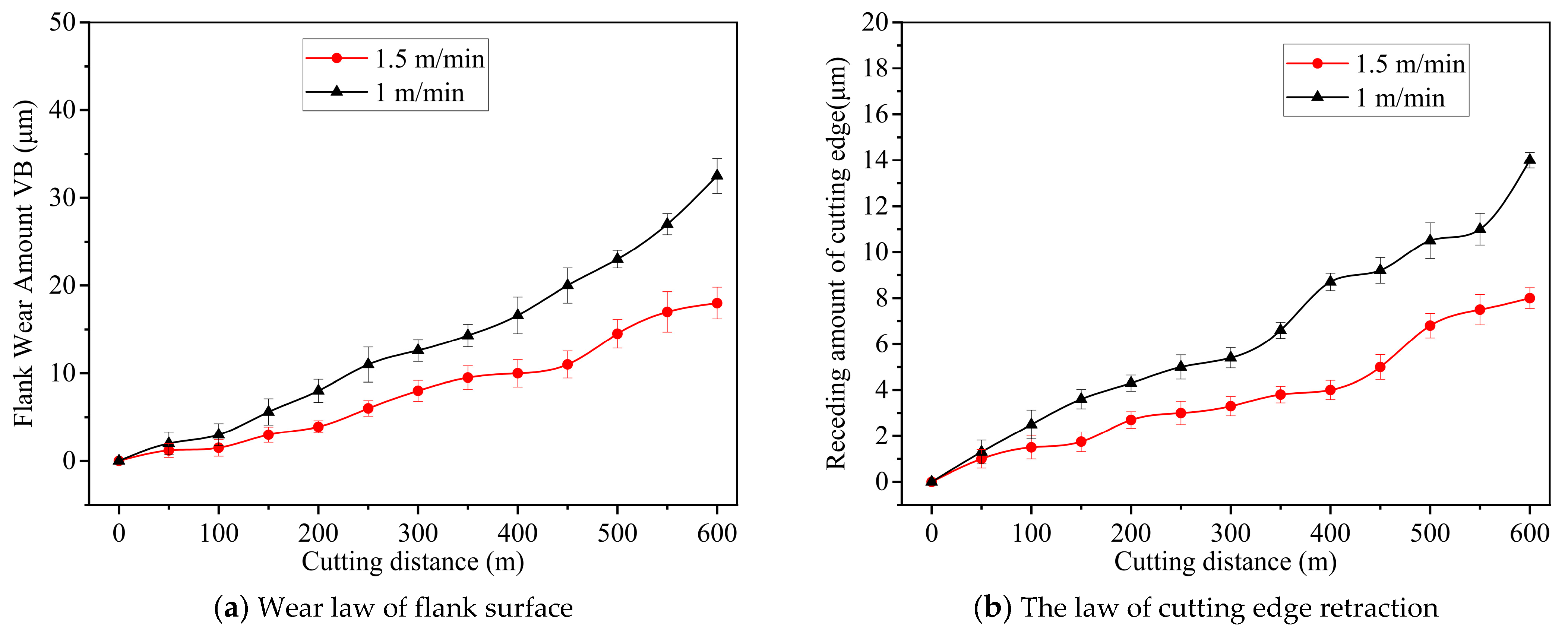
The wear of diamond tools was measured at intervals of 50 m, and the wear of diamond tools with different cutting distances was obtained, as shown in Figure 10. According to the principle of ultrasonic elliptical vibration cutting, the influence of cutting speed on tool wear is highly small within the maximum cutting speed. Therefore, it can be considered that the difference in the degree of tool wear in the figure is mainly caused by the cutting chatter. The experimental results in Figure 6 show that the cutting chatter is severe when the cutting speed is 1 m/min; when the cutting speed is 1.5 m/min, the cutting chatter is low. It can be seen that with the increase in cutting distance, tool flank wear is also increasing. At the same cutting distance, a chatter will increase the wear degree of the tool flank. When the cutting distance is 600 m, the tool with cutting chatter has a flank wear of 32 μm. The flank wear of the tool with smaller chatter is 18 μm, and the flank wear is reduced by about 45%, as shown in Figure 11a. When the cutting distance is 600 m, the tool with cutting chatter has a cutting edge retreat of 14 μm. The tool with smaller cutting chatter has a cutting edge retreat of 8 μm, and the cutting edge retreat is reduced by about 43%, as shown in Figure 11).
6. Conclusions
The horn in the ultrasonic elliptical vibration cutting device needs to vibrate under the drive of piezoelectric ceramics, so its rigidity cannot be very large, so it is very likely to produce chatter under the action of external force. And ultrasonic elliptical vibration cutting itself is a kind of intermittent cutting; therefore, the cutting force is periodic change. In this paper, the influence factors of cutting chatter are analyzed by establishing the rigid/viscoplastic rod model of horn. The influence of cutting chatter on surface roughness and tool wear was studied by using tungsten heavy alloy as experimental material. The following conclusions are obtained.
- (1)
- According to the rigid/viscoplastic rod model of horn, cutting chatter is affected by cutting speed, ultrasonic frequency, ultrasonic amplitude and other factors, and cutting speed and ultrasonic frequency influence each other. When the excitation frequency is the same as the natural frequency of the horn or its integer times, the horn will resonate, and the flutter is the most severe. The cutting chatter will form more regular pits on the cutting surface, and the pit frequency is the same as the natural frequency of the ultrasonic elliptical vibration cutting device.
- (2)
- In ultrasonic elliptical vibration cutting, by changing the cutting speed, the cutting excitation frequency in the cutting process can be changed, so that it is far away from the natural frequency of the ultrasonic elliptical vibration cutting device, thereby suppressing the cutting chatter and improving the cutting surface quality. When the cutting speed is 1 m/min, 1.5 m/min, 2.2 m/min, the cutting surface roughness Sa is 50 nm, 32 nm and 56 nm.
- (3)
- Since the cutting depth does not change the excitation frequency, it is not the cutting parameter that affects the chatter. However, increasing the cutting depth, the pits will deepen on the basis of the original cutting chatter. Under the same processing parameters, the cutting depth increases from 4 μm to 8 μm, and the surface roughness Sa changes from 50 nm to 72 nm.
- (4)
- In ultrasonic elliptical vibration cutting, inhibiting cutting chatter can significantly reduce diamond tool wear, and with the increase of cutting distance, the effect of inhibiting tool wear is more obvious. The experimental results show that when the cutting distance is 600 m, the flank wear of the single crystal diamond tool is reduced by about 45% and the rake face retreat is reduced by about 40%.
Author Contributions
Conceptualization, Y.P. and R.K.; methodology, G.L.; software, G.L.; validation, J.L. and S.Y.; formal analysis, G.L.; investigation, J.L. and Y.B.; resources, Y.B. and Z.D.; data curation, Y.P., S.Y. and Z.D.; writing—original draft preparation, Y.P.; writing—review and editing, G.L. and R.K.; visualization, J.L.; supervision, Y.P., S.Y. and R.K.; project administration, Z.D.; funding acquisition, Y.B. and R.K. All authors have read and agreed to the published version of the manuscript.
Funding
This work was supported by the National Key Research and Development Program of China [grant number: 2022YFB3402300], National Natural Science Foundation of China [grant number: 52275411], Fundamental Research Funds for the Central Universities [grant number: DUT22ZD201] and High Level Talents Innovation Plan of Dalian [grant number: 2020RD02].
Data Availability Statement
The data presented in this study are available in the article.
Conflicts of Interest
On behalf of all authors, the corresponding author states that there is no conflict of interest.
References
- Shamoto, E.; Moriwaki, T. Study on Elliptical Vibration Cutting. CIRP Ann. 1994, 43, 35–38. [Google Scholar] [CrossRef]
- Moriwaki, T.; Shamoto, E. Ultrasonic Elliptical Vibration Cutting. CIRP Ann. 1995, 44, 31–34. [Google Scholar] [CrossRef]
- Shamoto, E.; Suzuki, N. Ultrasonic Vibration Diamond Cutting and Ultrasonic Elliptical Vibration Cutting. Compr. Mater. Process. 2014, 11, 405–454. [Google Scholar] [CrossRef]
- Zhang, J.; Cui, T.; Ge, C.; Sui, Y.; Yang, H. Review of micro/nano machining by utilizing elliptical vibration cutting. Int. J. Mach. Tools Manuf. 2016, 106, 109–126. [Google Scholar] [CrossRef]
- Brehl, D.E.; Dow, T.A. Review of vibration-assisted machining. Precis. Eng. 2008, 32, 153–172. [Google Scholar] [CrossRef]
- Ahmed, N.; Mitrofanov, A.; Babitsky, V.; Silberschmidt, V. Analysis of forces in ultrasonically assisted turning. J. Sound Vib. 2007, 308, 845–854. [Google Scholar] [CrossRef]
- Babitsky, V.I.; Mitrofanov, A.V.; Silberschmidt, V.V. Ultrasonically assisted turning of aviation materials: Simulations and experimental study. Ultrasonics 2004, 42, 81–86. [Google Scholar] [CrossRef]
- Maeng, S.; Ito, H.; Kakinuma, Y.; Min, S. Study on Cutting Force and Tool Wear in Machining of Die Materials with Textured PCD Tools Under Ultrasonic Elliptical Vibration. Int. J. Precis. Eng. Manuf. Technol. 2022, 10, 35–44. [Google Scholar] [CrossRef]
- Airao, J.; Nirala, C.K. Finite Element Modeling and Experimental Validation of Tool Wear in Hot-Ultrasonic-Assisted Turning of Nimonic 90. J. Vib. Eng. Technol. 2022, 1–19. [Google Scholar] [CrossRef]
- Bai, J.; Xu, Z.; Qian, L. Precision-improving manufacturing produces ordered ultra-fine grained surface layer of tungsten heavy alloy through ultrasonic elliptical vibration cutting. Mater. Des. 2022, 220, 110859. [Google Scholar] [CrossRef]
- Pan, Y.; Kang, R.; Dong, Z.; Du, W.; Yin, S.; Bao, Y. On-line prediction of ultrasonic elliptical vibration cutting surface roughness of tungsten heavy alloy based on deep learning. J. Intell. Manuf. 2022, 33, 675–685. [Google Scholar] [CrossRef]
- Usman, M.M.; Zou, P.; Yang, Z.; Lin, T.; Muhammad, I. Evaluation of micro-textured tool performance in ultrasonic elliptical vibration-assisted turning of 304 stainless steel. Int. J. Adv. Manuf. Technol. 2022, 121, 4403–4418. [Google Scholar] [CrossRef]
- Nath, C.; Rahman, M.; Neo, K. A study on ultrasonic elliptical vibration cutting of tungsten carbide. J. Mater. Process. Technol. 2009, 209, 4459–4464. [Google Scholar] [CrossRef]
- Pan, Y.; Bai, J.; Xu, Z. Theoretical and numerical studies of surface microstructural transformation in ultrasonic elliptical vibration cutting tungsten heavy alloys. Int. J. Adv. Manuf. Technol. 2022, 123, 3943–3953. [Google Scholar] [CrossRef]
- Kayhan, M.; Budak, E. An experimental investigation of chatter effects on tool life. Proc. Inst. Mech. Eng. B J. Eng. Manuf. 2009, 223, 1455–1463. [Google Scholar] [CrossRef] [Green Version]
- Ambhore, N.; Kamble, D.; Chinchanikar, S. Evaluation of Cutting Tool Vibration and Surface Roughness in Hard Turning of AISI 52100 Steel: An Experimental and ANN Approach. J. Vib. Eng. Technol. 2020, 8, 455–462. [Google Scholar] [CrossRef]
- Sahu, G.N.; Deora, P.; Law, M.; Wahi, P. Adaptive Model-Free Gain Tuning for Active Damping of Machine Tool Vibrations. J. Vib. Eng. Technol. 2022, 10, 2799–2808. [Google Scholar] [CrossRef]
- Urbikain, G.; López de Lacalle, L.; Fernández, A. Regenerative vibration avoidance due to tool tangential dynamics in interrupted turning operations. J. Sound Vib. 2014, 333, 3996–4006. [Google Scholar] [CrossRef]
- Wang, M.; Qin, P.; Zan, T.; Gao, X.; Han, B.; Zhang, Y. Improving optimal chatter control of slender cutting tool through more accurate tuned mass damper modeling. J. Sound Vib. 2021, 513, 116393. [Google Scholar] [CrossRef]
- Ye, J.; Feng, P.; Xu, C.; Ma, Y.; Huang, S. A novel approach for chatter online monitoring using coefficient of variation in machining process. Int. J. Adv. Manuf. Technol. 2018, 96, 287–297. [Google Scholar] [CrossRef]
- Xu, C.; Feng, P.; Zhang, J.; Yu, D.; Wu, Z. Milling stability prediction for flexible workpiece using dynamics of coupled machining system. Int. J. Adv. Manuf. Technol. 2016, 90, 3217–3227. [Google Scholar] [CrossRef]
- Kamada, Y.; Kitakaze, A.; Sannomiya, K.; Nakaya, T.; Sasahara, H. Mechanism to suppress regenerative chatter vibration due to the effect of air-cutting and multiple regeneration during low frequency vibration cutting. Precis. Eng. 2022, 78, 1–18. [Google Scholar] [CrossRef]
- Etxebarria, A.; Barcena, R.; Mancisidor, I. Active Control of Regenerative Chatter in Turning by Compensating the Variable Cutting Force. IEEE Access 2020, 8, 224006–224019. [Google Scholar] [CrossRef]
- Hayasaka, T.; Nam, S.; Jung, H.; Shamoto, E.; Saito, K. Proposal of ‘accelerative cutting’ for suppression of regenerative chatter. CIRP Ann. 2018, 67, 401–404. [Google Scholar] [CrossRef]
- Mohammadi, Y.; Ahmadi, K. Finite-amplitude stability in regenerative chatter: The effect of process damping nonlinearity and intermittent cutting in turning. J. Sound Vib. 2022, 537, 117158. [Google Scholar] [CrossRef]
- Yan, B.; Zhu, L. Research on milling stability of thin-walled parts based on improved multi-frequency solution. Int. J. Adv. Manuf. Technol. 2019, 102, 431–441. [Google Scholar] [CrossRef]
- Mishra, R.; Singh, B. Extenuating Chatter Vibration in Milling Process Using a New Ensemble Approach. J. Vib. Eng. Technol. 2022, 10, 1235–1252. [Google Scholar] [CrossRef]
Figure 1.
UEVC principle and cutting process.

Figure 2.
(a) The UEVC device, and (b) Its horn force model.

Figure 3.
(a) The natural frequency detection of UEVC device, (b) Ultrasonic elliptical vibration cutting device, and (c) Frequency domain.
Figure 3.
(a) The natural frequency detection of UEVC device, (b) Ultrasonic elliptical vibration cutting device, and (c) Frequency domain.

Figure 4.
The process of UEVC and laser vibration measurement.

Figure 5.
Tungsten alloy cutting surface under different cutting conditions. (a) The cutting samples under different cutting conditions: (1) v = 1 m/min, d = 4 μm, (2) v = 1.5 m/min, d = 4 μm, (3) v = 2.2 m/min, d = 4 μm, (4) v = 1 m/min, d = 8 μm, (5) v = 1.5 m/min, d = 8 μm, and (b) The tungsten alloy chip under the cutting condition of v = 1 m/min, d = 4 μm.

Figure 6.
Tungsten heavy alloy cutting surface topography detection site.

Figure 7.
Cutting surface morphology at different cutting speeds.

Figure 8.
Cutting surface morphology under different cutting depths.

Figure 9.
Cutting surface roughness under different cutting conditions.

Figure 10.
Diamond tool wear at different cutting speeds.

Figure 11.
Diamond tool wear law under different cutting distances.


Table 1.
UEVC experimental parameters.
| Serial Number | Cutting Speed (v) | Cutting Depth (d) |
|---|---|---|
| 1 | 1 m/min | 4 μm |
| 2 | 1.5 m/min | 4 μm |
| 3 | 2.2 m/min | 4 μm |
| 4 | 1 m/min | 8 μm |
| 5 | 1.5 m/min | 8 μm |
Table 2.
Experimental scheme of diamond tool wear.
| Serial Number | Cutting Speed | Cutting Depth | Cutting Distance |
|---|---|---|---|
| 1 | 1 m/min | 4 μm | 600 m |
| 2 | 1.5 m/min | 4 μm | 600 m |
Table 3.
Tungsten heavy alloy material performance parameters.
| Name | Tungsten Heavy Alloy (95W) |
|---|---|
| Material component | 95%W, 3%Ni, 2%Fe |
| Heat treatment | Sintering |
| Density (g/cm3) | 18.10 ± 0.15 |
| Elongation (%) | 8–22 |
| Tensile strength (MPa) | 800–1100 |
| Hardness (HRC) | 27–32 |
| Density (g/cm3) | 17.2−17.9 |
Disclaimer/Publisher’s Note: The statements, opinions and data contained in all publications are solely those of the individual author(s) and contributor(s) and not of MDPI and/or the editor(s). MDPI and/or the editor(s) disclaim responsibility for any injury to people or property resulting from any ideas, methods, instructions or products referred to in the content. |
© 2023 by the authors. Licensee MDPI, Basel, Switzerland. This article is an open access article distributed under the terms and conditions of the Creative Commons Attribution (CC BY) license (https://creativecommons.org/licenses/by/4.0/).
Share and Cite
MDPI and ACS Style
Li, G.; Liu, J.; Pan, Y.; Bao, Y.; Yin, S.; Dong, Z.; Kang, R. Cutting Chatter in Ultrasonic Elliptical Vibration Cutting and Its Influence on Surface Roughness and Tool Wear. Metals 2023, 13, 1078. https://doi.org/10.3390/met13061078
AMA Style
Li G, Liu J, Pan Y, Bao Y, Yin S, Dong Z, Kang R. Cutting Chatter in Ultrasonic Elliptical Vibration Cutting and Its Influence on Surface Roughness and Tool Wear. Metals. 2023; 13(6):1078. https://doi.org/10.3390/met13061078
Chicago/Turabian StyleLi, Gan, Jinbo Liu, Yanan Pan, Yan Bao, Sen Yin, Zhigang Dong, and Renke Kang. 2023. "Cutting Chatter in Ultrasonic Elliptical Vibration Cutting and Its Influence on Surface Roughness and Tool Wear" Metals 13, no. 6: 1078. https://doi.org/10.3390/met13061078
Note that from the first issue of 2016, this journal uses article numbers instead of page numbers. See further details here.