A Comparative Study of Corrosion Behavior of Hard Anodized and Micro-Arc Oxidation Coatings on 7050 Aluminum Alloy


1
College of Materials Science and Engineering, Nanjing Tech University, Nanjing 210009, China
2
Instituto de Ciencia de Materiales de Aragón, CSIC-Universidad de Zaragoza, 50009 Zaragoza, Spain
3
Xiamen Advanced Materials Academy, Luoyang Ship Material Research Institute, Xiamen 361006, China
*
Author to whom correspondence should be addressed.
Metals 2018, 8(3), 165; https://doi.org/10.3390/met8030165
Submission received: 19 January 2018
/
Revised: 23 February 2018
/
Accepted: 7 March 2018
/
Published: 8 March 2018
Abstract
:Two kinds of metal oxide coatings were fabricated on 7050 Al alloy by hard anodization (HA) and micro-arc oxidation (MAO) techniques. The microstructure, phase composition, and corrosion behavior of the two coatings were studied by scanning electron microscopy, X-ray diffraction, and corrosion tests, respectively. When compared with the HA coating, the MAO one was more effective to isolate the substrate from the corrosive environment. In addition, as confirmed by electrochemical tests, the MAO coating was of better corrosion resistance than the HA coating. Furthermore, it was revealed by neutral salt spray test that the MAO coating could protect substrate alloy over 1140 h, while the HA coating can only protect substrate alloy for 46 h due to the amorphous composition and through thickness defects (micro-pores and micro-cracks).
1. Introduction
Due to their superior properties of good formability, lightweight, and high strength/weight ratio, aluminum alloys have a wide usage in the aerospace industry, especially in commercial transport aircraft and military fighter aircraft [1]. However, different kinds of local corrosions, such as pitting corrosion [2], intergranular corrosion [3], exfoliation corrosion [4], and stress corrosion [5], easily occur on aluminum alloys. All of these decrease the material strength and the plasticity substantially, and, thus, greatly limit the application of these materials. Hence, it is in urgent need of appropriate surface treatments to improve their corrosion resistance.
In the past half century, hard anodization (HA) as a cost effective solution has been widely used to enhance the corrosion resistance of aluminum alloys by forming an amorphous and porous coating with a thickness over 25 μm [6,7,8]. Nevertheless, it is not an environmentally friendly and economical technique, since it adopts an electrolyte with high concentrations of acid, high current density, and low temperature [9,10].
Along with the fast growth of the aerospace industry, the service environment of airframe materials becomes more severe. Therefore, it is necessary to develop a more environmental and effective anti-corrosion technologies to replace HA. Recently, micro-arc oxidation (MAO), as a novel surface treatment technique for Al, Mg, Ti, and their alloys [11,12,13], is attracting more interest in fabricating ceramic coatings to enhance the corrosion resistance, the wear resistance and the adhesion between the substrate and coating. There are fundamental differences between MAO and HA with respect to the nature of electrolyte, the voltage ranges, and the coating formation mechanism [14]. The corrosion resistance of MAO coating has been studied by a large number of studies and the results reveal that the MAO technique can improve the anti-corrosion properties of the substrate [15,16,17,18,19,20].
The MAO technique has been generally portrayed as a superior alternative to hard anodization, however, in recent studies, the corrosion resistance of MAO coating was mostly compared with substrate alloy [15,16], sealed MAO coating, [17,18], and MAO coating with additives [19,20]. Few studies investigated the difference in corrosion performance between MAO and HA coatings. Hence, the present study attempts to systematically compare the corrosion resistance of the two kinds of coating by potentiodynamic polarization tests and electrochemical impedance spectroscopy (EIS). Further, neutral salt spray testing was carried out to study the long-term corrosion behavior of HA and MAO coatings.
2. Materials and Methods
7050 Al alloy was used as an anode material, whose composition is Zn 6.2 wt %, Mg 2.10 wt %, Cu 2.40 wt %, Zr 0.12 wt %, Fe 0.15 wt %, Si 0.12 wt %, and Al balance. The samples (100 mm × 50 mm × 2 mm) were ultrasonically cleaned in pure ethanol and washed in distilled water eventually. The experimental conditions of MAO and HA are the most generic parameter and are summarized in Table 1. Different oxidation times of MAO and HA processes were selected so as to obtain the same coating thickness. The thickness of the coatings was measured by an eddy current thickness measurement instrument (FMP20, Fischer, Berlin, Germany).
The surface morphologies of coatings were imaged by field emission scanning electron microscopy (FE-SEM, JSM-6700F, JEOL, Tokyo, Japan) and the cross-section morphologies were imaged by scanning electron microscope (SEM, JSM-6510, JEOL, Tokyo, Japan). The phase composition of the MAO and HA treated samples were identified by X-ray diffraction (XRD, DMAX-RB, Rigaku, Tokyo, Japan, Cu Kα) at a potential of 45 kV and current of 200 mA. The scans were acquired from 10 to 90° (in 2θ) at a rate of 10°/min, with a grazing angle of 5°.
Potentiodynamic polarization testing and electrochemical impedance spectroscopy (EIS) were carried out with an electrochemical workstation (Autolab PGSTAT302N, Metrohm, Luzern, Switzerland) to compare the corrosion resistance of the HA- and MAO-treated samples at room temperature. A typical three-electrode cell system, a platinum plate as the auxiliary electrode, Ag/AgCl (saturated with KCl) as the reference electrode, and the sample as the working electrode (0.5 cm2 exposed area) was employed in the tests. After the sample as immersed in 3.5 wt % NaCl solution for 0.5 h, EIS was carried out with a signal amplitude of 10 mV over the open circuit potential in a frequency range of 100 kHz to 0.01 Hz. After 1 h immersion, the potentiodynamic polarization test was conducted at a rate of 1 mV/s. Neutral salt spray test (NSST) with 5 ± 0.1 wt % NaCl solution at 35 ± 2 °C as per GJB 150.11A-2009 for a duration of 1500 h was performed to evaluate the long-term corrosion behavior of the samples.
3. Results and Discussion
3.1. Microstructure
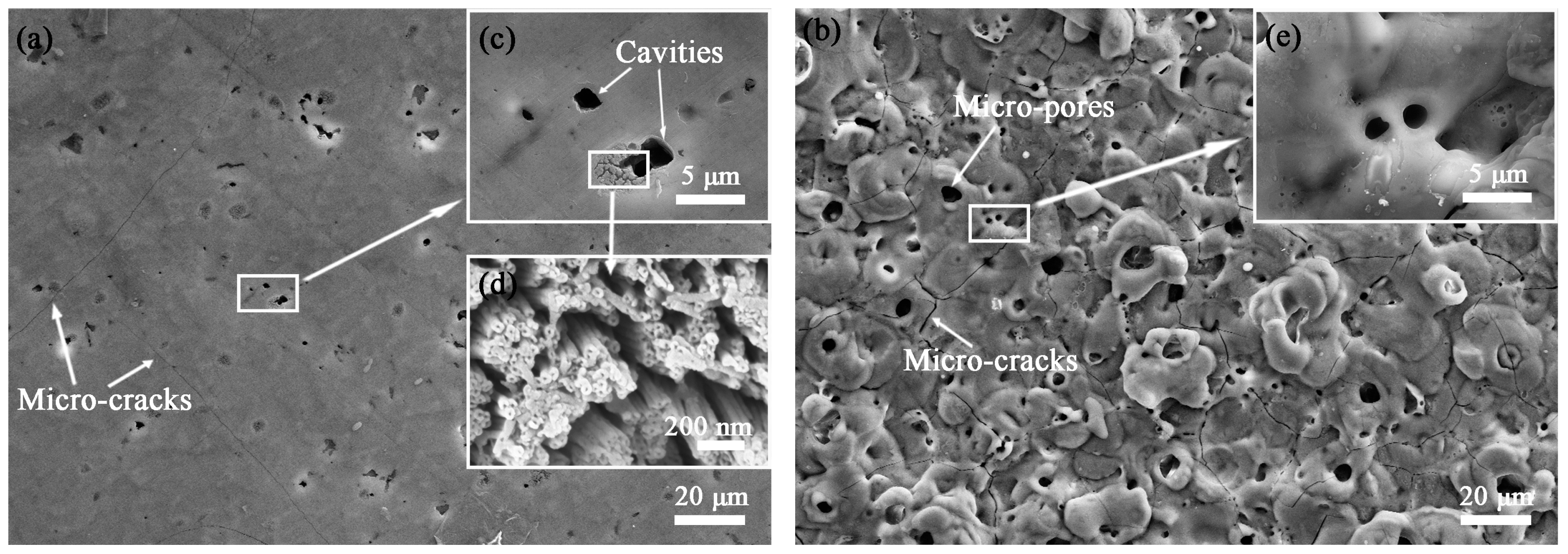
Figure 1 shows the surface morphology of HA and MAO coatings. There are some cavities of approximately 5–10 µm on the surface of the HA coating (Figure 1a), which was caused by the preferential dissolution of coarse intermetallic compounds into the electrolyte during anodizing [21]. Around the cavities, owing to the different dissolution rate of the substrate and the intermetallic compounds, stress concentration was easily formed and was released in the form of micro-cracks. The micro-cracks on the surface were straight, long (over 1000 µm), and perpendicular in Figure 1a. Due to the stress, cylindrical oxide cells with micro-pores (21–26 nm) spreading vertically down through the thickness of the coating were observed in Figure 1d [22,23,24]. When the cylindrical oxide cells adjoined to each other, they formed a porous layer.
The surface microstructure of the MAO coating (Figure 1b) was “crater-like” and was quite different from the HA coating. The micro-pores (1–10 μm), which were larger than that on the HA coating, were caused by the molten oxide jetting out from discharge channels under the high pressure of gas. Moreover, the micro-cracks were distributed on the coating irregularly, which was attributed to the thermal stress [25].
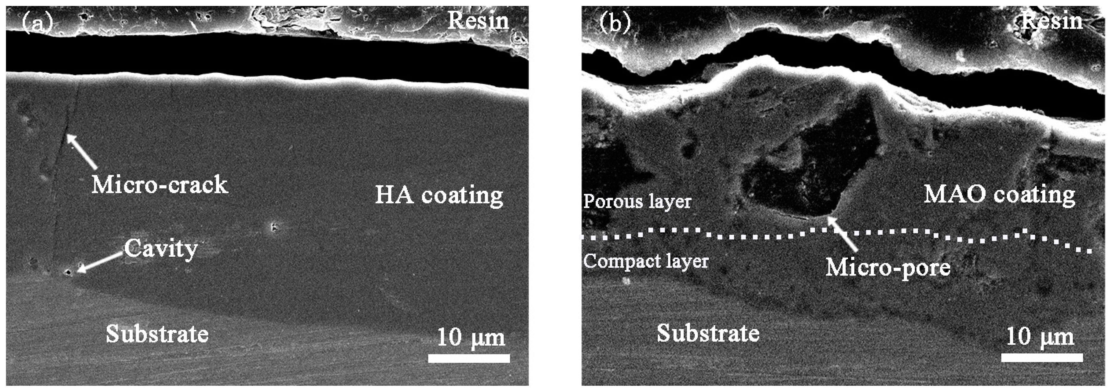
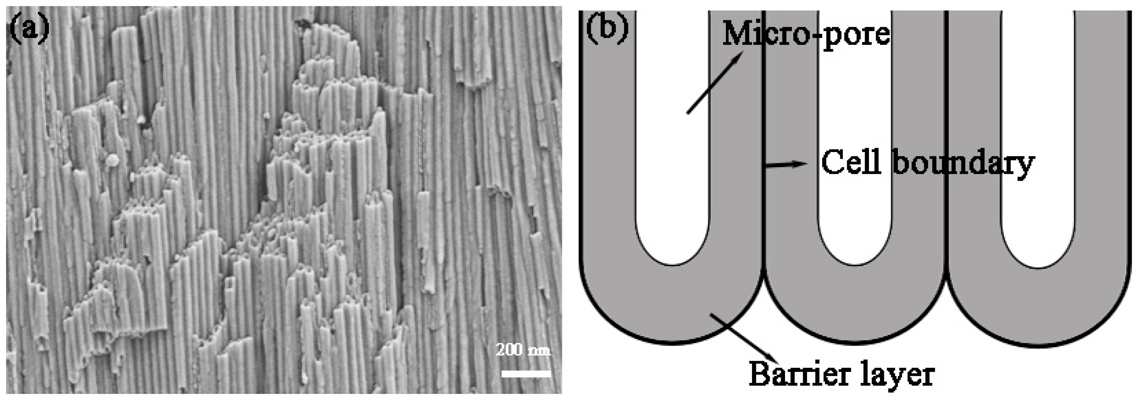
The cross-section morphology of the HA and MAO coatings are shown in Figure 2. The thickness of these two coatings was 27 ± 3 μm. Due to the excessive growth of the coating in the partial discharging region, the surface and interface of MAO coating were uneven, while the HA coating was flat, but it revealed much higher bonding strength between substrate and the MAO coating. There are two obvious layers in the MAO coating: a compact inner layer (about 5–12 μm) and a loose porous outer layer. While, the micro-pores in outer layer were much larger than that in the inner layer. This meant the inner layer was more compact than the outer layer due to less influence of the cold electrolyte. Figure 2a shows the cross-section morphology of the HA coating, and, due to conventional polishing with hard SiC emery papers, the micro-pores present in the HA coating that is observed in the surface (Figure 1a) had been destroyed [14]. Figure 3a shows the cross-section morphology of the HA coating without polishing, cylindrical cells with micro-pores along their length spread perpendicularly to the surface of the substrate and grew creating a porous layer. There is a widespread agreement that a thin barrier layer (in the illustration Figure 3b) at the base of each pore, which adheres to the metal substrate, is about 10–100 nm [26,27,28]. A micro-crack throughout the entire coating in the vertical direction in Figure 2a could be due to the weak junctions along the cylindrical oxide cell boundaries.
Although the micro-pores in the MAO coating were larger than that in the HA coating, they were not connected, or went throughout the coating, like that in the HA coating. MAO was a repetitive process as follows: micro-arc discharging-breakdown and melting-solidification and reconstruction. As a result, most of the discharge defects formed in the early stage will be covered by the product of the next discharge melting. In summary, the MAO coating is more effective in isolating the substrate from the corrosive environment.
3.2. Phase Composition
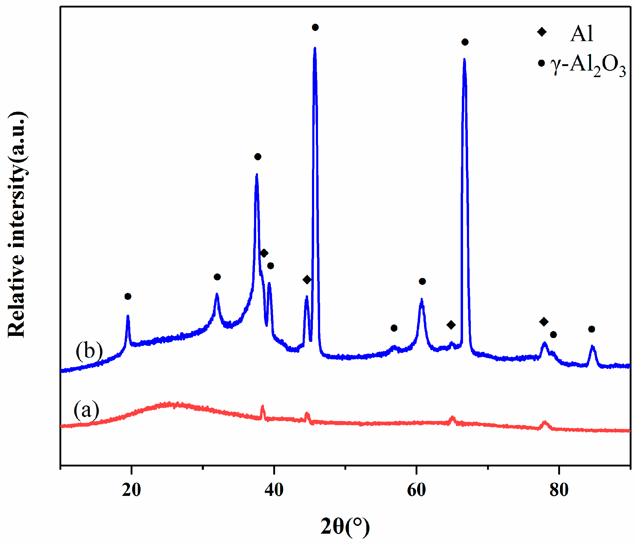
The XRD patterns of HA and MAO coatings are shown in Figure 4. It can be found that the pattern (Figure 4a) of the HA coating consists of very broad peaks (2θ = 18–37°) typical of amorphous materials due to oxide hydration [22], while the MAO coating was composed of γ-Al2O3 in Figure 4b. When molten alumina was ejected from the discharge micro-pores, it contacted the cold electrolyte directly and inclined to form crystalline Al2O3. The presence of the aluminum peak in the two coatings could be caused by the penetration of X-rays into the substrate [26].
3.3. Electrochemical Corrosion Behavior
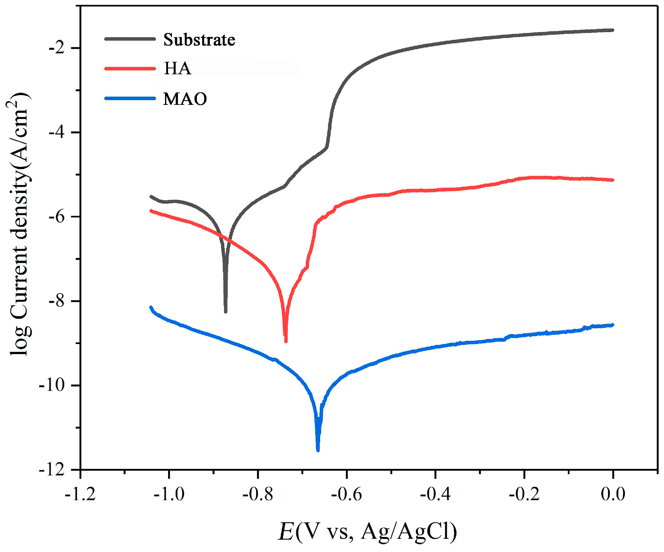
Figure 5 illustrates the potentiodynamic polarization curves of samples. When compared with the substrate, the corrosion potential (Ecorr) of the coatings both moved to positive direction and the Ecorr of the MAO coating was much more positive. The Ecorr and the corrosion current density (icorr) are tabulated in Table 2. The icorr value of the HA sample dropped one order of magnitude as compared to that of the substrate. Additionally, the icorr of the MAO simple was three orders of magnitude lower than that of the HA one. In summary, the MAO technique is much more useful to enhance the corrosion resistance of the substrate.
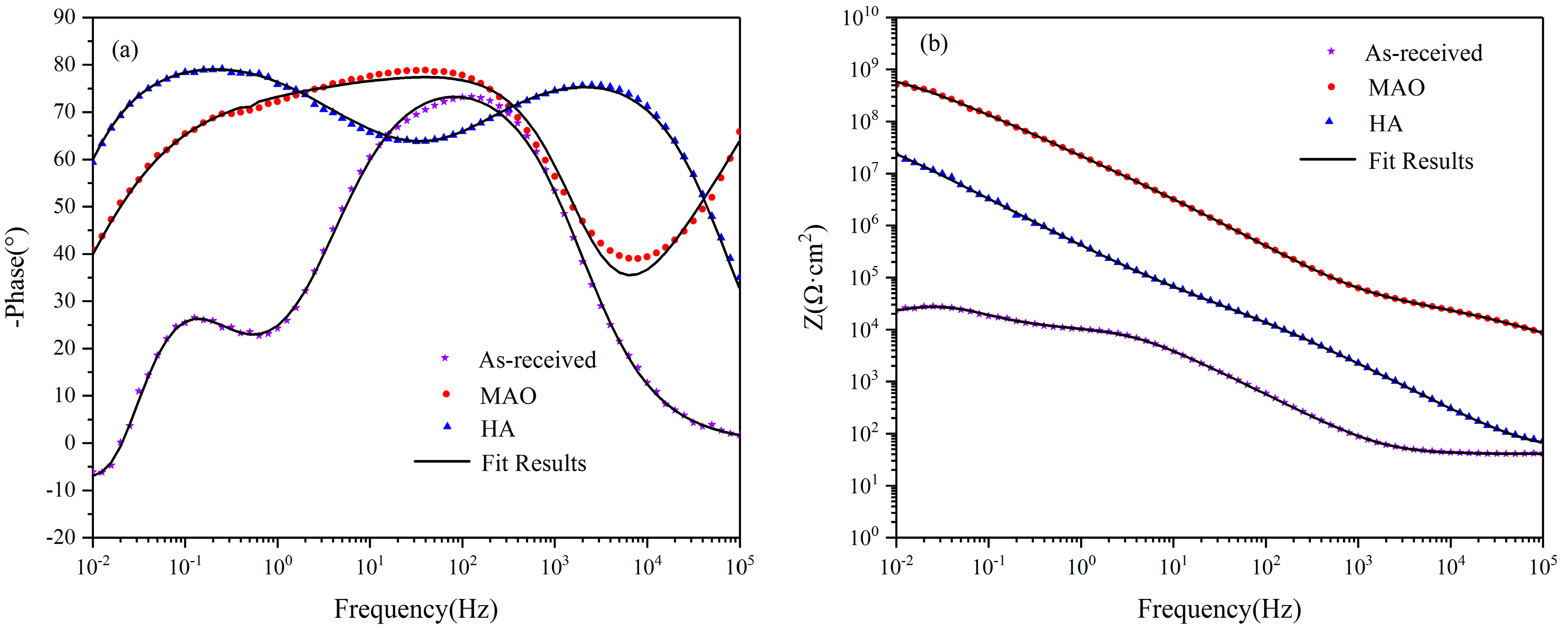
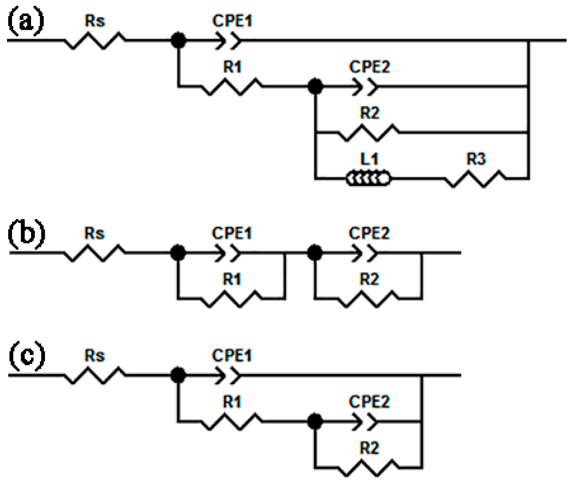
The EIS tests were took for further study of electrochemical corrosion behavior of the coatings. Figure 6 reveals the EIS (Bode) plots of the substrate, and HA- and MAO-treated 7050 Al alloy in the 3.5 wt % NaCl solution. There is a high frequency and an intermediate frequency capacitive reactance arc and a low-frequency impedance arc in the Bode phase angle plot of the substrate alloy. These arcs correspond to three time constants. The equivalent circuit model is exhibited in Figure 7a to fit the EIS plots. In this model, Rs is the resistance of solution. R1 is the resistance of natural oxide film and paralleled with a phase element CPE1. R2 represents the resistance of charge transfer on the metal surface and is paralleled with a phase element CPE2. The emergence of the impedance arc presents that the localized corrosion had happened. It is represented by the resistance R3 and inductance L. There are two time constants in the Bode phase angle plot of the HA coating. The one at high-frequency corresponds to the porous outer layer resistance (R1) and the phase element CPE1, and the another one at low-frequency corresponds to the barrier inner layer resistance (R2) and the phase element CPE2. Thus, a model in Figure 7b is used to fit the EIS plots of the HA coating. There are two time constants in the Bode phase angle plot of the MAO coating. A model in Figure 7c is used to fit the EIS plots. R1 in parallel with CPE1 and R2 in parallel with CPE2 are on behalf of the loose porous outer layer and the compact inner layer of the MAO coating, respectively.
The fitted values of the circuit elements are listed in Table 3. No matter the HA coating or the MAO coating, the values of R1 and R2 were much higher than that of the substrate, and the value of R2 was much higher than that of R1. This indicated that both the HA and the MAO treatment had effects on protecting the substrate materials against the corrosion, and the inner layer presented a much more fortified barrier for the diffusion of the corrosive ions. After the HA treatment, the value of R1 (5.23 × 10⁴) was slightly higher than that of the MAO coating (4.06 × 10⁴). This result was related to the larger micro-pores in the MAO loose porous outer layer. However, the value of R2 (1.11 × 10⁹) increased by almost two orders of magnitude than that of the HA coating (6.18 × 10⁷). This improvement was due to the fact that the dense inner layer in the MAO coating was at the micron scale while the barrier inner layer in the HA coating was at the nanoscale. In conclusion, the MAO coating significantly increased the corrosion resistance of the substrate alloy.
3.4. Neutral Salt Spray Test (NSST)
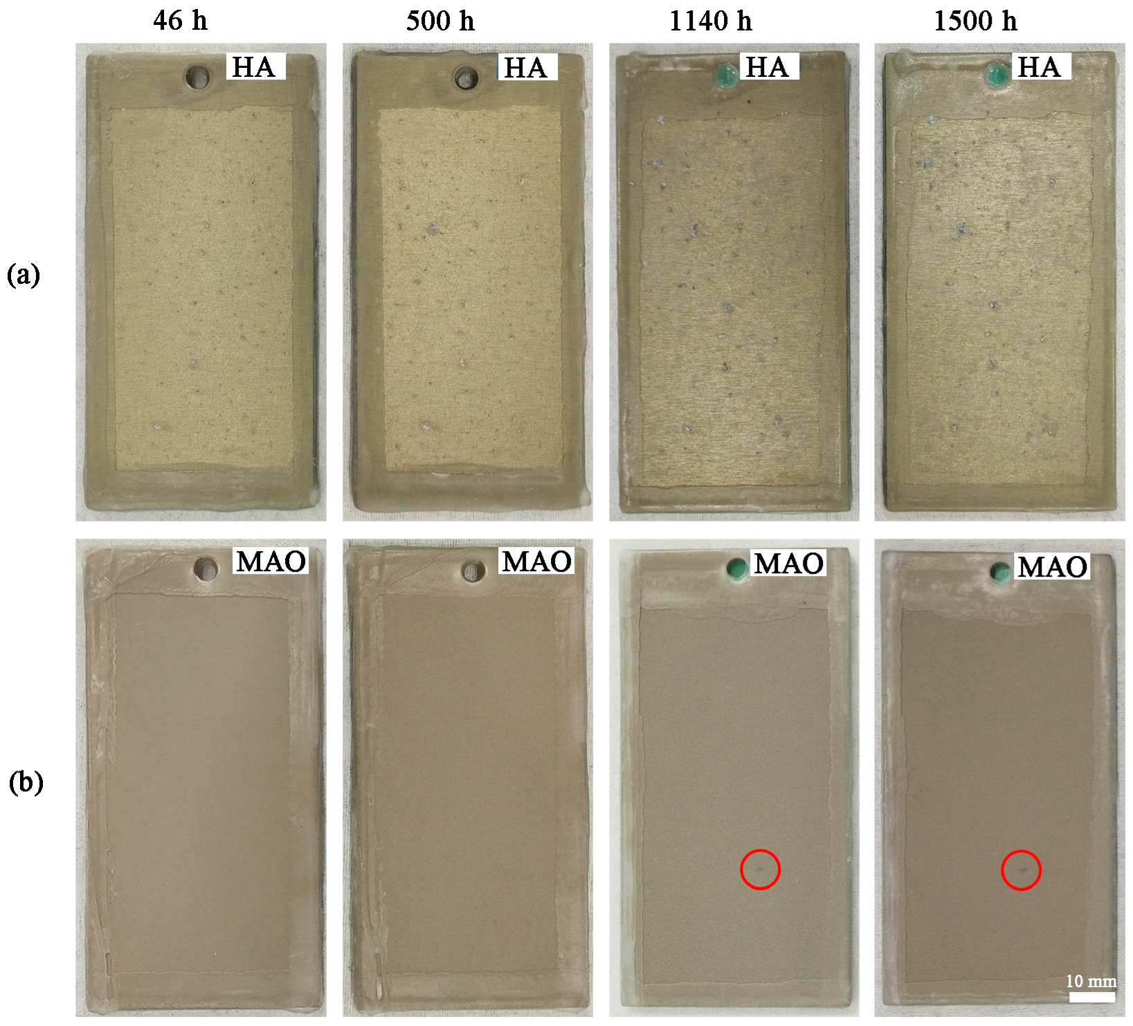
The long-term corrosion behavior of samples was further studied by NSST. Figure 8 exhibits digital photos of HA- and MAO-treated samples in the course of the test. Slight corrosion pitting emerged on the surface of the HA sample after 46 h (Figure 8a). Lasting to 1500 h, the number of corrosion pits increased obviously. Conversely, in Figure 8b, there was slight corrosion on the MAO coating after 1140 h and, until the end of the test, the corroded area did not expand. The results shown MAO treatment significantly improved the long-term corrosion resistance of 7050 aluminium alloy.
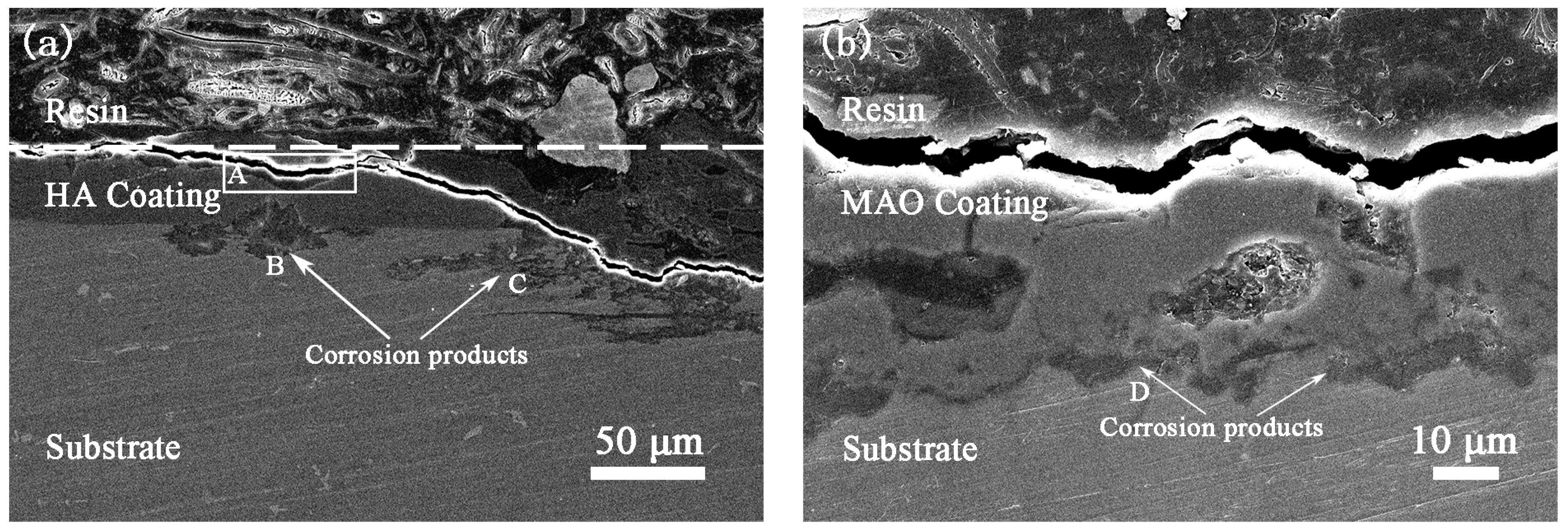
The cross-section morphology (Figure 9) of the HA and MAO coatings after 1500 h NSST were analyzed so as to observe the corrosion features clearly. The thickness of the HA coating was 16–26 μm, when compared with Figure 2a, the HA coating became thinner and uneven in Box A of Figure 9a, while, the thickness of the MAO coating (23–29 μm) did not change a lot and the coating retained the original cross-section morphology in Figure 9b. These distinctions might be the result from different phase compositions of the coatings. Furthermore, as the defects (micro-pores and micro-cracks) that went through the entire outer layer and the thickness of the barrier layer was at the nanoscale order of magnitude, the corrosive ions reached the coating/substrate interface through straight defects channels quickly, and, thus, contributed to the corrosion of the substrate. As time went on, nearby corrosion products linked and gathered together (arrow B in Figure 9a) and the accumulated corrosion products generated high stress to jack up the coating. Additionally, after the film had partly fallen off, the corrosion continued to spread downward, so that the corrosion depth of the matrix would increase and the coating lost the function of protection. On the other hand, the corrosion would spread along the interface and destroy the coating nearby (arrow C in Figure 9a). So on, severe corrosion damage appeared on the HA-treated alloy in short term. When compared with Figure 9a, a relatively small quantity of the corrosion products (arrow D in Figure 9b) were accumulated at the interface of the MAO coating and they reduced the extrusion damage to the coating. Because the MAO coating did not peel off from the substrate, the corrosion depth of the MAO-treated alloy was smaller than that of the HA-treated one. This improvement was due to the fact that the micro-pores in the loose porous outer layer did not join together and the inner barrier layer provided a compact barrier, and all of this made the path of the corrosive ions becomes complicated and delayed the time of corrosive ions’ arrival at the substrate. Thus, the amount of corrosion products at the interface of the MAO coating is less than that of the HA coating at the same corrosion time. Meanwhile, the higher bonding strength between the substrate and the MAO coating made the coating difficult to top up.
Thus, the substrate under the MAO coating suffered from relatively slight destroy, when compared to that under the HA coating. As a result, the MAO-treated specimen displayed better corrosion resistance than the HA-treated one.
4. Conclusions
- MAO and HA coatings with 27 ± 3 μm thickness were fabricated onto the surface of 7050 Al alloy, respectively. The MAO coating, mainly composed of γ-Al2O3, was much more effective to isolate the substrate from the corrosive environment than the HA one, due to the amorphous composition and the penetrating defects in the HA coating.
- The MAO technology displayed more excellent electrochemical corrosion resistance. Compared with the HA coating, the corrosion potential (Ecorr), and corrosion current density (icorr) of the MAO coating increased and decreased, respectively. Furthermore, the value of R2 of the MAO coating was two orders of magnitude higher than that of HA coating.
- The NSST revealed that the time when the HA coating was corroded was 46 h, while the MAO coating was 1140 h. After 1500 h, the HA coating was extruded and peeled, but the MAO coating still provided good protection to the substrate.
- The far superior protection of the MAO coating was due to the crystalline compositions and the strong interfacial adhesion. Furthermore, the blind defects in the MAO coating made the path of the corrosive ions become complicated, and the compact inner layer presented a more fortified barrier for the diffusion of corrosive ions.
Acknowledgments
The authors gratefully acknowledge the financial support of the project from the National Natural Science Foundation of China (Nos. 51571114, 51401106), the Natural Science Foundation of Jiangsu Province (No. BK20130935) and the Priority Academic Program Development of Jiangsu Higher Education Institutions (PAPD).
Author Contributions
The work presented here was carried out in collaboration between all authors. Hongtao Li, Bailing Jiang and Lianlian Shao conceived and designed the experiments; Lianlian Shao and Xin Gu performed the experiments; Hongtao Li, Lianlian Shao and Cancan Liu analyzed the data; Dichun Chen contributed analysis tools; Lianlian Shao wrote the paper.
Conflicts of Interest
The authors declare no conflict of interest.
References
- Heinz, A.; Haszler, A.; Keidel, C.; Moldenhauer, S.; Benedictus, R.; Miller, W.S. Recent development in aluminium alloys for aerospace applications. Mater. Sci. Eng. A Struct. Mater. Prop. Microstruct. Process. 2000, 280, 102–107. [Google Scholar] [CrossRef]
- Wloka, J.; Virtanen, S. Influence of scandium on the pitting behaviour of Al-Zn-Mg-Cu alloys. Acta Mater. 2007, 55, 6666–6672. [Google Scholar] [CrossRef]
- Ramgopal, T.; Gouma, P.I.; Frankel, G.S. Role of grain-boundary precipitates and solute-depleted zone on the intergranular corrosion of aluminum alloy 7150. Corros. Sci. 2002, 58, 687–697. [Google Scholar] [CrossRef]
- Peng, G.S.; Chen, K.H.; Chen, S.Y.; Fang, H.C. Influence of dual-RRA temper on the exfoliation corrosion and electrochemical behavior of Al-Zn-Mg-Cu alloy. Mater. Corros. Werkst. Korros. 2013, 64, 284–289. [Google Scholar] [CrossRef]
- Lin, Y.C.; Zhang, J.; Chen, M.; Zhou, Y.; Ma, X. Electrochemical corrosion behaviors of a stress-aged Al-Zn-Mg-Cu alloy. J. Mater. Res. 2016, 31, 2493–2505. [Google Scholar] [CrossRef]
- Franco, M.; Krishna, H.T.; Pillai, A.M.; Rajendra, A.; Sharma, A.K. A Comparative Study on the Corrosion Behaviour of Hard Anodic Coatings on AA 6061 Obtained Using DC and Pulsed DC Power Sources. Acta Metall. Sin. 2013, 26, 647–656. [Google Scholar] [CrossRef]
- Konno, H.; Utaka, K.; Furuichi, R. A two step anodizing process of aluminium as a means for improving the chemical and physical properties of oxide films. Corros. Sci. 1996, 38, 2247–2256. [Google Scholar] [CrossRef]
- Zuo, Y.; Zhao, P.H.; Zhao, J.M. The influences of sealing methods on corrosion behavior of anodized aluminum alloys in NaCl solutions. Surf. Coat. Technol. 2003, 166, 237–242. [Google Scholar] [CrossRef]
- Bozza, A.; Giovanardi, R.; Manfredini, T.; Mattioli, P. Pulsed Current effect on hard anodizing process of 7075-T6 aluminium alloy. Surf. Coat. Technol. 2015, 270, 139–144. [Google Scholar] [CrossRef]
- Fratila-Apachitei, L.E.; Duszczyk, J.; Katgerman, L. AlSi(Cu) anodic oxide layers formed in H2SO4 at low temperature using different current waveforms. Surf. Coat. Technol. 2003, 165, 232–240. [Google Scholar] [CrossRef]
- Wen, L.; Wang, Y.; Zhou, Y.; Guo, L.; Ouyang, J. Microstructure and corrosion resistance of modified 2024 Al alloy using surface mechanical attrition treatment combined with microarc oxidation process. Corros. Sci. 2011, 53, 473–480. [Google Scholar] [CrossRef]
- Ma, A.; Lu, F.; Zhou, Q.; Jiang, J.; Song, D.; Chen, J.; Zheng, Y. Formation and Corrosion Resistance of Micro-Arc Oxidation Coating on Equal-Channel Angular Pressed AZ91D Mg Alloy. Metals 2016, 6, 308. [Google Scholar] [CrossRef]
- Xu, L.; Ding, J.; Xu, X.; Niu, X.; Li, B.; Cheng, G. Wettability and Corrosion Resistance of Ultrafine-Grained Titanium by Micro-arc Oxidation. Rare Met. Mater. Eng. 2015, 44, 3100–3104. [Google Scholar]
- Krishna, L.R.; Purnima, A.S.; Sundararajan, G. A comparative study of tribological behavior of microarc oxidation and hard-anodized coatings. Wear 2006, 261, 1095–1101. [Google Scholar] [CrossRef]
- Wen, L.; Wang, Y.; Zhou, Y.; Ouyang, J.; Guo, L.; Jia, D. Corrosion evaluation of microarc oxidation coatings formed on 2024 aluminium alloy. Corros. Sci. 2010, 52, 2687–2696. [Google Scholar] [CrossRef]
- Arunnellaiappan, T.; Babu, N.K.; Krishna, L.R.; Rameshbabu, N. Influence of frequency and duty cycle on microstructure of plasma electrolytic oxidized AA7075 and the correlation to its corrosion behavior. Surf. Coat. Technol. 2015, 280, 136–147. [Google Scholar] [CrossRef]
- Wang, Y.Q.; Deng, Y.Z.; Shao, Y.W.; Wang, F.H. New sealing treatment of microarc oxidation coating. Surf. Eng. 2014, 30, 31–35. [Google Scholar] [CrossRef]
- Yang, H.; Wang, X.; Wang, Y.; Wang, Y.; Zhang, Z. Microarc Oxidation Coating Combined with Surface Pore-Sealing Treatment Enhances Corrosion Fatigue Performance of 7075-T7351 Al Alloy in Different Media. Materials 2017, 10, 609. [Google Scholar] [CrossRef] [PubMed]
- Xiang, N.; Song, R.G.; Wang, C.; Mao, Q.Z.; Ge, Y.J.; Ding, J.H. Formation of corrosion resistant plasma electrolytic oxidation coatings on aluminium alloy with addition of sodium tungstate species. Corros. Eng. Sci. Technol. 2016, 51, 146–154. [Google Scholar] [CrossRef]
- Chen, Q.; Jiang, Z.; Tang, S.; Dong, W.; Tong, Q.; Li, W. Influence of graphene particles on the micro-arc oxidation behaviors of 6063 aluminum alloy and the coating properties. Appl. Surf. Sci. 2017, 423, 939–950. [Google Scholar] [CrossRef]
- Liu, J.; Li, M.; Li, S.; Huang, M. Effect of the microstructure of Al 7050-T7451 on anodic oxide formation in sulfuric acid. Int. J. Miner. Metall. Mater. 2009, 16, 432–438. [Google Scholar] [CrossRef]
- Patermarakis, G. Development of a theory for the determination of the composition of the anodizing solution inside the pores during the growth of porous anodic Al2O3 films on aluminium by a transport phenomenon analysis. J. Electroanal. Chem. 1998, 447, 25–41. [Google Scholar] [CrossRef]
- Li, Y.; Ling, Z.; Hu, X.; Liu, Y.; Chang, Y. Investigation of intrinsic mechanisms of aluminium anodization processes by analyzing the current density. RSC Adv. 2012, 2, 5164–5171. [Google Scholar] [CrossRef]
- Azimi, H.A.R.; Zarei, M.; Rafati, A.; Noormohammadi, M. Fabrication of self-ordered nanoporous alumina with 500–750 nm interpore distances using hard anodization in phosphoric/oxalic acid mixtures. J. Porous Mater. 2016, 23, 357–363. [Google Scholar] [CrossRef]
- Liu, C.; Liang, J.; Zhou, J.; Li, Q.; Peng, Z.; Wang, L. Characterization and corrosion behavior of plasma electrolytic oxidation coated AZ91-T6 magnesium alloy. Surf. Coat. Technol. 2016, 304, 179–187. [Google Scholar] [CrossRef]
- Skoneczny, W. Model of structure of Al2O3 layer obtained via hard anodising method. Surf. Eng. 2001, 17, 389–392. [Google Scholar] [CrossRef]
- Garcia-Vergara, S.J.; LeClere, D.; Hashimoto, T.; Habazaki, H.; Skeldon, R.; Thompson, G.E. Optimized observation of tungsten tracers for investigation of formation of porous anodic alumina. Electrochim. Acta 2009, 54, 6403–6411. [Google Scholar] [CrossRef]
- Lerner, L.M. Hard anodising of aerospace aluminium alloys. Trans. Inst. Met. Finish. 2010, 88, 21–24. [Google Scholar] [CrossRef]
Figure 1.
Surface scanning electron microscope (SEM) micrographs of the HA coating (a,c,d) and the MAO coating (b,e) on the 7050 Al alloy.
Figure 1.
Surface scanning electron microscope (SEM) micrographs of the HA coating (a,c,d) and the MAO coating (b,e) on the 7050 Al alloy.

Figure 2.
Cross-sectional SEM micrographs of the HA coating (a) and the MAO coating (b) on the 7050 Al alloy.
Figure 2.
Cross-sectional SEM micrographs of the HA coating (a) and the MAO coating (b) on the 7050 Al alloy.

Figure 3.
Cross-sectional SEM micrographs of the HA coating with cylindrical cells (a) and an illustration of barrier layer (b).
Figure 3.
Cross-sectional SEM micrographs of the HA coating with cylindrical cells (a) and an illustration of barrier layer (b).

Figure 4.
X-ray diffraction (XRD) patterns of the HA (a) and the MAO (b) coatings on 7050 Al alloys.
Figure 4.
X-ray diffraction (XRD) patterns of the HA (a) and the MAO (b) coatings on 7050 Al alloys.

Figure 5.
Potentiodynamic polarization curves of the substrate, and the HA- and MAO-treated 7050 Al alloy in 3.5 wt % NaCl solution.
Figure 5.
Potentiodynamic polarization curves of the substrate, and the HA- and MAO-treated 7050 Al alloy in 3.5 wt % NaCl solution.

Figure 6.
Electrochemical impedance spectroscopy and fitting results of the substrate, and the HA- and the MAO-treated 7050 Al alloy in 3.5 wt % NaCl solution. (a) Phase angle; (b) Impedance modulus.
Figure 6.
Electrochemical impedance spectroscopy and fitting results of the substrate, and the HA- and the MAO-treated 7050 Al alloy in 3.5 wt % NaCl solution. (a) Phase angle; (b) Impedance modulus.

Figure 7.
Corresponding equivalent circuits for fitting impedance date of the substrate (a); and the HA- (b); and, MAO- (c) treated 7050 Al alloy.
Figure 7.
Corresponding equivalent circuits for fitting impedance date of the substrate (a); and the HA- (b); and, MAO- (c) treated 7050 Al alloy.

Figure 8.
Photographs of the HA- (a) and the MAO-treated (b) 7050 Al alloy after a neutral salt spray test (NSST) for different times.
Figure 8.
Photographs of the HA- (a) and the MAO-treated (b) 7050 Al alloy after a neutral salt spray test (NSST) for different times.

Figure 9.
Cross-section SEM micrographs of the HA- (a) and the MAO-treated (b) 7050 Al alloy after a neutral salt spray test in 5 wt % NaCl solution for 1500 h.
Figure 9.
Cross-section SEM micrographs of the HA- (a) and the MAO-treated (b) 7050 Al alloy after a neutral salt spray test in 5 wt % NaCl solution for 1500 h.


Table 1.
Experimental conditions employed for depositing the hard anodization (HA) and micro-arc oxidation (MAO) coatings.
Table 1.
Experimental conditions employed for depositing the hard anodization (HA) and micro-arc oxidation (MAO) coatings.
| Nomenclature | MAO | HA |
|---|---|---|
| Electrolyte bath | Sodium hexametaphosphate 40 g/L Sodium silicate 5 g/L Sodium tungstate 3 g/L | Sulfuric acid 15 wt % |
| Type of power supply | DC pulse | DC |
| Duty cycle (%) | 4 | - |
| Frequency (Hz) | 500 | - |
| Bath temperrature (°C) | 18–30 | 0–5 |
| Current density (A/dm2) | 2.5 | 2.5 |
| Voltage, Vrms | 0–550 | 0–25 |
| Processing time (min) | 80 | 40 |
Table 2.
Fitting results of potentiodynamic polarization tests.
| Specimens | Ecorr (mV vs. Ag/AgCl) | icorr (A/cm2) |
|---|---|---|
| Substrate | −874 | 1.11 × 10⁻⁶ |
| HA | −732 | 1.17 × 10⁻⁷ |
| MAO | −665 | 2.10 × 10⁻¹⁰ |
Table 3.
Electrochemical impedance spectroscopy (EIS) fitting results for specimens in 3.5 wt % NaCl solution.
Table 3.
Electrochemical impedance spectroscopy (EIS) fitting results for specimens in 3.5 wt % NaCl solution.
| Specimens | CPE1 | R1 (Ω·cm2) | CPE2 | R2 (Ω·cm2) | L1 (Ω·s·cm2) | R3 (Ω·cm2) |
|---|---|---|---|---|---|---|
| substrate | 5.76 × 10⁻⁶ (0.89) | 1.12 × 10⁴ | 1.15 × 10⁻⁴ (0.84) | 2.12 × 10⁴ | 2.85 × 10⁵ | 1.62 × 10⁴ |
| HA | 2.51 × 10⁻⁷ (0.90) | 5.23 × 10⁴ | 4.66 × 10⁻⁷ (0.91) | 6.18 × 10⁷ | - | - |
| MAO | 6.67 × 10⁻⁹ (0.72) | 4.06 × 10⁴ | 3.82 × 10⁻⁹ (0.95) | 1.11 × 10⁹ | - | - |
© 2018 by the authors. Licensee MDPI, Basel, Switzerland. This article is an open access article distributed under the terms and conditions of the Creative Commons Attribution (CC BY) license (http://creativecommons.org/licenses/by/4.0/).
Share and Cite
MDPI and ACS Style
Shao, L.; Li, H.; Jiang, B.; Liu, C.; Gu, X.; Chen, D. A Comparative Study of Corrosion Behavior of Hard Anodized and Micro-Arc Oxidation Coatings on 7050 Aluminum Alloy. Metals 2018, 8, 165. https://doi.org/10.3390/met8030165
AMA Style
Shao L, Li H, Jiang B, Liu C, Gu X, Chen D. A Comparative Study of Corrosion Behavior of Hard Anodized and Micro-Arc Oxidation Coatings on 7050 Aluminum Alloy. Metals. 2018; 8(3):165. https://doi.org/10.3390/met8030165
Chicago/Turabian StyleShao, Lianlian, Hongtao Li, Bailing Jiang, Cancan Liu, Xin Gu, and Dichun Chen. 2018. "A Comparative Study of Corrosion Behavior of Hard Anodized and Micro-Arc Oxidation Coatings on 7050 Aluminum Alloy" Metals 8, no. 3: 165. https://doi.org/10.3390/met8030165
Note that from the first issue of 2016, this journal uses article numbers instead of page numbers. See further details here.