
Hysteresis in As-Synthesized MoS2 Transistors: Origin and Sensing Perspectives

 , ,
, ,  , , , , , and
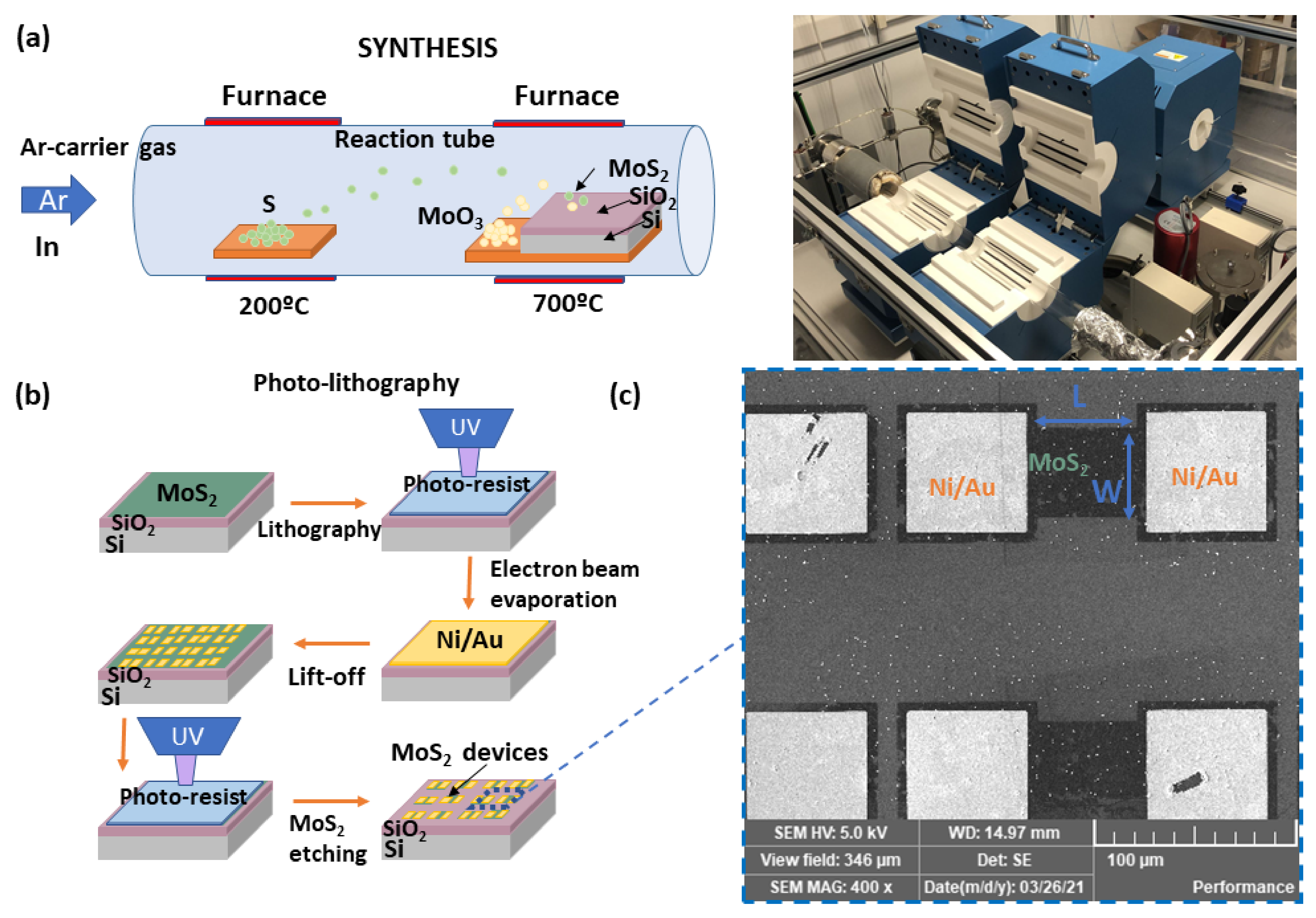
Abstract
:1. Introduction
2. Materials and Methods
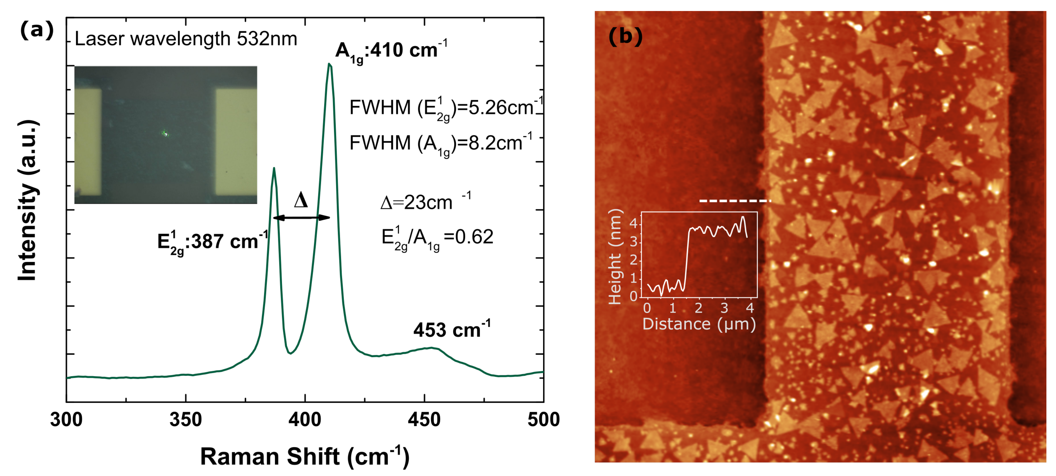
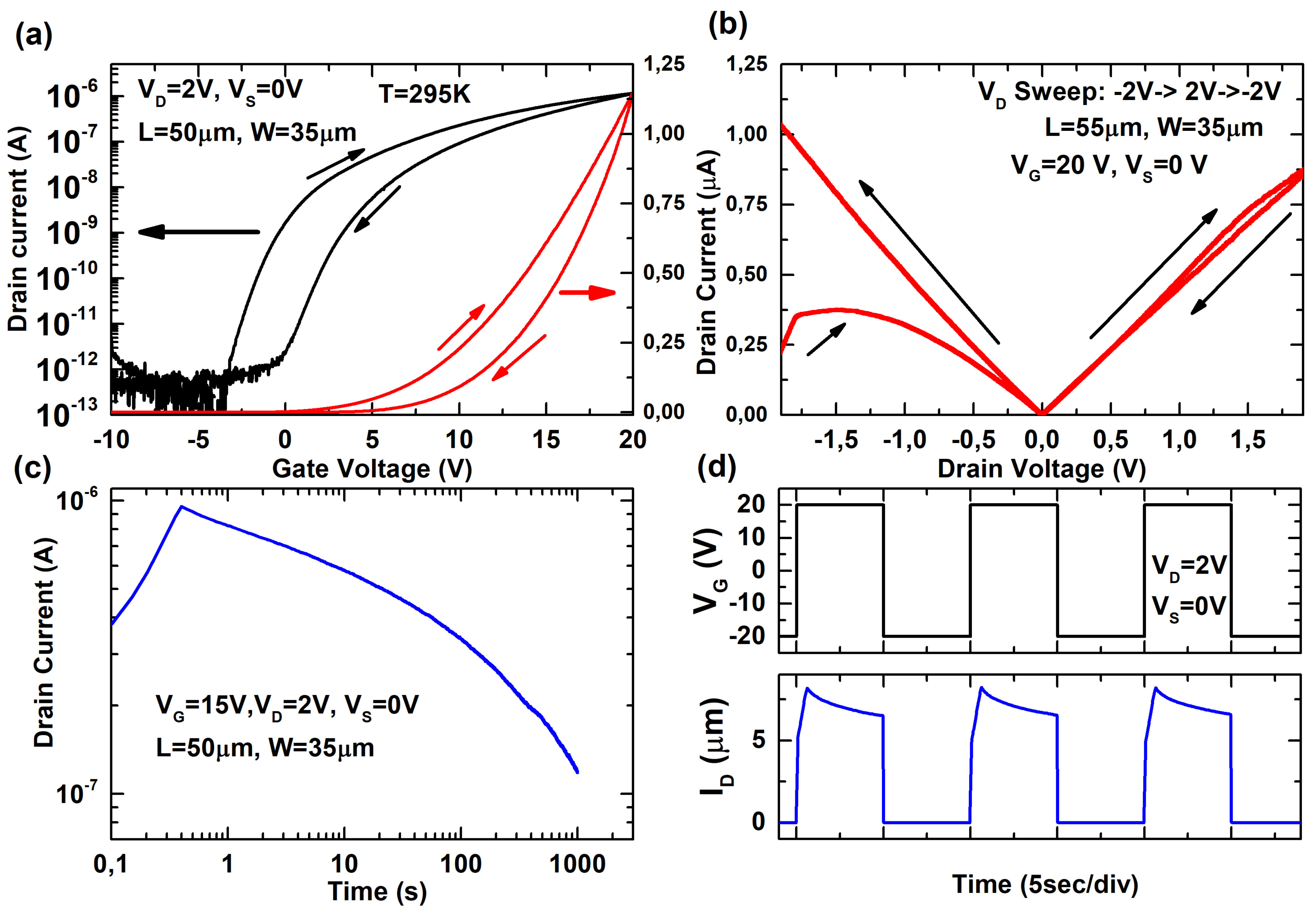
3. Results
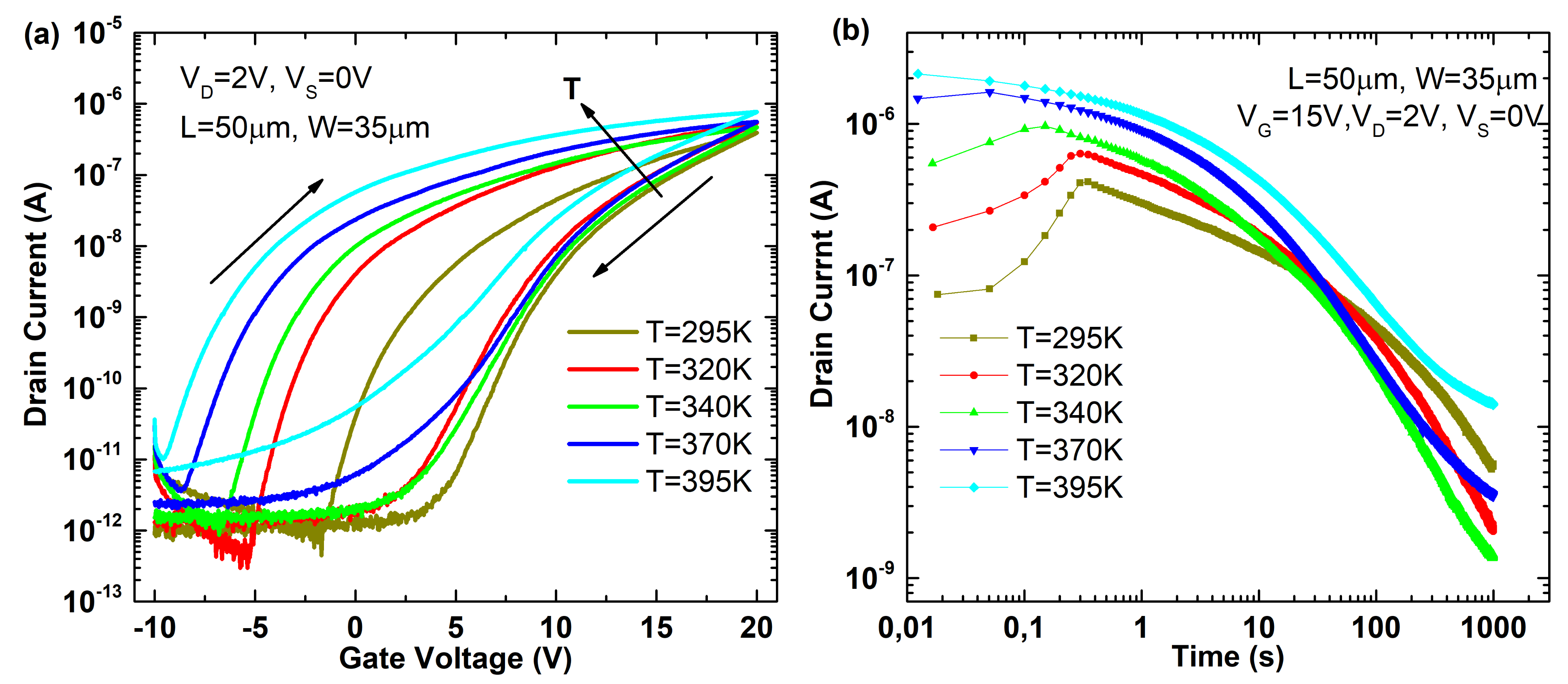
4. Discussion and Application
5. Conclusions
Author Contributions
Funding
Acknowledgments
Conflicts of Interest
References
- Frank, D.; Dennard, R.; Nowak, E.; Solomon, P.; Taur, Y.; Wong, H.-S.P. Device scaling limits of Si MOSFETs and their application dependencies. Proc. IEEE 2001, 89, 259–288. [Google Scholar] [CrossRef]
- Rieger, M.L. Retrospective on VLSI value scaling and lithography. J. Micro/Nanolithography MEMS MOEMS 2019, 18, 1. [Google Scholar] [CrossRef]
- Narayanan, V. High-k/Metal Gates- from research to reality. In Proceedings of the 2007 International Workshop on Physics of Semiconductor Devices, Mumbai, India, 16–20 December 2007; pp. 42–45. [Google Scholar] [CrossRef]
- Maleville, C. Engineered substrates for Moore and more than Moore’s law: Device scaling: Entering the substrate era. In Proceedings of the 2015 IEEE SOI-3D-Subthreshold Microelectronics Technology Unified Conference, S3S 2015, Rohnert Park, CA, USA, 5–8 October 2015. [Google Scholar] [CrossRef]
- Samavedam, S.B.; Ryckaert, J.; Beyne, E.; Ronse, K.; Horiguchi, N.; Tokei, Z.; Radu, I.; Bardon, M.G.; Na, M.H.; Spessot, A.; et al. Future logic scaling: Towards atomic channels and deconstructed chips. In Proceedings of the Technical Digest—International Electron Devices Meeting, (IEDM 2020), San Francisco, CA, USA, 12–18 December 2020; pp. 1.1.1–1.1.10. [Google Scholar] [CrossRef]
- Del Alamo, J.A.; Antoniadis, D.A.; Lin, J.; Lu, W.; Vardi, A.; Zhao, X. III–V MOSFETs for Future CMOS. In Proceedings of the 2015 IEEE Compound Semiconductor Integrated Circuit Symposium (CSICS 2015), New Orleans, LA, USA, 11–14 October 2015; pp. 1–4. [Google Scholar] [CrossRef]
- Heyns, M.; Tsai, W. Ultimate scaling of CMOS logic devices with Ge and III–V materials. MRS Bull. 2009, 34, 485–488. [Google Scholar] [CrossRef]
- Navarro, C.; Karg, S.; Marquez, C.; Navarro, S.; Convertino, C.; Zota, C.; Czornomaz, L.; Gamiz, F. Capacitor-less dynamic random access memory based on a III–V transistor with a gate length of 14 nm. Nat. Electron. 2019, 2, 412–419. [Google Scholar] [CrossRef]
- Novoselov, K.S.; Geim, A.K.; Morozov, S.V.; Jiang, D.; Zhang, Y.; Dubonos, S.V.; Grigorieva, I.V.; Firsov, A.A. Electric Field Effect in Atomically Thin Carbon Films. Science 2004, 306, 666–669. [Google Scholar] [CrossRef] [PubMed] [Green Version]
- Novoselov, K.S.; Jiang, D.; Schedin, F.; Booth, T.J.; Khotkevich, V.V.; Morozov, S.V.; Geim, A.K. Two-dimensional atomic crystals. Proc. Natl. Acad. Sci. USA 2005, 102, 10451–10453. [Google Scholar] [CrossRef] [PubMed] [Green Version]
- Salazar, N.; Marquez, C.; Gamiz, F. Synthesis of graphene and other two-dimensional materials. In 2D Materials for Nanophotonics; Elsevier: Amsterdam, The Netherlands, 2021; pp. 1–79. [Google Scholar] [CrossRef]
- Chhowalla, M.; Jena, D.; Zhang, H. Two-dimensional semiconductors for transistors. Nat. Rev. Mater. 2016, 1, 1–15. [Google Scholar] [CrossRef]
- Mitta, S.B.; Choi, M.S.; Nipane, A.; Ali, F.; Kim, C.; Teherani, J.T.; Hone, J.; Yoo, W.J. Electrical characterization of 2D materials-based field-effect transistors. 2D Mater. 2021, 8, 012002. [Google Scholar] [CrossRef]
- Yu, Z.G.; Yakobson, B.I.; Zhang, Y.W. Realizing Indirect-to-Direct Band Gap Transition in Few-Layer Two-Dimensional MX2 (M = Mo, W; X = S, Se). ACS Appl. Energy Mater. 2018, 1, 4115–4121. [Google Scholar] [CrossRef]
- Yu, C. The 3rd dimension-More Life for Moore’s Law. In Proceedings of the 2006 International Microsystems, Package, Assembly Conference Taiwan, Taipei, Taiwan, 18–20 October 2006; No. 8. pp. 1–6. [Google Scholar] [CrossRef]
- Banerjee, K.; Souri, S.J.; Kapur, P.; Saraswat, K.C. 3-D ICs: A novel chip design for improving deep-submieroraeter interconnect performance and systems-on-chip integration and systems-on-chlp integration. Proc. IEEE 2001, 89, 602–632. [Google Scholar] [CrossRef] [Green Version]
- Kang, J.; Cao, W.; Xie, X.; Sarkar, D.; Liu, W.; Banerjee, K. Graphene and beyond-graphene 2D crystals for next-generation green electronics. In Proceedings of the Micro- and Nanotechnology Sensors, Systems, and Applications VI, Baltimore, MD, USA, 5–9 May 2014. [Google Scholar] [CrossRef]
- Jiang, J.; Parto, K.; Cao, W.; Banerjee, K. Ultimate Monolithic-3D Integration With 2D Materials: Rationale, Prospects, and Challenges. IEEE J. Electron Devices Soc. 2019, 7, 878–887. [Google Scholar] [CrossRef]
- Lo, C.L.; Helfrecht, B.A.; He, Y.; Guzman, D.M.; Onofrio, N.; Zhang, S.; Weinstein, D.; Strachan, A.; Chen, Z. Opportunities and challenges of 2D materials in back-end-of-line interconnect scaling. J. Appl. Phys. 2020, 128, 080903. [Google Scholar] [CrossRef]
- Bhattacharjee, S.; Caruso, E.; McEvoy, N.; Ó Coileáin, C.; O’Neill, K.; Ansari, L.; Duesberg, G.S.; Nagle, R.; Cherkaoui, K.; Gity, F.; et al. Insights into Multilevel Resistive Switching in Monolayer MoS2. ACS Appl. Mater. Interfaces 2020, 12, 6022–6029. [Google Scholar] [CrossRef]
- Samnakay, R.; Jiang, C.; Rumyantsev, S.L.; Shur, M.S.; Balandin, A.A. Selective chemical vapor sensing with few-layer MoS2 thin-film transistors: Comparison with graphene devices. Appl. Phys. Lett. 2015, 106, 1–6. [Google Scholar] [CrossRef] [Green Version]
- Late, D.J.; Huang, Y.K.; Liu, B.; Acharya, J.; Shirodkar, S.N.; Luo, J.; Yan, A.; Charles, D.; Waghmare, U.V.; Dravid, V.P.; et al. Sensing behavior of atomically thin-layered MoS2 transistors. ACS Nano 2013, 7, 4879–4891. [Google Scholar] [CrossRef]
- Huyghebaert, C.; Schram, T.; Smets, Q.; Kumar Agarwal, T.; Verreck, D.; Brems, S.; Phommahaxay, A.; Chiappe, D.; El Kazzi, S.; Lockhart de la Rosa, C.; et al. 2D materials: Roadmap to CMOS integration. In Proceedings of the 2018 IEEE International Electron Devices Meeting (IEDM), San Francisco, CA, USA, 1–5 December 2018; Volume 1, pp. 22.1.1–22.1.4. [Google Scholar] [CrossRef]
- Huang, J.K.; Pu, J.; Hsu, C.L.; Chiu, M.H.; Juang, Z.Y.; Chang, Y.H.; Chang, W.H.; Iwasa, Y.; Takenobu, T.; Li, L.J. Large-area synthesis of highly crystalline WSe2 monolayers and device applications. ACS Nano 2014, 8, 923–930. [Google Scholar] [CrossRef] [Green Version]
- Wang, J.; Yao, Q.; Huang, C.W.; Zou, X.; Liao, L.; Chen, S.; Fan, Z.; Zhang, K.; Wu, W.; Xiao, X.; et al. High Mobility MoS2 Transistor with Low Schottky Barrier Contact by Using Atomic Thick h-BN as a Tunneling Layer. Adv. Mater. 2016, 28, 8302–8308. [Google Scholar] [CrossRef]
- Illarionov, Y.Y.; Smithe, K.K.H.; Waltl, M.; Knobloch, T.; Pop, E.; Grasser, T. Improved Hysteresis and Reliability of MoS2 Transistors With High-Quality CVD Growth and Al2O3 Encapsulation. IEEE Electron Device Lett. 2017, 38, 1763–1766. [Google Scholar] [CrossRef]
- Illarionov, Y.Y.; Banshchikov, A.G.; Polyushkin, D.K.; Wachter, S.; Knobloch, T.; Thesberg, M.; Mennel, L.; Paur, M.; Stöger-Pollach, M.; Steiger-Thirsfeld, A.; et al. Ultrathin calcium fluoride insulators for two-dimensional field-effect transistors. Nat. Electron. 2019, 2, 230–235. [Google Scholar] [CrossRef]
- Bhattacharjee, S.; Ganapathi, K.L.; Nath, D.N.; Bhat, N. Surface State Engineering of Metal/MoS2 Contacts Using Sulfur Treatment for Reduced Contact Resistance and Variability. IEEE Trans. Electron Devices 2016, 63, 2556–2562. [Google Scholar] [CrossRef] [Green Version]
- Han, X.; Lin, J.; Liu, J.; Wang, N.; Pan, D. Effects of Hexagonal Boron Nitride Encapsulation on the Electronic Structure of Few-Layer MoS 2. J. Phys. Chem. C 2019, 123, 14797–14802. [Google Scholar] [CrossRef] [Green Version]
- Liu, H.; Li, D.; Ma, C.; Zhang, X.; Sun, X.; Zhu, C.; Zheng, B.; Zou, Z.; Luo, Z.; Zhu, X.; et al. Van der Waals epitaxial growth of vertically stacked Sb2Te3/MoS2 p–n heterojunctions for high performance optoelectronics. Nano Energy 2019, 59, 66–74. [Google Scholar] [CrossRef]
- McDonnell, S.; Addou, R.; Buie, C.; Wallace, R.M.; Hinkle, C.L. Defect-Dominated Doping and Contact Resistance in MoS 2. ACS Nano 2014, 8, 2880–2888. [Google Scholar] [CrossRef] [PubMed]
- Marquez, C.; Salazar, N.; Gity, F.; Navarro, C.; Mirabelli, G.; Galdon, J.C.; Duffy, R.; Navarro, S.; Hurley, P.K.; Gamiz, F. Investigating the transient response of Schottky barrier back-gated MoS2 transistors. 2D Materials 2020, 7, 025040. [Google Scholar] [CrossRef]
- Li, H.; Zhang, Q.; Yap, C.C.R.; Tay, B.K.; Edwin, T.H.T.; Olivier, A.; Baillargeat, D. From Bulk to Monolayer MoS2: Evolution of Raman Scattering. Adv. Funct. Mater. 2012, 22, 1385–1390. [Google Scholar] [CrossRef]
- Mishra, P.; Tangi, M.; Ng, T.K.; Hedhili, M.N.; Anjum, D.H.; Alias, M.S.; Tseng, C.C.; Li, L.J.; Ooi, B.S. Impact of N-plasma and Ga-irradiation on MoS2 layer in molecular beam epitaxy. Appl. Phys. Lett. 2017, 110, 012101. [Google Scholar] [CrossRef] [Green Version]
- Chroboczek, J. Automatic, wafer-level, low frequency noise measurements for the interface slow trap density evaluation. In Proceedings of the International Conference on Microelectronic Test Structures, Monterey, CA, USA, 17–20 March 2003; pp. 95–98. [Google Scholar] [CrossRef]
- Di Bartolomeo, A.; Genovese, L.; Foller, T.; Giubileo, F.; Luongo, G.; Croin, L.; Liang, S.J.; Ang, L.K.; Schleberger, M. Electrical transport and persistent photoconductivity in monolayer MoS2 phototransistors. Nanotechnology 2017, 28, 214002. [Google Scholar] [CrossRef] [Green Version]
- Marquez, C.; Salazar, N.; Gity, F.; Navarro, C.; Mirabelli, G.; Duffy, R.; Galdon, J.; Navarro, S.; Hurley, P.K.; Gamiz, F. CVD-grown back-gated MoS 2 transistors. In Proceedings of the 2020 Joint International EUROSOI Workshop and International Conference on Ultimate Integration on Silicon (EUROSOI-ULIS), Caen, France, 1–30 September 2020; pp. 1–4. [Google Scholar] [CrossRef]
- Di Bartolomeo, A.; Grillo, A.; Urban, F.; Iemmo, L.; Giubileo, F.; Luongo, G.; Amato, G.; Croin, L.; Sun, L.; Liang, S.J.; et al. Asymmetric Schottky Contacts in Bilayer MoS2 Field Effect Transistors. Adv. Funct. Mater. 2018, 28, 1800657. [Google Scholar] [CrossRef] [Green Version]
- Das, S.; Chen, H.Y.; Penumatcha, A.V.; Appenzeller, J. High performance multilayer MoS2 transistors with scandium contacts. Nano Lett. 2013, 13, 100–105. [Google Scholar] [CrossRef]
- Qiu, H.; Pan, L.; Yao, Z.; Li, J.; Shi, Y.; Wang, X. Electrical characterization of back-gated bi-layer MoS2 field-effect transistors and the effect of ambient on their performances. Appl. Phys. Lett. 2012, 100, 123104. [Google Scholar] [CrossRef]
- Illarionov, Y.Y.; Rzepa, G.; Waltl, M.; Knobloch, T.; Grill, A.; Furchi, M.M.; Mueller, T.; Grasser, T. The role of charge trapping in MoS2/SiO2 and MoS2/hBN field-effect transistors. 2D Mater. 2016, 3, 035004. [Google Scholar] [CrossRef]
- Late, D.J.; Liu, B.; Matte, H.S.S.R.; Dravid, V.P.; Rao, C.N.R. Hysteresis in Single-Layer MoS2 Field Effect Transistors. ACS Nano 2012, 6, 5635–5641. [Google Scholar] [CrossRef]
- Shu, J.; Wu, G.; Guo, Y.; Liu, B.; Wei, X.; Chen, Q. The intrinsic origin of hysteresis in MoS2field effect transistors. Nanoscale 2016, 8, 3049–3056. [Google Scholar] [CrossRef]
- O’Connor, É.; Cherkaoui, K.; Monaghan, S.; O’Connell, D.; Povey, I.; Casey, P.; Newcomb, S.B.; Gomeniuk, Y.Y.; Provenzano, G.; Crupi, F.; et al. Observation of peripheral charge induced low frequency capacitance-voltage behaviour in metal-oxide-semiconductor capacitors on Si and GaAs substrates. J. Appl. Phys. 2012, 111, 124104. [Google Scholar] [CrossRef]
- Mahapatra, S.; Goel, N.; Desai, S.; Gupta, S.; Jose, B.; Mukhopadhyay, S.; Joshi, K.; Jain, A.; Islam, A.E.; Alam, M.A. A comparative study of different physics-based NBTI models. IEEE Trans. Electron Devices 2013, 60, 901–916. [Google Scholar] [CrossRef]
- Marquez, C.; Rodriguez, N.; Fernandez, C.; Ohata, A.; Gamiz, F.; Allibert, F.; Cristoloveanu, S. In situ characterization of bias instability in bare SOI wafers by pseudo-MOSFET technique. IEEE Trans. Device Mater. Reliab. 2014, 14, 878–883. [Google Scholar] [CrossRef]
- Cristoloveanu, S.; Li, S.S. Electrical Characterization of Silicon-on-Insulator Materials and Devices; Springer: Boston, MA, USA, 1995. [Google Scholar] [CrossRef]


Publisher’s Note: MDPI stays neutral with regard to jurisdictional claims in published maps and institutional affiliations. |
© 2021 by the authors. Licensee MDPI, Basel, Switzerland. This article is an open access article distributed under the terms and conditions of the Creative Commons Attribution (CC BY) license (https://creativecommons.org/licenses/by/4.0/).
Share and Cite
Marquez, C.; Salazar, N.; Gity, F.; Galdon, J.C.; Navarro, C.; Sampedro, C.; Hurley, P.K.; Chang, E.Y.; Gamiz, F. Hysteresis in As-Synthesized MoS2 Transistors: Origin and Sensing Perspectives. Micromachines 2021, 12, 646. https://doi.org/10.3390/mi12060646
Marquez C, Salazar N, Gity F, Galdon JC, Navarro C, Sampedro C, Hurley PK, Chang EY, Gamiz F. Hysteresis in As-Synthesized MoS2 Transistors: Origin and Sensing Perspectives. Micromachines. 2021; 12(6):646. https://doi.org/10.3390/mi12060646
Chicago/Turabian StyleMarquez, Carlos, Norberto Salazar, Farzan Gity, Jose C. Galdon, Carlos Navarro, Carlos Sampedro, Paul K. Hurley, Edward Yi Chang, and Francisco Gamiz. 2021. "Hysteresis in As-Synthesized MoS2 Transistors: Origin and Sensing Perspectives" Micromachines 12, no. 6: 646. https://doi.org/10.3390/mi12060646