
Study on the Damping Dynamics Characteristics of a Viscoelastic Damping Material


College of Marine Engineering, Jimei University, Xiamen 361021, China
*
Authors to whom correspondence should be addressed.
Processes 2022, 10(4), 635; https://doi.org/10.3390/pr10040635
Submission received: 22 February 2022
/
Revised: 19 March 2022
/
Accepted: 23 March 2022
/
Published: 24 March 2022
Abstract
:Viscoelastic damping materials are an effective means to control structural vibration, and are widely used in various fields. In this paper, we use the Dynamic Mechanical Analysis (DMA) characterization data of viscoelastic damping materials and dynamic characteristics experiments to study the dynamic characteristics of structural damping, analyze and summarize the relationship between the performance of damping materials with temperature and frequency, and explore the influencing factors of damping materials on structural vibration. The research shows that temperature and frequency have great influence on the performance of damping material, and the storage modulus and loss factor change regularly. The modal experiment analysis verifies that the viscoelastic damping material has a good suppression effect on structural vibration, which provides a theoretical basis for the development of damping materials with controllable temperature and frequency domains.
1. Introduction
Viscoelastic damping material is a kind of damping material developed in recent years. With the rapid development of modern industry, large-scale machinery, equipment, and delivery vehicles are constantly being updated. Their performance has continued to improve and improve, and their structural vibration and noise problems have become increasingly prominent. Vibration in structures and machinery can cause component fatigue and human discomfort if not handled and controlled properly [1]. For example, launch vehicles, missiles, spacecraft, etc. Structural vibration and noise exacerbate the dynamic environment of precision electronic instrumentation on aerospace products. The vibration and noises reduce the accuracy and reliability of navigation and control systems. For warships and submarines, controlling the vibration of the hull structure is a very important aspect of hydroacoustic stealth technology. The severe vibration and noise caused by the operation of high-speed trains not only bring discomfort to the passengers in the carriage, but also seriously disturb the life and environment of the residents along the line. Therefore, it is very important to reduce the vibration and noise of the structure and improve its mechanical environment. However, damping materials and their applications are one of the most effective technical means to suppress vibration and noise [2,3,4,5].
Material internal damping is the energy loss associated with microstructural changes [6]. Among them, the viscoelastic material has a high loss factor, but its own elastic modulus is too small. Usually, it cannot be used alone to make structural components, and it needs to be adhered to the structural surface with high modulus to form a viscoelastic damping composite structure. According to the actual engineering situation, the ways in which viscoelastic damping materials and substrates are compounded can be divided into four categories [5]: free damping structural materials, passive restraint damping structure, active constrained damping structure, and intelligent damping structure. These are specifically shown in Figure 1:
At present, researchers all around the world have done a lot of research based on the damping mechanism and the combination of viscoelastic damping materials and substrate structures [7,8,9,10,11,12,13,14,15,16]. The damping structure has also been developed rapidly, especially in the United States, Japan, Britain, and other countries where the development is relatively mature, and it is widely used [17]. Chinese researchers have also achieved fruitful results in this regard. The traditional viscoelastic damping material has a simple construction process. It can be laid on the surface of complex structures and has a wide range of applications. At the same time, predecessors have realized the optimal laying method and construction thickness of viscoelastic damping materials under specific conditions through various optimization algorithms. However, it is difficult to meet the two requirements of the structure for damping materials at the same time: wide damping temperature and frequency range, and high loss factor. The height and width of the loss peak in the glass transition region cannot be adjusted independently, therefore, an increase in the width of the loss peak results in a decrease in its peak value. Therefore, with the development of science and technology, a new vibration reduction principle must be proposed. Many foreign researchers have applied smart materials to structures. Priyankar Datta et al. [18] proposed a finite element model. It is used for 3D analysis of intelligent constrained layer damping of geometrically nonlinear vibrations of fuzzy fiber-reinforced composite panels. A three-dimensional fractional derivative constitutive relation is realized for the viscoelastic layer. The research results of Kharagpur of the Indian Institute of Technology updated the knowledge of machine learning, active damping of geometrically nonlinear vibration of smart composite shells with elliptical smart constrained layer damping treatment [19]. Abhay Gupta et al. proposed the design of a 1–3 smart viscoelastic composite (SVC) for the unconstrained/constrained damping layer of reinforced beams [20]. Most studies are aimed at increasing structural damping in composite structures through active control of confinement layers. However, there is no intelligent theoretical research on viscoelastic damping materials.
The modal is the vibration characteristic of the structure itself [21]. The modal parameters of the structure (such as natural frequency, mode shape, damping ratio, etc.) are identified through modal analysis, and then the dynamic and damping characteristics of the structure are obtained. El-Labban et al. carried out Modal tests to evaluate the dynamic characteristics: natural frequency and damping ratio [22]. Modal analysis was carried out on simply supported steel truss bridges [23]; the modal frequencies and modal shapes of the bridge are identified. When the simply supported steel truss bridge is damaged, the identified modal parameters have changed, and a damage detection method is proposed. Cheng Guan et al. [24] analyzed the modal parameters of a full-scale wood composite panels supported on four nodes to determine the elastic moduli (E) of the major and minor axes, as well as to determine the panel’s In-plane shear modulus test method. Yakout, Mostafa et al. introduce an experimental procedure for predicting the fatigue life of each individual rolling element bearing separately using vibration modal analysis [25].
Based on DMA and modal analysis, this paper uses DMA to characterize the relationship between the mechanical properties of viscoelastic damping materials with temperature and frequency. The modal experiment of the cantilever beam composite structure (Structural parts coated with viscoelastic material) is carried out using the hammer method to obtain the experimental modal and modal parameters.
2. Basic Theory of Modal Analysis
Modal analysis is the basis of structural dynamic analysis, and its ultimate goal is to obtain the modal parameters of the structure, namely, vibration frequency, modal shape, and modal damping. According to the mechanical vibration theory, the motion differential equation of a discrete vibration system with n freedom degrees can be expressed in the following form [26,27]:
In formula (1), is the n-dimensional displacement vector; and are the velocity and acceleration vectors; , , and are the mass, damping, and stiffness matrices, respectively; and represents the external load vectors.
The frequency response function of the system is the ratio of the response to the excitation, which is specifically expressed as:
In the system, the FRF complex expression of the point response caused by excitation at point is:
In Equation (3), is the system residue, which is directly related to the mode shape; and represents the system poles (frequency and damping), which are the global characteristics of the system. The system poles are determined by averaging multiple measurements. Therefore, the FRF of this system can be expressed as:
3. Experiments
3.1. Experimental Materials
A viscoelastic damping material is used in experiments, its main component is water-based acrylic acid. The viscoelastic damping material is made into a film with a thickness of about 0.8 mm through a custom-made mold. According to the test requirements of DMA equipment, appropriate sized samples are made. The dimensions of the samples are shown in Table 1.
Figure 2 shows the prepared four specimens, specimens 1 and 2 are base material made of stainless steel; specimen 3 is a composite structure coated with viscoelastic damping material on base material 1, the thickness ratio of the damping layer to the base material is 1:1; and specimen 4 is a composite structure coated with viscoelastic damping material on base material 2, and the thickness ratio of the damping layer to the base material is 2:1. The specific parameters of the four specimens are shown in Table 2:
3.2. Experimental Method
3.2.1. DMA Experimental Method
Under the action of external force, the change of material stress–strain relationship with temperature, frequency, and other conditions is analyzed, which is called dynamic mechanical analysis [28]. The storage modulus (E’), loss modulus (E”), and loss factor (tanδ) of the material can be obtained through dynamic mechanical analysis. The change characteristics of modulus and loss factor with temperature, frequency, and other conditions can be tested, such as damping properties, phase structure and phase transition, molecular relaxation process, polymerization kinetics, etc.
This paper uses METTLER TOLEDO Dynamic Mechanical Analysis to test the mechanical properties of the material. Figure 3 is the METTLER TOLEDO dynamic mechanical thermal analyzer. Characterizing the damping performance of viscoelastic nylon materials at multiple frequencies and constant amplitudes. The test conditions are as follows:
- Fixture mode: Film stretching fixture
- Temperature range: −50 °C~150 °C
- Selected frequency: 1 Hz, 10 Hz, 22 Hz, 50 Hz, 136 Hz
The relationship between storage modulus, loss modulus, and loss factor tanδ with temperature is obtained. Moreover, the damping material is subjected to a frequency sweep test of 0–100 Hz at room temperature, and the relationship between its storage modulus, loss modulus, and loss factor with frequency is obtained.
3.2.2. Experimental Modal Analysis
In this paper, a LMS data acquisition instrument and PCB sensor are used for the modal test, the sensors are calibrated before the experiment, and the specifications and models of the equipment used in the modal experiment are shown in Table 3. The single-input multiple-output (SIMO) measurement method is used, and the data collected at each measurement point are linearly averaged five times to obtain an accurate response signal. The test equipment is connected as shown in the Figure 4 and Figure 5, the measurement method is the hammer method, the modal identification analysis is performed by the PolyMAX module identification method, and the frequency response function and its modal parameters are obtained.
4. Experimental Test Analysis
4.1. DMA Test Analysis
Shear modulus and loss factor are important indicators of reactive viscoelastic damping materials, but shear modulus and loss factor are variable. Environmental changes have a certain impact on the damping performance of viscoelastic damping materials, especially temperature and frequency. In this paper, using the DMA test method to study the effect of temperature (T) and frequency (f) on the storage modulus (E′), loss modulus (E″) and loss factor (tanδ) of selected viscoelastic damping materials.
In the temperature range of −50 °C~150 °C, the viscoelastic damping material is tested by DMA at frequencies of 1 Hz, 10 Hz, 22 Hz, 50 Hz, and 136 Hz, and the relationship between elastic modulus and loss factor frequency of viscoelastic damping material with temperature at different frequencies is obtained, as shown in Figure 6:
Changes in Tg are very important for the performance of viscoelastic materials. Tg can provide insight into fundamental changes in molecular chain dynamics and can have a critical impact on applications. It can be seen from the figure that the temperature has a great influence on the storage modulus and loss factor of the damping material. The storage modulus of the damping material decreases with the increase of temperature. The reason is that when the temperature is low, the damping material is in a glass state, but as the temperature increases, the material changes from a glass state to a rubber state and becomes a rubber state when the temperature is high. At the same time, it can be seen from the figure that when the temperature is lower than Tg, the storage modulus of the material increases with the increase of frequency. The main reason is that when the vibrational frequency is low, the vibrational period is longer than the relaxation time (relaxation time is the time it takes for the molecules to adjust their state according to the environment) of the material molecules. At this time, the energy of the vibration will be rapidly distributed over the entire volume of the polymer. In this case, there is little mechanical loss, and the polymer quickly returns to its original state. The damping performance of viscoelastic damping material is relatively poor. When the vibration period corresponds to the relaxation time, the mechanical loss reaches a maximum. In other words, the damping performance of the viscoelastic damping material is the best. With further increases in frequency, there is little time between each molecular fragment to transfer its energy to neighboring molecules, mechanical losses are reduced, and the damping properties of the viscoelastic damping material are also reduced.
It can be seen from the Tanδ-temperature change curve in Figure 6 that the loss factor first increases and then decreases with the increase of temperature, and there are two peaks in the change process: a main peak and a shoulder peak. The main reason is that the damping material is prepared by using two base fluids, which can broaden the temperature range of the damping material. The influence of frequency on the material loss factor is mainly reflected in the change of the peak size and the Tg corresponding to the peak value. It can be seen from the Figure 7 that the higher the frequency, the larger the Tg, and loss factor becomes smaller. When the frequency is 1 Hz, the loss factor Tanδ is 0.515, and Tg is 37.37 °C; when the frequency is 10 Hz, the loss factor Tanδ is 0.414, which is 19.61% smaller than the loss factor of 1 Hz, and the Tg is 52.92 °C, which is 41.61% higher than Tg of 1 Hz. When the frequency is 50 Hz, the loss factor Tanδ is 0.335, which is 19.08% lower than the loss factor of 10 Hz, and the Tg is 54.89 °C, which is 3.72% higher than Tg of 10 Hz; when the frequency is 136 Hz, the loss factor Tanδ is 0.299, which is 10.75% lower than the loss factor of 50 Hz, the Tg is 71.01 °C, an increase of 29.37% relative to the Tg of 50 Hz. At the same time, an obvious trough is formed between the two peaks, and the fusion of the two peaks is reduced, which affects the effect of widening the temperature range.
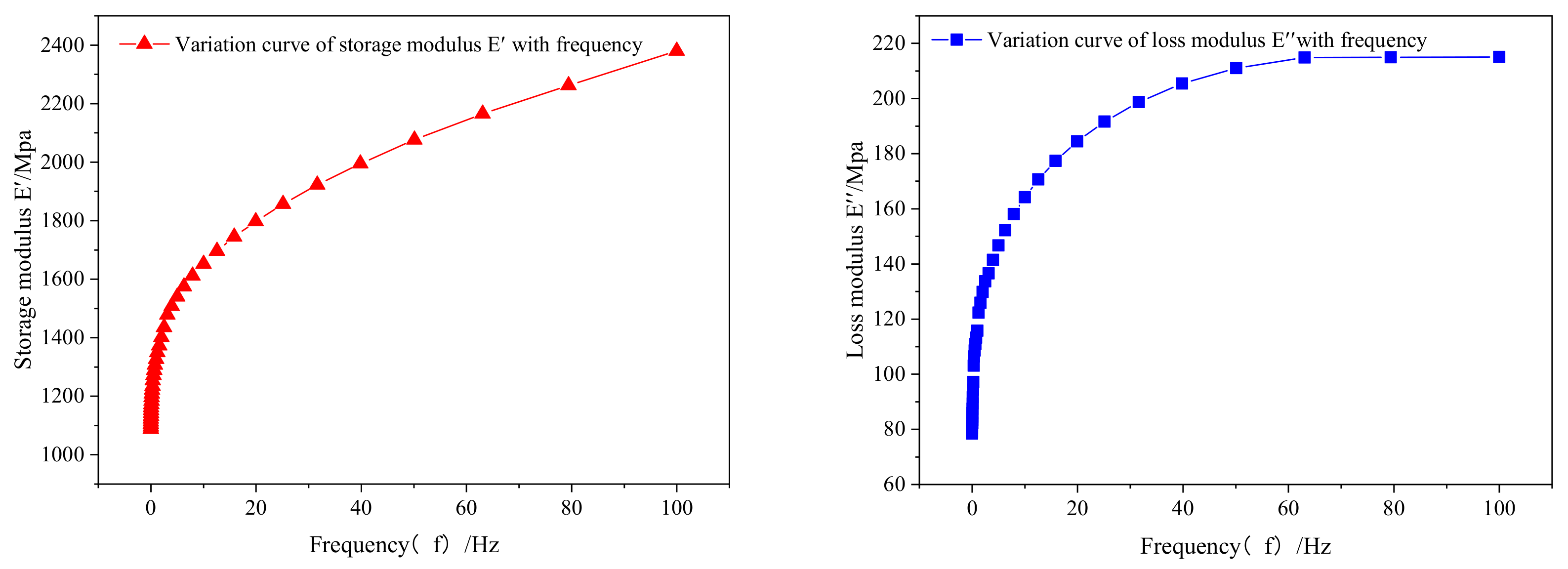
At room temperature, the damping material is tested at a frequency of 0–100 Hz, and the relationship between its storage modulus, loss modulus and loss factor with frequency is obtained. This is shown in Figure 8 and Figure 9.
It can be seen from Figure 8 that at room temperature, the storage modulus E′ and the loss modulus E″ show an increasing trend with the increase of frequency, while the loss factor first increases and then decreases with the increase of frequency. The molecular chain of viscoelastic damping material is long, at high frequency, and does not have enough time to adjust after being excited; the response to stress can only change the distance between molecules with the help of extremely high energy, showing high modulus and low loss factor. As the frequency decreases, the molecular segments realign and the localized strain caused by the stress relaxes, resulting in a decrease in modulus, and the loss factor reaches its maximum value when the frequency is comparable to the molecular relaxation time. When the frequency is lower, the local strain of the molecular chain is relaxed to a greater extent, and the local interaction between the molecular chains prevents the long-range motion of the chain segment, so the storage modulus and loss modulus change greatly at this time, and the loss factor is sharply down; damping performance is reduced.
The characterization of the damping material by DMA shows that the temperature and frequency have a great influence on the performance of the damping material. At the same frequency, the storage modulus decreases with the increase of temperature. When the modulus is located in the glass transition region, the decrease of the modulus is the largest, and the loss factor shows a trend of first increase and then decrease; it reaches the maximum at Tg. At the same temperature, the higher the frequency, the higher the storage modulus; the loss factor first increases and then decreases, and the Tg is on the rise. When using two base fluids to formulate wide temperature range damping materials, the high frequency will affect the fusion of the two peaks, thus affecting the widening of the temperature range.
4.2. Modal Test Analysis
The experimental modal analysis is to collect input and output signals through the data acquisition system, and obtain modal parameters through parameter identification. In this paper, the modal test of the cantilever state of the specimen is mainly carried out by the hammer excitation method, and its frequency response function is measured at several selected points in turn. The excitation and response time-domain signals are transformed into frequency-domain signals through FFT, and the damping ratios of each order are obtained by calculation.
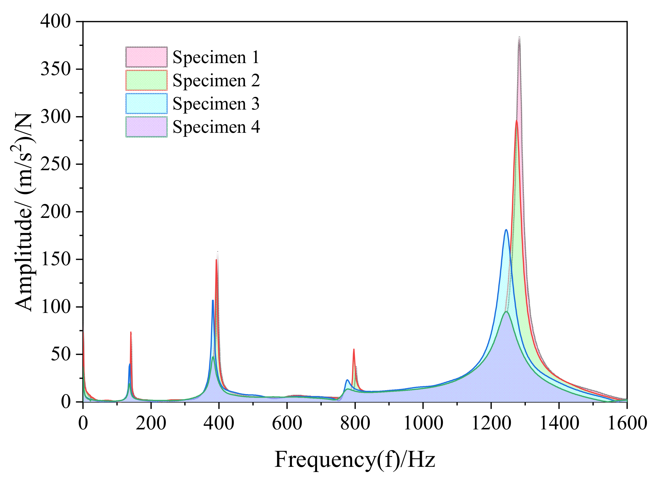
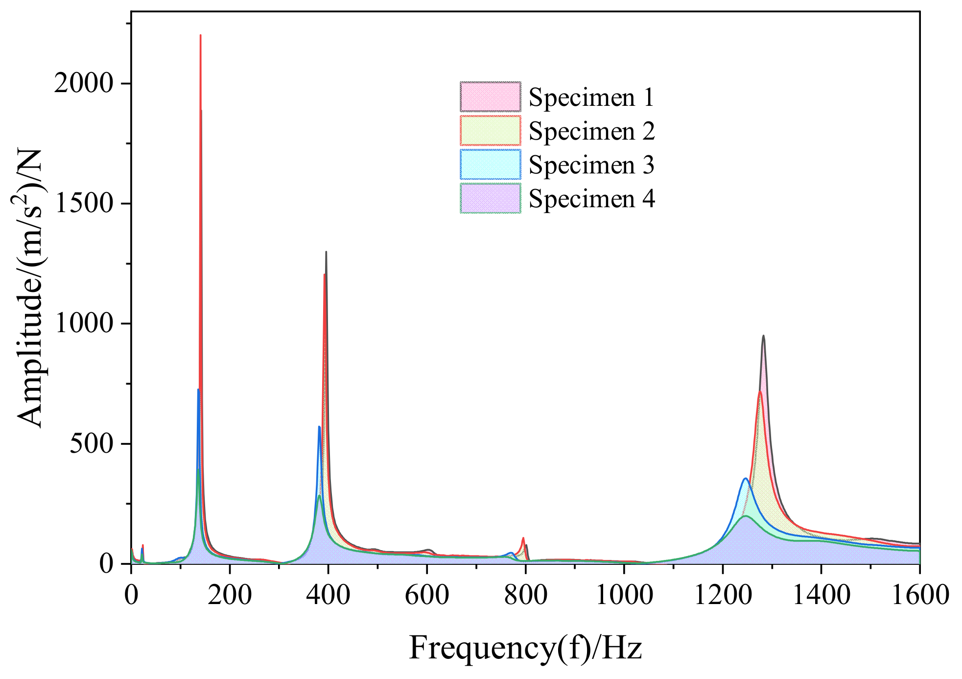
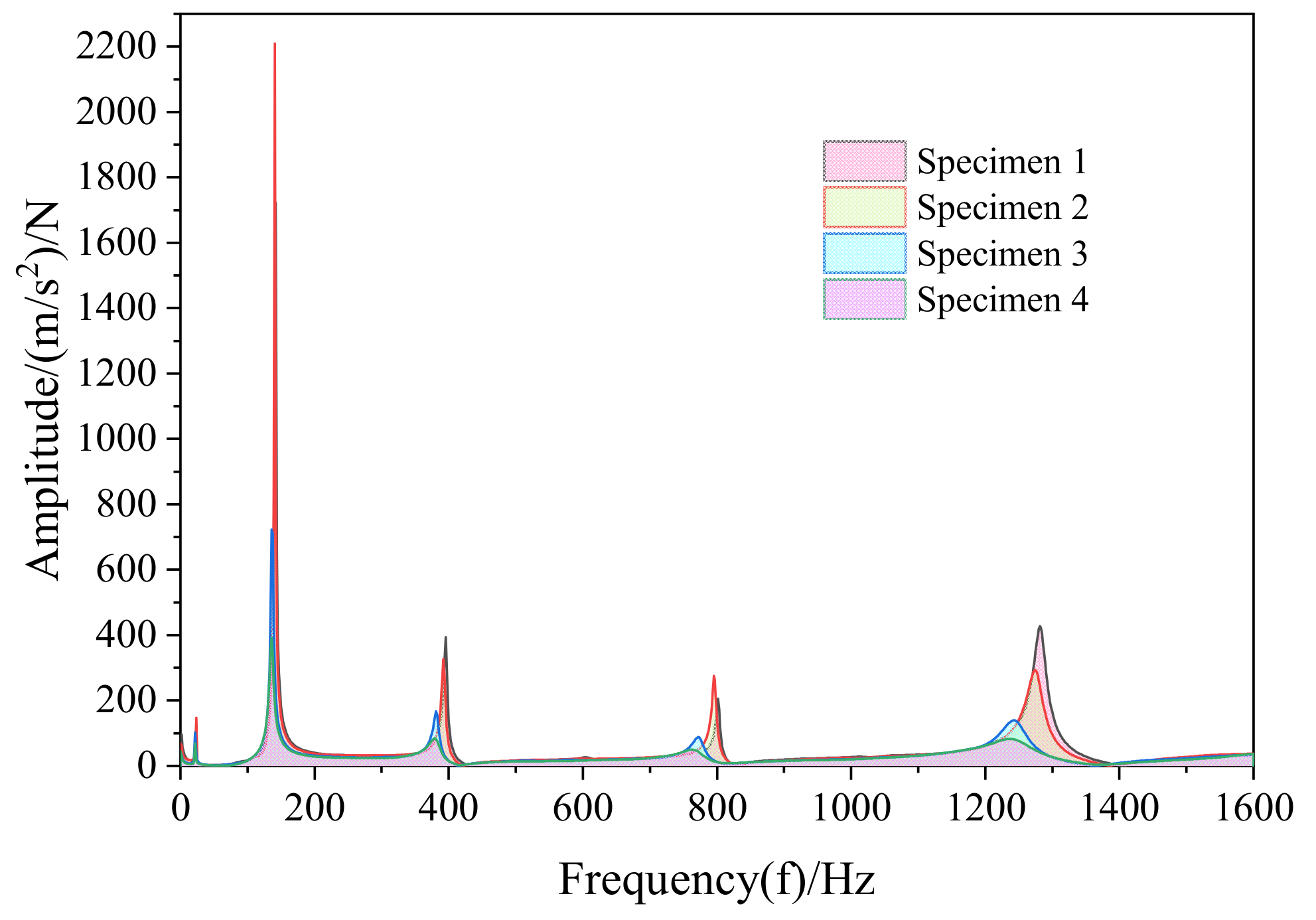
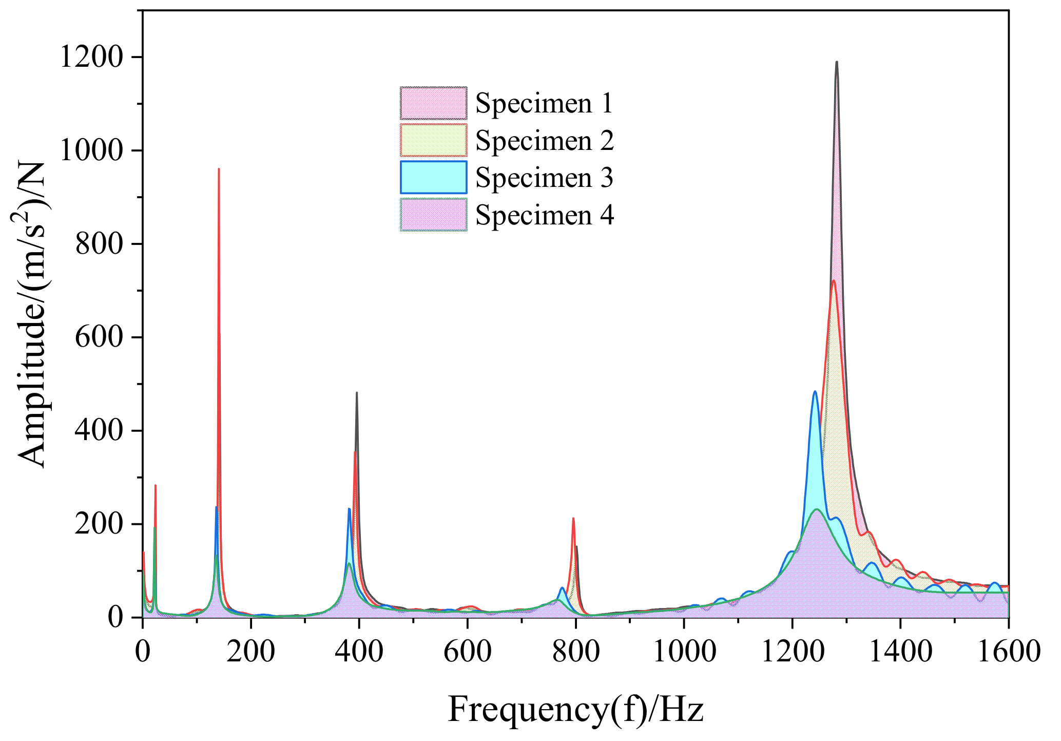
Compare the frequency response function within 0–1600 Hz according to the test results, as shown in Figure 10, Figure 11, Figure 12, Figure 13, Figure 14, Figure 15 and Figure 16.
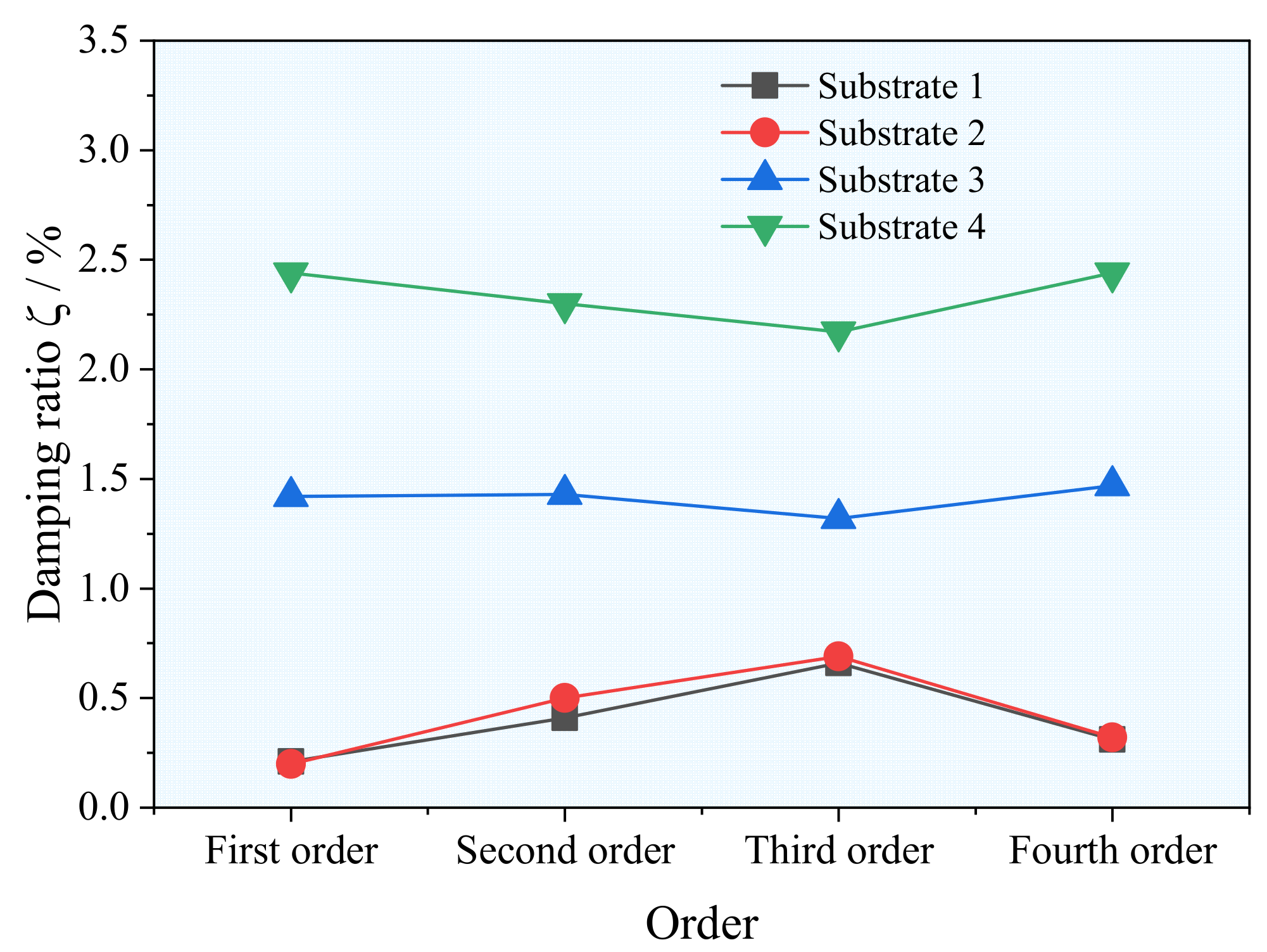
The frequency response function of the four specimens is obtained by modal analysis. From the amplitudes of the four specimens at seven measuring points, it can be seen in Figure 10, Figure 11, Figure 12, Figure 13, Figure 14, Figure 15 and Figure 16 that although specimens 1 and 2 are of the same material, their frequency response characteristics are slightly different due to problems such as machining accuracy and the defects of the material itself; the natural frequency and the amplitude of the frequency response function of the composite structure coated with damping material is smaller than that of the base material. The thicker the damping material, the smaller the amplitude of the frequency response function. The damping ratios of the four specimens’ first four orders are obtained through modal identification and calculation. The data show that the damping material makes a great change in the damping ratio of the composite structure. At the same time, it can be seen in Figure 17 that the damping ratio of the composite structure, whose damping material is twice as thick as that of the base material, is larger, indicating the thickness ratio of damping material to substrate is a key factor affecting the damping performance of composite structures.
Modal identification of the frequency response functions of specimens 3 and 4 are performed, obtaining their first-order natural frequencies and damping ratios, as shown in Table 4. At the same time, the first four-order natural frequency change rate of specimens 3 and 4 are calculated, then compared and analyzed. From the natural frequency change rate in Figure 18, it can be shown that the damping ratio of the composite structure is also nonlinear with the thickness of the damping layer. However, in the first, second, and fourth order, the greater the thickness of the viscoelastic material, the greater the rate of change of the natural frequency of the composite structure. At a specific frequency, the frequency change rate of the composite structure with the damping material to substrate thickness ratio of 1 is larger, and the frequency change rate is 3.34%, indicating that the damping effect is better.
The first four-order mode shapes obtained from the experimental modal analysis are shown in Figure 19. Its mode shapes are all bent along the length direction. Comparing the experimental and finite element analysis results, Figure 19 and Figure 20 show that the modal shapes obtained in the experimental and finite element analysis are identical for the same order. At the same time, it can be seen from the experimental results that the first four-order modes of the four specimens follow the same bending rules, but the frequencies and damping ratios of the four specimens are different.
5. Conclusions
In order to study the damping properties of viscoelastic damping materials, the influence of temperature and frequency on the properties of damping materials is analyzed by DMA based on the molecular structure of materials. The viscoelastic damping material is also coated on the substrate to form a composite structure. The modal identification of the composite structures is carried out by the experimental modal analysis method, explaining the influence of the thickness of the viscoelastic damping material on the composite damping factor from a macroscopic point of view. At the same time, the correctness of the experimental method is verified by finite element calculation. Several concluding comments on viscoelastic damping materials are as follows.
At the same frequency, the storage modulus decreases with the increase of temperature. When the modulus is located in the glass transition region, the reduction range is the largest, and the loss factor shows a trend of first increase and then decrease; it reaches the maximum at Tg. At the same temperature, the higher the frequency, the higher the storage modulus; the loss factor first increases and then decreases, and the Tg tends to increase. In this paper, the viscoelastic damping material is studied at −50 °C~150 °C. A peak value of loss factor is 0.53 at 52.92 °C, indicating that the damping material has the best damping performance at high temperature.
From the research results of the frequency response function and damping ratio of the composite structure, it is shown that in the range of setting the ratio of the thickness of the damping layer to the thickness of the substrate to 1–2 times, the greater the thickness of the damping layer, the smaller the natural frequency of the composite structure, the larger the damping ratio, and the damping material has better damping effect.
Comparing the first four-order natural frequencies of specimens 3 and 4, when the thickness of the damping layer is one times the thickness of the base material, the change rate of the first-order natural frequency is the largest, which is reduced by 4.54%; when the thickness of the damping layer is two times the thickness of the base material, the change rate of the third-order natural frequency is the largest, which is reduced by 5.95%.
In this paper, the damping performance of viscoelastic damping materials is studied from macroscopic and microscopic perspectives. We obtain the effects of temperature and frequency on damping material properties, and explain the effect of damping layer thickness on composite structures. Now, the intelligent damping structure has been proposed by many researchers, but the material itself has not been intelligentized. It is hoped that this research can provide a theoretical basis for the research of intelligent damping materials.
Author Contributions
Conceptualization, J.Y. and F.W.; methodology, F.W.; software, C.H.; validation, F.W.; formal analysis, J.L.; investigation, H.L.; resources, J.L.; data curation, C.H.; writing—original draft preparation, F.W.; writing—revitiew and editing, H.Y. and J.Y.; visualization, F.W.; supervision, H.Y.; funding acquisition, H.Y. and J.Y. All authors have read and agreed to the published version of the manuscript.
Funding
Science and Technology Project of Fujian Province: 2021H0020; Science and Technology Project of Fujian Province: 2020H0018; Supported by Fund of Xiamen Key Laboratory of Marine Corrosion and Smart Protective Materials.
Institutional Review Board Statement
Not applicable.
Informed Consent Statement
Informed consent was obtained from all subjects involved in the study.
Data Availability Statement
All data used to support the findings of this study are included within the article.
Conflicts of Interest
The authors declare that they have no conflict of interest regarding the publication of this paper.
References
- Yingdong, G.; Chunlong, S.; Haiyan, L.; Shizhen, Z.; Hong, W.; Wenge, W. Research Progress in Organic Polymer Damping Coatings. Paint. Coat. Ind. 2011, 9, 73–76. [Google Scholar]
- Yunfeng, Z. Properties and Application of Advanced Viscoelastic Damping Materials. Aerosp. Mater. Technol. 2009, 39, 1–6. [Google Scholar]
- Gibson, R.F. A review of recent research on mechanics of multifunctional composite materials and structures. Compos. Sci. Technol. 2014, 105, 51–65. [Google Scholar]
- Zhiyuan, W.; Liushuan, Y. Progress of High Damping Foam Metal Metrix Composite. Dev. Appl. Mater. 2004, 19, 38. [Google Scholar]
- Huang, Z.-C.; Qin, Z.-Y.; Chu, F.-L. A review about vibration problems of thin-walled structures with viscoelastic damping layer. J. Vib. Shock. 2014, 33, 105–113. [Google Scholar]
- Fang, Q.-F.; Zhu, Z.-G.; Ge, T.-S. Characterization and Mechanism of High Damping Materials. Physics 2000, 9, 541–545. [Google Scholar]
- Kang, Z.; Zhang, X.P.; Jiang, S.G.; Cheng, G. On topology optimization of damping layer in shell structures under harmonic excitations. Struct. Multidiscip. Optim. 2012, 46, 51–67. [Google Scholar]
- Kim, S.Y.; Chris, K.M.; Kim, I.Y. Optimal damping layout in a shell structure using topology optimization. J. Sound Vib. 2013, 332, 2873–2883. [Google Scholar]
- Yamamoto, T.; Yamada, T.; Izui, K.S.; Nishiwaki, S. Topology optimization of free-layer damping material on a thin panel for maximizing modal loss factors expressed by only real eigenvalues. J. Sound Vib. 2015, 358, 84–96. [Google Scholar]
- Takezawa, A.; Daifuku, M.; Nakano, Y.; Nakagawa, K.; Yamamoto, T.; Katimura, M. Topology optimization of damping material for reducing resonance response based on complex dynamic compliance. J. Sound Vib. 2015, 358, 84–96. [Google Scholar]
- EI-Sabbagh, A.; Baz, A. Topology optimization of unconstrained damping treatments for plates. Eng. Optim. 2014, 46, 1153–1168. [Google Scholar]
- Zhang, X.P.; Kang, Z. Vibration suppression using integrated topology optimization of host structures and damping layers. J. Vib. Control 2016, 22, 66–76. [Google Scholar]
- Yun, K.S.; Youn, S.K. Topology optimization of viscoelastic damping layers for attenuating transient response of shell structures. Finite Elem. Anal. Des. 2018, 141, 154–165. [Google Scholar]
- Yi, Y.M.; Park, S.H.; Youn, S.-K. Asymptotic homogenization of viscoelastic composites with periodic microstructures. Int. J. Solids Struct. 1998, 35, 2039–2055. [Google Scholar]
- Andreassen, E.; Jensen, J.S. Topology optimization of periodic microstructures for enhanced dynamic properties of viscoelastic composite materials. Struct. Multidiscip. Optim. 2014, 49, 695–705. [Google Scholar]
- Chen, W.; Liu, S. Topology optimization of microstructures of viscoelastic damping materials for a prescribed shear modulus. Struct. Multidiscip. Optim. 2014, 50, 287–296. [Google Scholar]
- Li, K. Research on Vibration Reduction Efficiency of Composite High Damping Materials. Space Electron. Technol. 2004, 1, 42–54. [Google Scholar]
- Priyankar, D.; Ray, M.C. Smart damping of large amplitude vibrations of variable thickness laminated composite shells. Thin-Walled Struct. 2018, 127, 710–727. [Google Scholar]
- Sahoo, S.R.; Ray, M.C. Active damping of geometrically nonlinear vibrations of smart composite plates using elliptical SCLD treatment with fractional derivative viscoelastic layer. Eur. J. Mech. A Solids 2019, 78, 103823. [Google Scholar]
- Gupta, A.; Reddy, R.S.; Panda, S.; Kumar, N. Damping treatment of beam with unconstrained/constrained 1-3 smart viscoelastic composite layer. Eur. J. Mech. A Solids 2019, 26, 956–962. [Google Scholar]
- Fu, W.; Wang, C.; Chen, J.; Lai, X.; Li, H. Operational modal analysis of three-dimensional structure based on Laplacian Eigenmaps. Comput. Integr. Manuf. Syst. 2020, 2020, 6348372. [Google Scholar]
- El-Labban, M.; Abdelaziz, M.Y.; Elkhatib, A. Prediction of Mechanical Properties of Nano-Composites Using Vibration Modal Analysis: Application to Aluminum Piston Alloys. Mater. Perform. Charact. 2013, 2, 454–467. [Google Scholar] [CrossRef]
- Chang, K.-C.; Kim, C.-W. Modal-parameter identifification and vibration-based damage detection of a damaged steel truss bridge. Eng. Struct. 2016, 122, 156–173. [Google Scholar] [CrossRef]
- Guan, C.; Zhang, H. Experimental and Theoretical Modal Analysis of Full-Sized Wood Composite Panels Supported on Four Nodes. Materials 2017, 10, 683. [Google Scholar] [CrossRef] [Green Version]
- Mostafa, Y.; Elkhatib, A.; Nassef, M.G.A. Rolling element bearings absolute life prediction using modal analysis. J. Mech. Sci. Technol. 2018, 32, 91–99. [Google Scholar] [CrossRef]
- Qiuhai, L.; Debao, L. Analysis of Experiments in Engineering Vibration; Tsinghua University Press: Beijing, China, 2015. [Google Scholar]
- Fu, Z.; Hua, H. Modal Analysis Theory and Applications; Shanghai Jiaotong University Press: Shanghai, China, 2000. [Google Scholar]
- Zhang, Z. Study on Viscoelastic Damping Material and Constrained Damping Structure Applied in Qingdao Subway Vibration and Noise Reduction; Qingdao Technological University: Qingdao, China, 2014; p. 18. [Google Scholar]
Figure 1.
The form of viscoelastic damping laid on the substrate structure. (a) Free damping structure; (b) passive restraint damping structure; (c) active constraint damping structure; and (d) intelligent damping structure.
Figure 1.
The form of viscoelastic damping laid on the substrate structure. (a) Free damping structure; (b) passive restraint damping structure; (c) active constraint damping structure; and (d) intelligent damping structure.

Figure 2.
Specimen. ①is the specimen 1; ②is the specimen 2; ③is the specimen 3; and ④is the specimen 4.
Figure 2.
Specimen. ①is the specimen 1; ②is the specimen 2; ③is the specimen 3; and ④is the specimen 4.

Figure 3.
METTLER TOLEDO Dynamic Mechanical Analysis.

Figure 4.
Device connection diagram.

Figure 5.
Test scene device connection diagram.

Figure 6.
Relationship between storage modulus, loss factor, and temperature of viscoelastic damping material at different frequencies.
Figure 6.
Relationship between storage modulus, loss factor, and temperature of viscoelastic damping material at different frequencies.

Figure 7.
Corresponding values of tanδ and Tg at 1 Hz, 10 Hz, 50 Hz, and 136 Hz.

Figure 8.
Variation curve of storage modulus and loss modulus with frequency.

Figure 9.
Variation curve of loss factor with frequency.

Figure 10.
Frequency response function curve of the first measuring point.

Figure 11.
Frequency response function curve of the second measuring point.

Figure 12.
The frequency response function curve of the third measuring point.

Figure 13.
The frequency response function curve of the fourth measuring point.

Figure 14.
Frequency response function curve of the fifth measurement point.

Figure 15.
Frequency response function curve of the sixth measurement point.

Figure 16.
Curve of frequency response function of the seventh measuring point.

Figure 17.
Damping ratio of base material and composite damping structure.

Figure 18.
Natural frequency change rate.

Figure 19.
The first four-order experimental modal diagram. (a) First-order mode shape; (b) second-order mode shape; (c) third-order mode shape; and (d) fourth-order mode shape.
Figure 19.
The first four-order experimental modal diagram. (a) First-order mode shape; (b) second-order mode shape; (c) third-order mode shape; and (d) fourth-order mode shape.

Figure 20.
The first four-order simulation modal diagram. (a) First-order mode shape; (b) second-order mode shape; (c) third-order mode shape; and (d) fourth-order mode shape.
Figure 20.
The first four-order simulation modal diagram. (a) First-order mode shape; (b) second-order mode shape; (c) third-order mode shape; and (d) fourth-order mode shape.


Table 1.
DMA Sample dimension.
| NO. | Name | Length [mm] | Width [mm] | Thickness [mm] |
|---|---|---|---|---|
| 1 | Sample 1 | 20 | 1.8 | 0.9 |
| 2 | Sample 2 | 20 | 1.85 | 0.8 |
| 3 | Sample 3 | 20 | 4.4 | 0.72 |
| 4 | Sample 4 | 20 | 4.5 | 0.78 |
| 5 | Sample 5 | 20 | 5 | 0.6 |
Table 2.
Specimen size parameter.
| NO. | Name | Length [mm] | Thickness [mm] | Width [mm] |
|---|---|---|---|---|
| 1 | Specimen 1 | 300 | 3 | 20 |
| 2 | Specimen 2 | 300 | 3 | 20 |
| 3 | Specimen 3 | 300 | 6 | 20 |
| 4 | Specimen 4 | 300 | 9 | 20 |
Table 3.
Specifications and models of equipment used in modal experiments.
| NO. | Name | Model Specifications |
|---|---|---|
| 1 | LMS Test. Lab Modal Testing Advanced | TL-STR.29.2 |
| 2 | ICP® accel., 100 mV/g, 0.5 Hz to 3 kHz, 10–32 side conn | 333B30 |
| 3 | PCB General purpose cable, 30-ft, 10–32 plug to BNC plug | 002C30 |
| 4 | Modally Tuned® Impulse Hammer w/force sensor and tips, 0 to 5 klbf, 1 mV/lbf (0.23 mV/N) | 086D05 |
| 5 | Low-noise, blue, coaxial, Teflon cable, 20-ft, BNC plug to BNC plug | 003D20 |
| 6 | Handheld shaker, 1 g at 159.2 Hz | 394C06 |
Table 4.
Natural frequencies and damping ratios of specimens 3 and 4.
| Structural Type | Base Layer [mm] | Damping Layer [mm] | First Natural Frequency [Hz] | Damping Ratio [%] |
|---|---|---|---|---|
| Steel | 3 | / | 23.27 | 0.21 |
| Steel | 3 | / | 23.16 | 0.20 |
| Steel-Damping | 3 | 3 | 22.22 | 1.42 |
| Steel-Damping | 3 | 6 | 21.78 | 2.44 |
Publisher’s Note: MDPI stays neutral with regard to jurisdictional claims in published maps and institutional affiliations. |
© 2022 by the authors. Licensee MDPI, Basel, Switzerland. This article is an open access article distributed under the terms and conditions of the Creative Commons Attribution (CC BY) license (https://creativecommons.org/licenses/by/4.0/).
Share and Cite
MDPI and ACS Style
Wang, F.; Liao, J.; Huang, C.; Yu, H.; Yan, J.; Li, H. Study on the Damping Dynamics Characteristics of a Viscoelastic Damping Material. Processes 2022, 10, 635. https://doi.org/10.3390/pr10040635
AMA Style
Wang F, Liao J, Huang C, Yu H, Yan J, Li H. Study on the Damping Dynamics Characteristics of a Viscoelastic Damping Material. Processes. 2022; 10(4):635. https://doi.org/10.3390/pr10040635
Chicago/Turabian StyleWang, Fei, Jianbin Liao, Chaoming Huang, Hongliang Yu, Jin Yan, and Hanlin Li. 2022. "Study on the Damping Dynamics Characteristics of a Viscoelastic Damping Material" Processes 10, no. 4: 635. https://doi.org/10.3390/pr10040635
Note that from the first issue of 2016, this journal uses article numbers instead of page numbers. See further details here.