
Heat Transfer Performance of Plate Fin and Pin Fin Heat Sinks Using Al2O3/H2O Nanofluid in Electronic Cooling


1
Department of Mechanical Engineering, Akdeniz University, Antalya 07058, Turkey
2
Department of Material Science and Engineering, Akdeniz University, Antalya 07058, Turkey
*
Author to whom correspondence should be addressed.
Processes 2022, 10(8), 1644; https://doi.org/10.3390/pr10081644
Submission received: 7 July 2022
/
Revised: 8 August 2022
/
Accepted: 16 August 2022
/
Published: 18 August 2022
(This article belongs to the Special Issue Recent Advances in Cooling of Electronic Components)
Abstract
:The thermal management of electronic devices has become a major problem in recent years. Therefore, there is a growing need for research on many new materials and innovative fluids due to the developing technology and increasing cooling need in electronic systems. In this paper, heat transfer from a plate fin and pin fin type heat sinks that were placed in a water block that are used in electronic systems was investigated. A base fluid (pure water) and 0.1% mass concentration Al2O3-H2O nanofluid were used as cooling fluids. The experiments were carried out for volumetric flow rates varying between 100 and 800 mL/min and heat flux values of 454.54 W/m2 and 1818.18 W/m2. The results demonstrated that the Al2O3-H2O nanofluid on the empty surface provided a maximum improvement of 10.5% in heat transfer compared to the base fluid. In the use of plate finned heat sink, the maximum amount of improvement in heat transfer compared to the empty surface was obtained approximately 64.25% for the base fluid and 82.8% for the nanofluid. A similar comparison was made for the pin-fin heat sink, a maximum thermal improvement of 56.4% in the base fluid and 70.27% in the use of nanofluid was determined.
1. Introduction
There are many types of damage in electronic systems that cause performance degradation or loss of parts because of failure. In addition to damage types such as humidity, vibration, and incorrect installation, the most common type of damage is overheating. Every electronic element in the device or machine needs electrical energy to work. After all electronic elements fulfill their functions, they convert the excess energy that is formed in their structures into heat energy. This energy accumulates in their structure and causes increase in the temperature of the electronic elements. When this temperature increase exceeds a certain limit, it causes the performance of the electronic element to decrease and becomes unusable by deteriorating. To overcome this problem, studies on the development of more effective cooling systems by many researchers are increasing day by day. While the performance of electronic systems increases with the developing technology, their dimensions decrease inversely. Accordingly, there is an increase in the amount of heat that is produced per unit area. Considering the increased heat generation in the electronic element, the cooling systems that are currently used are in some cases extremely inadequate. The most effective way to solve this problem is to develop the cooling systems that are used in accordance with the current technology. In this context, recent studies have been reviewed and many studies that are aimed at increasing the performance of electronic cooling systems are summarized below.
Choi and Eastman. [1] demonstrated the applicability of the nanofluids concept theoretically for the first time. They stated that materials with high thermal conductivity in nature (metal, ceramics, carbon nanotubes, etc.) can be used by adding in certain concentrations to the base fluid to increase the performance. By increasing the thermal conductivity of nanofluids with copper nanophase materials, they made predictions about heat transfer enhancement as a function of the thermal conductivity. It should also be noted that the term nanofluid was first introduced to the literature by Choi and Eastman. After the publications of Choi and Eastman, many researchers have carried out many studies on nanofluids with different parameters in different fields. Nazari et al. [2] investigated the effect of different nanofluids on heat transfer in the CPU (central process unit) cooling system. In the study, nanofluids with volumetric concentrations of 0.1%, 0.25%, and 0.5% alumina-water and 0.1% and 0.25% CNT (carbon nanotubes) were used as cooling fluids. The obtained results compared with water and ethylene glycol. Rafati et al. [3] studied the effect of different nanofluids using a cooling kit used in computers. The fluids were prepared using three different (SiO2, TiO2, and Al2O3) nanoparticles. A water-ethylene glycol mixture was preferred as the base fluid. In the heat transfer results that were obtained, they determined that the nanofluids reduced the processor temperature compared to pure water. The highest temperature drops of 5.5 °C in the processor temperature were obtained with the use of alumina nanofluid at a flow rate of 1 L/min and a concentration of 1% by volume. Sarafraz et al. [4] experimentally investigated the thermal performance of a cooling block working with gallium, CuO-water nanofluid, and water. They used 0.1%, 0.2%, and 0.3% CuO-water nanofluid by mass. According to the results that were obtained, higher thermal performance was obtained with the use of gallium compared to nanofluid, pure water, and fan cooling. Although there was a significant increase in the pressure drop and pumping power, by using gallium, the best thermal performance was obtained. The effect of nanofluids on the microchannel heat sink performance of computer cooling systems was experimentally investigated by Alfaryjat et al. [5]. Nanofluids that were produced with CeO2, Al2O3, and ZrO3 nanoparticles and a mixture of 20% ethylene glycol-80% pure water were used as a cooling fluid. While the concentrations of the used nanofluids were changed between 0.5% and 2%, the mass flow rate was changed in the range of 0.028–0.084 kg/s. Selvakumar and Suresh [6] experimentally investigated the effects on heat transfer CuO/water nanofluids with a volume concentration of 0.1% and 0.2% in a copper water block. It was seen that 0.2% CuO/water nanofluid lowered the surface temperature by a maximum of 1.15 °C compared to pure water. The effect of the particle volume concentration on the convective heat transfer coefficient and pressure drop was also presented in detail. Korpys et al. [7] used distilled water and copper oxide nanofluids with different volume fractions (0.0086 and 0.0225) to cool the PC processor on which a commercial finned heat sink was placed. The experimental results were compared to validate the numerical model the ANSYS Fluent 13 was employed to generate a CFD heat transfer simulation. According to the results that were obtained, the maximum decrease in the CPU temperature was 0.5 K, with the use of 0.0225% CuO-water nanofluid by volume. As a result, they stated that the use of water in CPU cooling was sufficient. Another experimental study examining the use of nanofluids in the cooling of microprocessors was conducted by Nguyen et al. [8]. A water block with needle-finned plates was used as a heat sink. Volume concentrations of 0.95%, 2.2%, and 4.5% Al2O3-water nanofluid was chosen as the cooling fluid. As a result of the study, it was seen that the use of nanofluids to cool a heated element is more advantageous than pure water. It was stated that the convection heat transfer coefficient increased with both the mass flow rate and particle volumetric concentration. A 23% heat transfer improvement was observed in Al2O3-water nanofluid at 4.5% vol. concentration compared to pure water. Turgut and Elbasan [9] experimentally investigated the cooling performance of nanofluid with a particle concentration of 6.33 volumetric percent and diluted to 1 volumetric percent with water. The results showed that nanofluids with low volume concentration of alumina particles decreased the maximum temperature of the system by approximately 2.7 °C, compared to water. Qi et al. [10] discussed the effects of the Al2O3-water and TiO2-water nanofluids with different mass concentrations on thermal performance and flow characteristics in a CPU heat sink. The experiments were made for Reynolds numbers that varied from 146 to 812. In the obtained results, it was seen that for the best heat transfer performance did not occur at the highest mass concentration. They determined that the Nusselt number first increased and then decreased with mass concentration. They stated that the best results in Al2O3-water and TiO2-water nanofluids were obtained at concentrations of 1% and 0.4% by mass, respectively. At the same time, they determined that the CPU temperatures with Al2O3-water and TiO2-water nanofluids were improved by 23.2% and 14.9%, respectively, when compared to water. To reduce the interface temperature of the water block, Shah et al. [11] prepared a TiO2-water nanofluid with a volume fraction of 0.1% by dispersing nanoparticles in pure water. Different volumetric flow rates (1, 1.25, and 1.5 L/min) were studied in the experiments. They reduced the interface temperature of the water block by about 6.4 °C compared to pure water. The obtained results showed that the maximum energy efficiency reached up to 77.56% with the use of nanofluids. Arya et al. [12] experimentally presented the thermal performance of a convective cooling loop for ZnO-water nanofluids at mass concentrations that varied from 0.1% to 0.4%. The results showed that ZnO/water nanofluid was a promising coolant for cooling microelectronic devices and chipsets, although the pressure drop was slightly higher than that of pure water. In addition, it was stated that the maximum heat transfer coefficient was provided at a mass concentration of 0.3% which was an optimum value of nanofluid. The existence of nanoparticles enhanced the friction factor and pressure drop, however, it was concluded that it was not very important when compared with the base fluid. Ho and Chen [13] investigated the thermal performance of the Al2O3-water nanofluid at mass concentrations that varied from 0.5% to 10% in a mini-channel heat sink under forced convection conditions. Compared to pure water, it was stated that the average heat transfer coefficient in the use of 10% Al2O3-water nanofluid by mass increased by 72% and 35%, respectively, according to the bulk and inlet temperature differences. They noticed that taking into account the pumping power penalty, the merit parameters of using the Al2O3-water nanofluid at a constant flow rate in the heat sink seem to be augmenting greater than unity with the particle fraction at 6 wt.%. Numerical investigation of the thermal characteristics of a hybrid nanofluid in micro-pin fin heat sink for electronic cooling was modelled by Sukhor et al. [14]. An Al2O3-Cu/water hybrid nanofluid with a volume concentration in the range of 0.1% to 0.5% was used for the working fluid in a micro heat sink. The obtained numerical results were compared with experimental results from the literature to validate the accuracy. Hasan [15], numerically investigated the heat transfer from three types of micro-pin heat sinks with square, triangular, and circular geometries and finless micro-channel heat sinks. Pure water, diamond-water, and Al2O3-water nanofluids were used as coolants. The volumetric concentrations of the nanofluids that were used varied between 1% and 4%. To compare the hydrodynamic and the thermal characteristics of different fin geometries and cooling fluids, the calculations were made under the same value of Reynolds number and constant wall temperature thermal boundary condition. Sajid et al. [16] experimentally investigated the effects of TiO2 nanofluid on heat transfer and hydrodynamic characteristics in wavy channel heat sinks having three different channel configurations. The obtained results from the TiO2-water nanofluid with volumetric concentrations of 0.006%, 0.008%, 0.01%, and 0.012% were compared with that of pure water. It was observed that nanofluids provided better heat transfer than pure water in all heat sink types. In addition, it was stated that the thermal performance of the TiO2-water nanofluid decreased with the increase of the heater power. In the heat sink where the fin wavelength is 5 mm and the fin amplitude is 0.5 mm, for nanofluid with 0.012 % volume, the minimum surface temperature was determined as 33.85°C and the maximum improvement amount in the Nusselt number was determined as 40.57%. In addition, Sajid et al. [17] investigated the thermal and exergetic performance of corrugated mini-channel heat sinks that were prepared in different shapes and sizes with MgO-water nanofluid that was prepared at different volumetric concentrations. They stated that the use of nanofluids with corrugated mini-channels reduces the wall temperature more than water. Miry et al. [18], experimentally conducted thermal and hydrodynamic performances of a miniature tangential heat sink by using Al2O3-H2O and TiO2-H2O (volume concentrations of 0.5%, 1%, 1.5%, and 2%) nanofluids. The obtained results showed an enhancement in the convective heat transfer by using nanofluid instead of pure water. In addition, it is concluded that the increase in pumping power can be considered negligible when compared with the increase in the thermal performance and decrease in the thermal resistance. Sehgal et al. [19] presented an experimental study of the effect of inlet and exit conditions being effective due to different flow arrangements on the thermal performance of a copper micro-channel heat sink. There were three different flow arrangements that were studied as U type, S type, and P type. The Reynolds number varied from 224 to 1121. The Nusselt number and pressure drop were determined based on the temperature difference and pressure drop across the inlet and outlet sections for various test combinations. Sarbazi and Hormozi [20] experimentally investigated the optimization of the thermal and hydraulic performances of various nanofluids in a rectangular miniature channel in which different types of longitudinal fins were placed. The highest thermal-hydraulic performance in the miniature channel was obtained in the use of quadrant-2, rectangular, quadrant-1, and semicircular finned silicon oxide/water nanofluids with 1.27, 1.26, 1.16, and 1.11, respectively. The effects of copper-water nanofluid and pin channel on the performance of the plate heat exchanger were experimentally investigated by Alabadi and Hormozi [21]. From the results, it was determined that the pin channel improved the thermal-hydraulic performance of the plate heat exchanger by approximately 38% compared to the straight channel. A 1.65 increase on the average performance was observed with the use of nanofluids and pin channel simultaneously inside the plate-fin heat exchanger. The effect of the Al2O3-water nanofluid use with the miniature heat sinks of plate fins and plate-pin fins with different shapes (triangular, trapezoidal, and sinusoidal) on the thermal and hydraulic performance was investigated by Aliabadi et al. [22]. The experiments were made between 100 and 900 Reynolds numbers. The temperature distribution and velocity vectors were also investigated numerically by the CFD approach. According to the results, it was seen that the thermal performance of the use of plate-pin fins in the corrugated miniature heat sink were better than that of plate fins. Holes and winglets on chevron plate-fins were used to enhance the performance of a plate-fin heat exchanger by Aliabadi and Mortazavi [23]. An Al2O3-water nanofluid was used as a refrigerant. From the results, it was seen that the Nusselt number increased with the simultaneous use of chevron plate fins and nanofluid. Abdollahi et al. [24], thermal and hydraulic properties of nanofluid flow in microchannels with longitudinal inner fins were numerically investigated under laminar flow conditions. A total of four different nanofluids, namely SiO2-water, Al2O3-water, CuO-water, and ZnO-water, were prepared in 1–2% volumetric concentration range. It was seen that the SiO2-water nanofluid had the highest heat transfer performance among all the nanofluids. To determine the best hydrothermal performance, the use of hybrid nanofluids with different particle sizes and properties in the mini-channel heat sink was experimentally investigated by Kumar and Sarkar [25]. Al2O3-MWCNT-water hybrid nanofluid at 0.01% volume concentration with various nanoparticle mixing ratios (5:0, 4:1, 3:2, 2:3, 1:4, and 0:5) was used as the refrigerant. The convection heat transfer coefficient, Nusselt number, pressure drop, and friction factor increased with the increase of MWCNT concentration in the fluid. Compared to pure water, the maximum increase in the convection heat transfer coefficient was obtained with the use of MWCNT (5:0) nanofluid with a ratio of 44.02%. The simultaneous optimization of geometric and nanofluid parameters using four different nanofluids (Al2O3-water, Cu-water, SiO2-water, and CNT-water) in a rectangular microchannel heat sink was performed by Fazeli et al. [26]. From the results, better thermal performance was obtained with the CNT nanofluid compared to other nanofluids. In addition, it was determined that the thermal performance increased with increasing the nanoparticle concentration and decreasing the nanoparticle diameter. The effectiveness of using Al2O3-water+EG nanofluid of four different cross-section pin fin shapes in a heat sink was investigated by Khetib et al. [27]. According to the results that were obtained, it was determined that the total entropy production decreased with the fluid velocity, thus improving the heat transfer. In the use of circular shaped fins, minimum thermal entropy production, and maximum heat transfer were obtained. The effect of nanofluid usage on heat transfer in mini-channels that were made of square-section pin fins that were prepared by Ali and Arshad [28,29] in different arrays and angles was investigated. The use of nanofluids in small diameter pipes were investigated [30,31] and it was observed that there was a decrease in the surface temperatures compared to the base fluid. The heat transfer analysis of needle-finned surfaces of different shapes and sizes in the water block was investigated with different nanofluids [32,33].
Ambreen and Kim [34,35] numerically investigated the use of nanofluids with mini- and micro-channels under laminar forced convection conditions. The water-based Al2O3 and TiO2 nanofluids that were prepared at different mass and volumetric concentrations were used as cooling fluids. In the first study, it was observed that the best hydrothermal results were obtained in the discrete phase model (DPM) for all nanofluid volume concentrations. In the second study, it was determined that the heat transfer and friction factor were inversely related to the particle diameter for constant nanofluid compositions and flow conditions. The effect of heat transfer using micro-pin finned heat sink nanofluids was numerically investigated in various studies [35,36,37,38,39]. Different pin fin geometries and different fin placements were investigated using different nanofluids. In the obtained results, it was determined that the nanofluids performed better in certain fin cross-sections. The heat transfer and pressure drop properties of water-based multi-walled carbon nanotube (MWCNT) nanofluid and multi-walled carbon nanotubes/graphene nanoplatelet (MWCNT/GNP) nanofluids were numerically investigated by Ambreen et al. [40]. The analysis was performed in the range of 0.075% to 0.25% by weight of the particle concentration and the Reynolds number in the range of 200–470. According to the results, it was determined that the Lagrange–Eulerian approach provided the most accurate convective heat transfer values for all the nanofluid combinations and operating conditions. Numerical investigation of the use of aqueous-based nano-encapsulated phase change material (PCM) at different fin angles (0 ≤ ζ ≤ 270) in a heat exchanger with different wing-like fins was carried out by Shehzad et al. [41]. According to the results, it was determined that the vertical alignment of the blades increased the thermal performance compared to the horizontal alignment of the blades. The thermal efficiency of the aqueous-based Ti3C2Tx MXene nanofluid in a pin-fin heat sink was investigated experimentally and numerically by Ambreen et al. [42]. From the results, it was seen that there was a significant increase in the average Nusselt number despite the small increase in pumping power with the use of Ti3C2Tx Mxene nanofluid.
From the literature review above, the effect of using different surface types together with nanofluids on heat transfer in electronic systems and CPU cooling systems were investigated in many studies. It is noteworthy that there were very few studies comparing the Thermo-hydraulic performance of plate-fin and pin-fin heat sinks used commercially in electronic cooling systems and CPU cooling systems with the use of nanofluids. Most of the studies that were mentioned were numerical studies. In the experimental study, the effect of the using a plate fin and pin fin heat sink in a water block on thermohydraulic performance was examined in detail, in order to eliminate this deficiency that was seen in the literature. As the cooling fluid, an Al2O3-H2O nanofluid was used at a concentration of 0.1% by mass, prepared using spherical Al2O3 nanoparticles that were smaller than 20 nm. The obtained results were compared with pure water and empty surface. In this context, as a result of experiments with different heat fluxes and different volumetric flow rates with both fluids, comparisons were made in various parameters, and it was determined which surface geometry was more effective in electronic cooling.
2. Materials and Methods
2.1. Experimental Set-Up
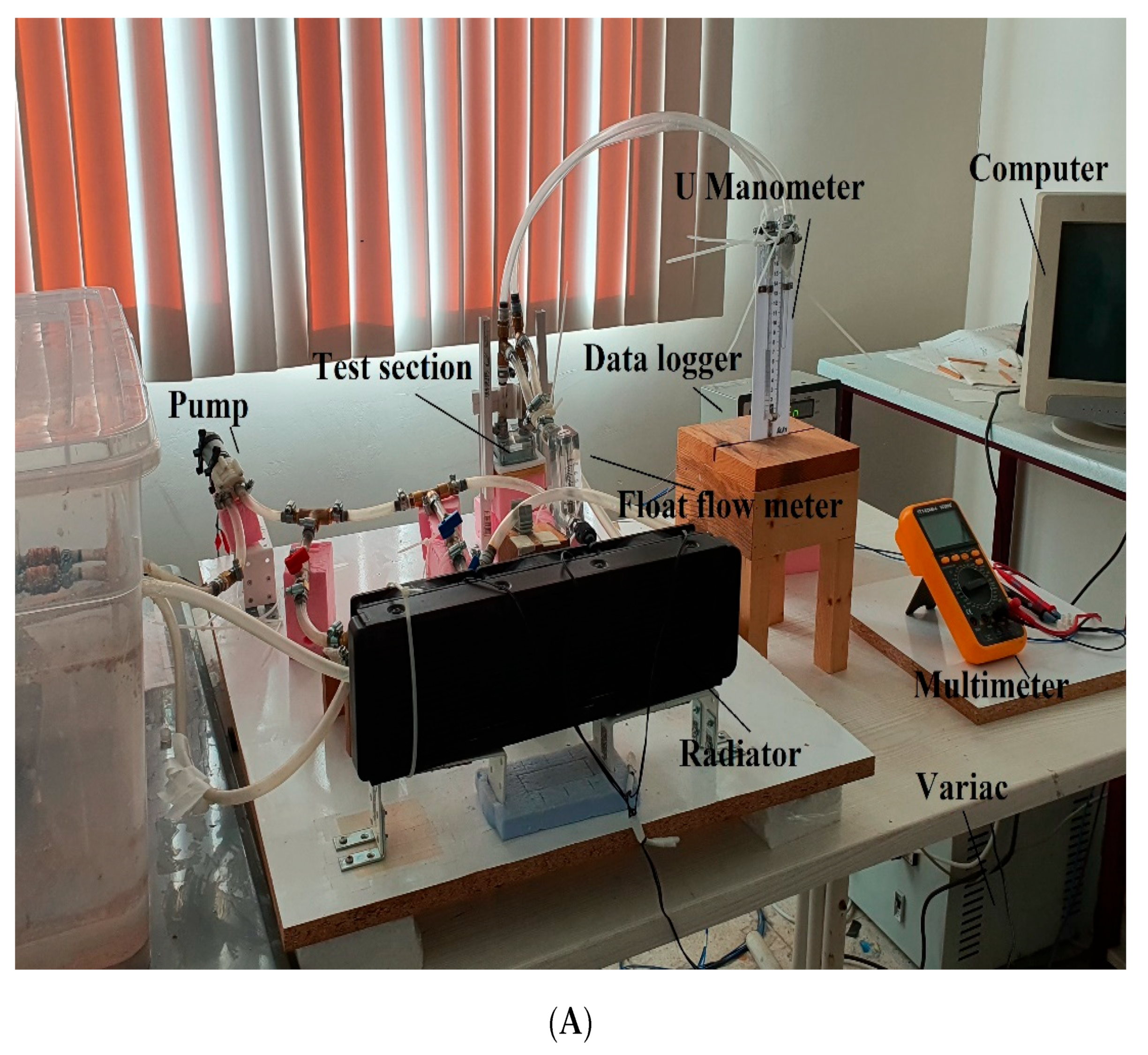
The appearance and schematic drawing of the experimental setup in which the effect of heat sinks with different surface areas that were used in electronic cooling systems on heat transfer was examined and given in Figure 1.
The experimental setup consisted of a water block which is currently used in electronic cooling systems, a liquid tank, a pump, a by-pass line, a manometer, and a float flowmeter. A 12 V liquid pump was used to circulate the fluid. The flow rate was measured with a float flowmeter with a measuring range of 100–1000 mL/min, pressure was measured with a U manometer, and the temperature values were measured with 30-gauge copper-constantan T-type thermocouples and thermometers. All thermocouples that were used in the experiments were separately calibrated. The signals that were received from the thermocouples were processed with a data acquisition system and the temperature values were read from a PC computer. A variac (variable transformer) with 0–250 V range, was used to adjust the heater’s voltage and a TT Technic VC-9808+ multimeter was used to measure the voltage value. The float flowmeter and by-pass line were used to adjust the volumetric flow rate of the fluid.
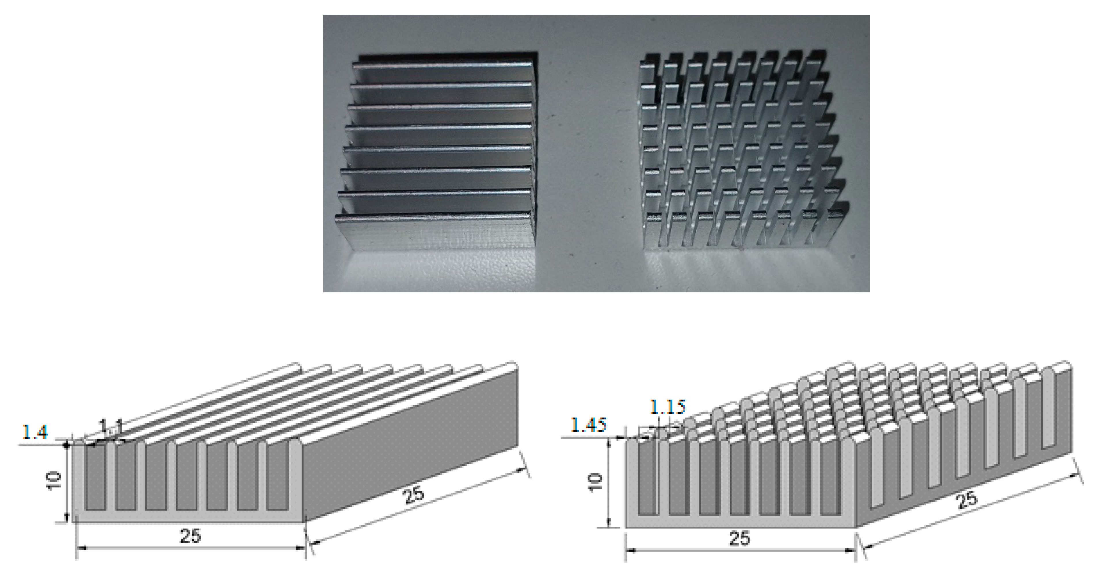
A liquid tank that was made of plexiglass material was placed in a large volume water bath considering the possibility that changes in the ambient temperature during the day may affect the fluid inlet temperature. The temperatures of both tanks were checked by thermometers during the day, and it was observed that they were kept at an approximately constant temperature. In the experimental setup, the fluid was passed through a complete cycle in a closed system and waited until continuous conditions were reached. A radiator was used in the system to remove the excess heat of the fluid that was coming out of the test section and bring it back to its initial condition. The test section was made out of a water block and by placing plate fin type and pin fin type aluminum heat sinks that were made of an Al-6063 alloy and then the experiments were carried out for both base fluid and nanofluids. The material properties of the aluminum heat sinks are given in Table 1. The appearance and dimensions of plate-fin and pin-fin coolers are given in Figure 2. The heat sinks were mounted on the copper base of the water block. To minimize the contact resistance between surfaces as much as possible, a 0.5 mm thick ARCTIC brand thermal pad with high thermal conductivity (6 W/mK) was used.
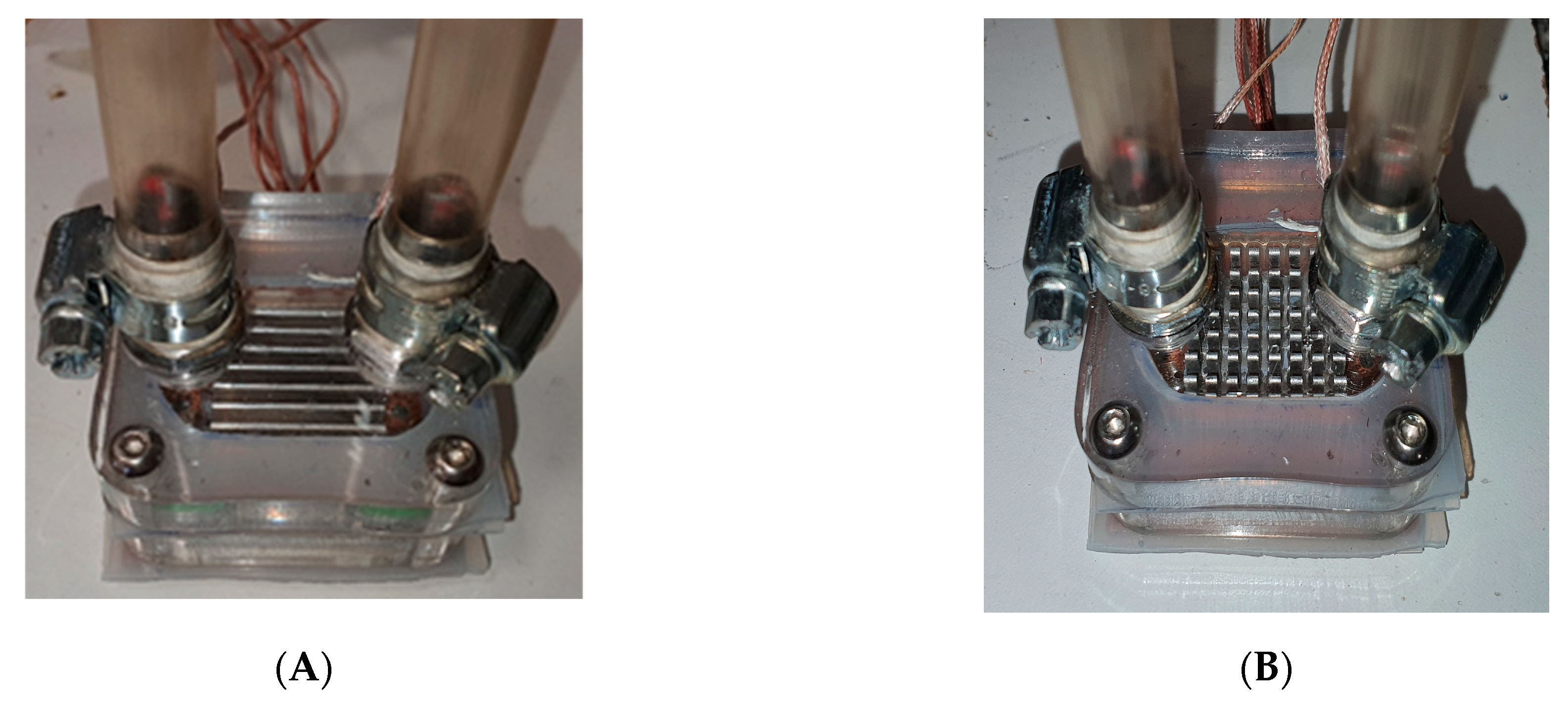
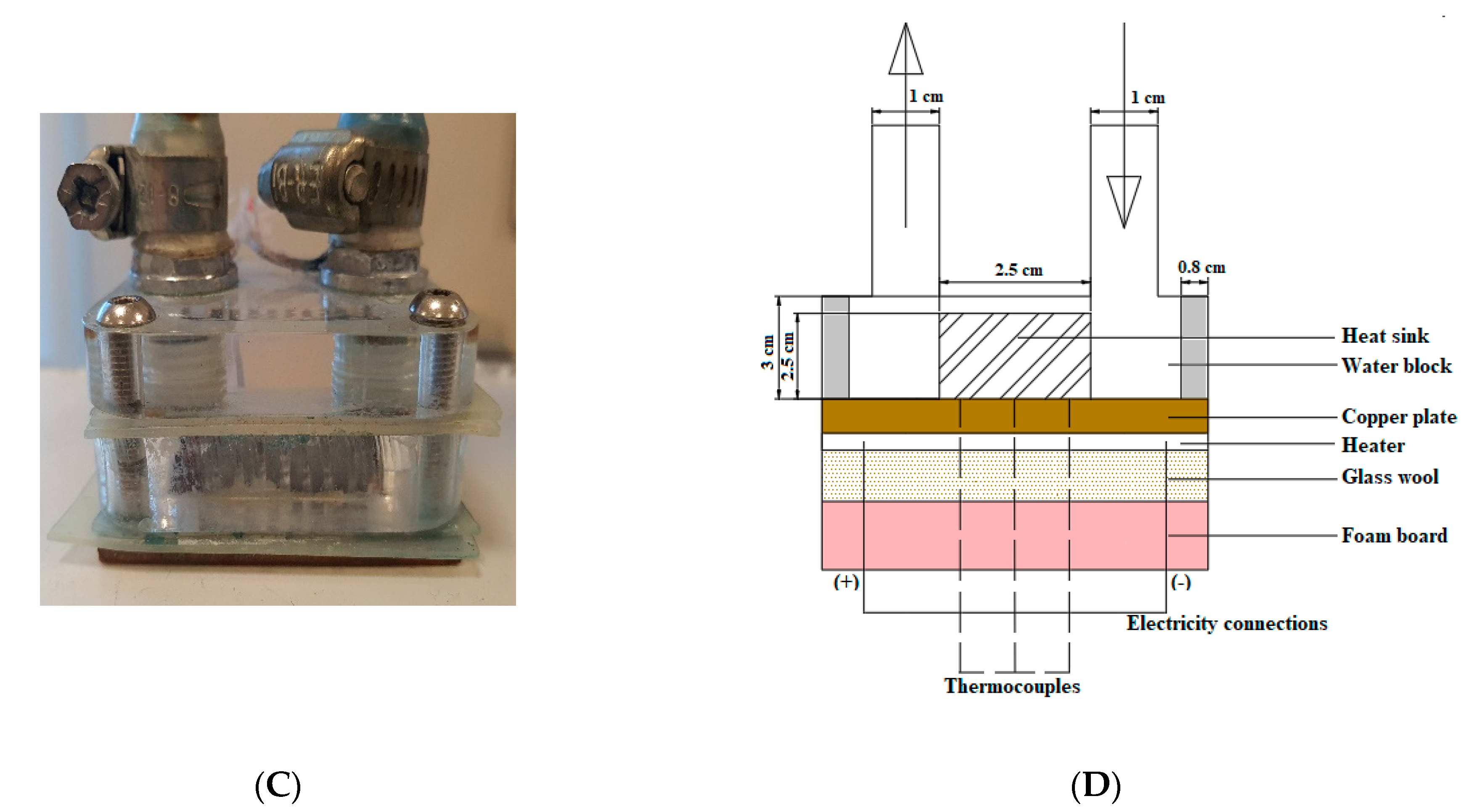
The test section was made of a plexiglass material and the lower part consisted of a copper plate with dimensions of 5 × 5 cm2. The aluminum heat sinks were attached to this copper surface using a thermal pad. To represent CPUs in computers, a heater with a resistance of 88 ohms, with the same dimensions as the copper surface, was placed in the lower part of the test section. The view and schematic drawing of the test section are given in Figure 3 in detail. Glass wool and foamboard material with a thickness of 5 × 5 × 5 cm3 were used to provide insulation at the bottom of the test section.
A total of 9 thermocouples and 2 thermometers were used to measure the temperatures in the experiments. There were three thermocouples that were placed in the lower part of the water block which is made of copper to measure the surface temperature. A total of four thermocouples were placed at the top and bottom of the insulation material to determine conduction losses. A total of two thermocouples were placed at both ends of the water block to measure the inlet and the outlet temperature of the fluid.
2.2. Nanofluid Preparation
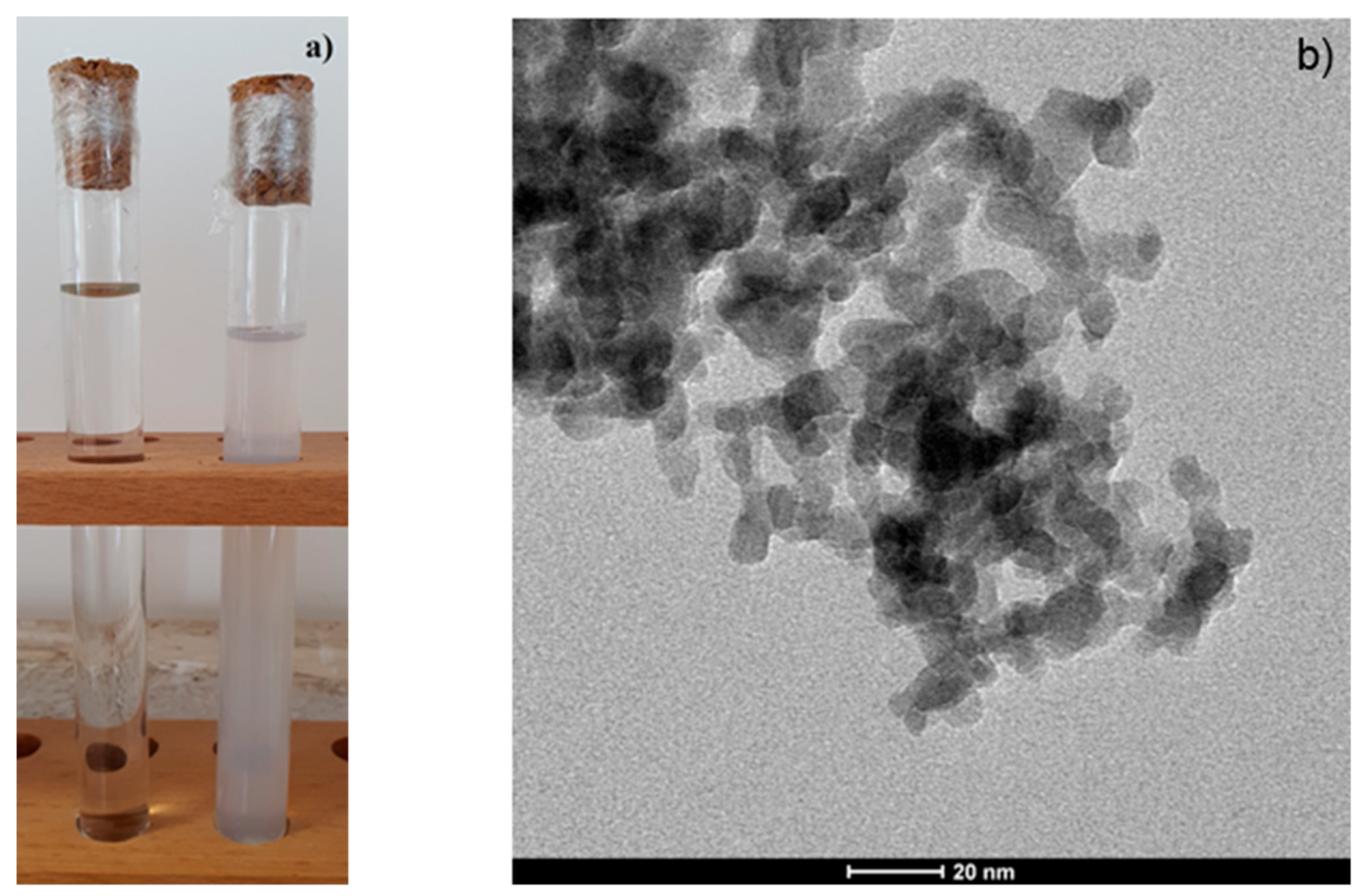
The appearance of the base fluid (pure water) and the Al2O3-H2O nanofluid that was prepared at 0.1% mass fraction are given in Figure 4a. While preparing the nanofluid, Al2O3 nanoparticles that were named Aeroxide Alu 130 (Evonik Ind. AG, Essen-Germany) were used. The mixtures were then subjected to ultrasonic mixing (Elmasonic S100 H, 50 Hz, Elma Schmidbauer GmbH, Singen-Germany) for 2 h to break up any particle aggregates. A TEM image of the Al2O3-H2O nanofluid that was prepared at 0.1% mass fraction is given in Figure 4b. The size and morphology of the Al2O3 particles were examined by using FEI Transmission Electron Microscope (CTEM). The instrument was worked at 120 kV accelerating voltage. The Al2O3 particles were deposited on a carbon-coated copper grid for analysis. The image revealed partially agglomerated particles which have a spherical shape and a size that was less than 20 nm The properties of the Al2O3 nanoparticles are given in Table 2.
The thermophysical properties of the base fluid and nanofluid are given in Table 3. The viscosity of the nanofluid was measured with a viscometer (Fungi Lab ALPL, Barcelona, Spain) and the density was measured with a pycnometer with a volume of 25 mL. It used the literature values at the specific heat capacity [44] and thermal conduction coefficient of nanofluid [45].
In this study, the mass concentration was used for the nanofluid. The relationship between the mass and volumetric concentration was calculated as below [10]:
where φ, ω, ρp, and ρnf are volumetric concentration, mass concentration, particle density, and the density of nanofluid, respectively.
To calculate the specific heat of the nanofluid, the specific heat values of both the base fluid and the nanoparticle were used. The following equation was used to calculate the specific heat of the nanofluid [10]:
2.3. Analysis of Experimental Data
According to the data that were obtained from the experimental study, the net amount of heat that was transferred from the electric heater to the fluid was calculated from the equation below:
In the given equation, , , and represents the net heat rate that was given to the fluid, the heat that was given off from the electric heater, and the heat losses by conduction, respectively.
The amount of heat that was given from the electric heater and the heat loss by conduction were calculated from the equations that are given below. The heat loss by conduction from the lower part of the test area was calculated from the temperature values that were obtained from the T-type thermocouples that were placed on the lower and upper parts of the insulation material, using Fourier’s heat conduction equation.
The amount of voltage that was applied for the heater was V and its resistance is R. In the calculation of conduction loss, k, As, ΔT, and Δx were the thermal conductivity coefficient, surface area, temperature difference, and insulation thickness, respectively. Radiation losses were neglected in this study. The conduction losses in insulation materials were calculated and found to be approximately 0.55% of the total heat transfer rate. In addition, since the side and top parts of the water block have very small surface areas, the conduction losses from these surfaces were also neglected.
The amount of heat that was transferred to the fluid by convection per unit area was calculated as below:
The mean surface temperature of the test area was determined as follows depending on the fluid inlet temperature:
Here represents the mean surface temperature of the heat sink, and Ti represents the inlet temperature of the fluid to the test section. The TSmean was calculated by averaging the surface temperatures (TSmean = (T1 + T2 + T3)/3).
The mean convection heat transfer amount and the mean Nusselt number were calculated according to the following equations:
The thermal resistance was calculated from the equation given below [11]:
The thermal performance of the Al2O3-H2O nanofluid was calculated from the following equation [11]:
The required pumping power was calculated as below [11]:
Here, is volumetric flow rate and ∆P is pressure difference between test section’s inlet and outlet.
To evaluate the overall performance of finned heat sinks, both the thermal and hydraulic performance of the heat sink must be considered. Therefore, a performance index [46] was given as below:
2.4. Uncertainty Analysis
To determine the reliability of the results that were obtained from the experimental study, an uncertainty analysis was performed on all the measured variables and on the quantities that were calculated from the measurement results.
Uncertainties were evaluated according to the standard procedures that were reported in the literature [47]. Variable f was a dependent variable that was related to independent variables x and y, and the uncertainty was calculated as given below:
The characteristics and sensitivities of the measuring instruments that were used in the experimental study are given in Table 4.
Overall, the uncertainty in the convection coefficient was calculated as ±1.49% and for the mean Nusselt number around ±2.071%.
3. Results and Discussion
In this present study, the effect of different fin surfaces (plate fin and pin fin) on heat transfer was investigated by using nanofluids in CHIP cooling. In the experiments, firstly measurements were made using the empty surface and the base fluid. Afterwards, measurements were made with the Al2O3-H2O nanofluid with a mass fraction of 0.1% (w/w), and the results were compared with the results that were obtained with the base fluid.
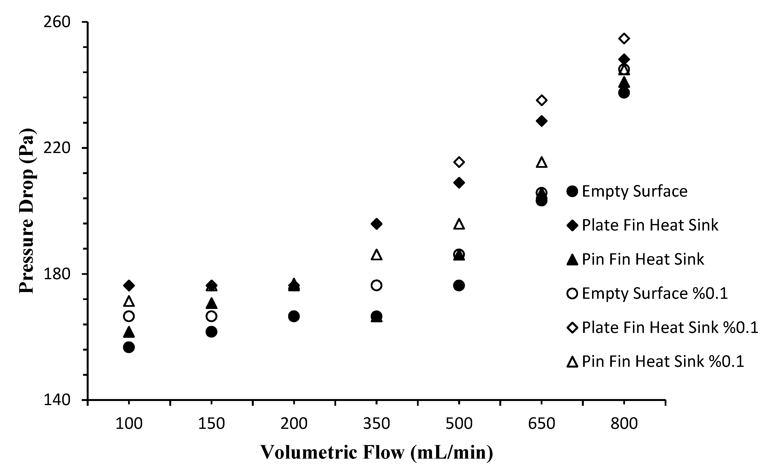
In Figure 5, the pressure drops were given according to the use of base fluid and nanofluid for empty surface, plate fin, and pin fin through the water block. As seen in the figure, the amount of pressure drop that was occurring in the use of base fluid and nanofluid was very close to each other. However, with the use of plate and pin fin heat sinks, it was observed that the pressure difference between the fluids increased significantly. In the case of using both the base fluid and nanofluid at lower volumetric flow rates (from 100 mL/min to 200 mL/min), the pressure drop for empty surface, plate fin, and pin fin remained almost the same while this drop increased rapidly as the flow rate increased. To make an evaluation for the base fluid, when all the surfaces were considered, it was seen that the pressure drop on the empty surface was less than that on the finned surfaces. Considering the nanofluid, more pressure drop was observed on the empty surface compared to the base fluid due to its high viscosity. On the finned surfaces, on the other hand, it was seen that the amount of pressure drop increases even more with the effect of both viscosity and increasing surface area using the nanofluid as a working fluid. As the volumetric flow rate increased, it was seen that the pressure drop was higher than the base fluid due to flow frictions in the use of nanofluids.
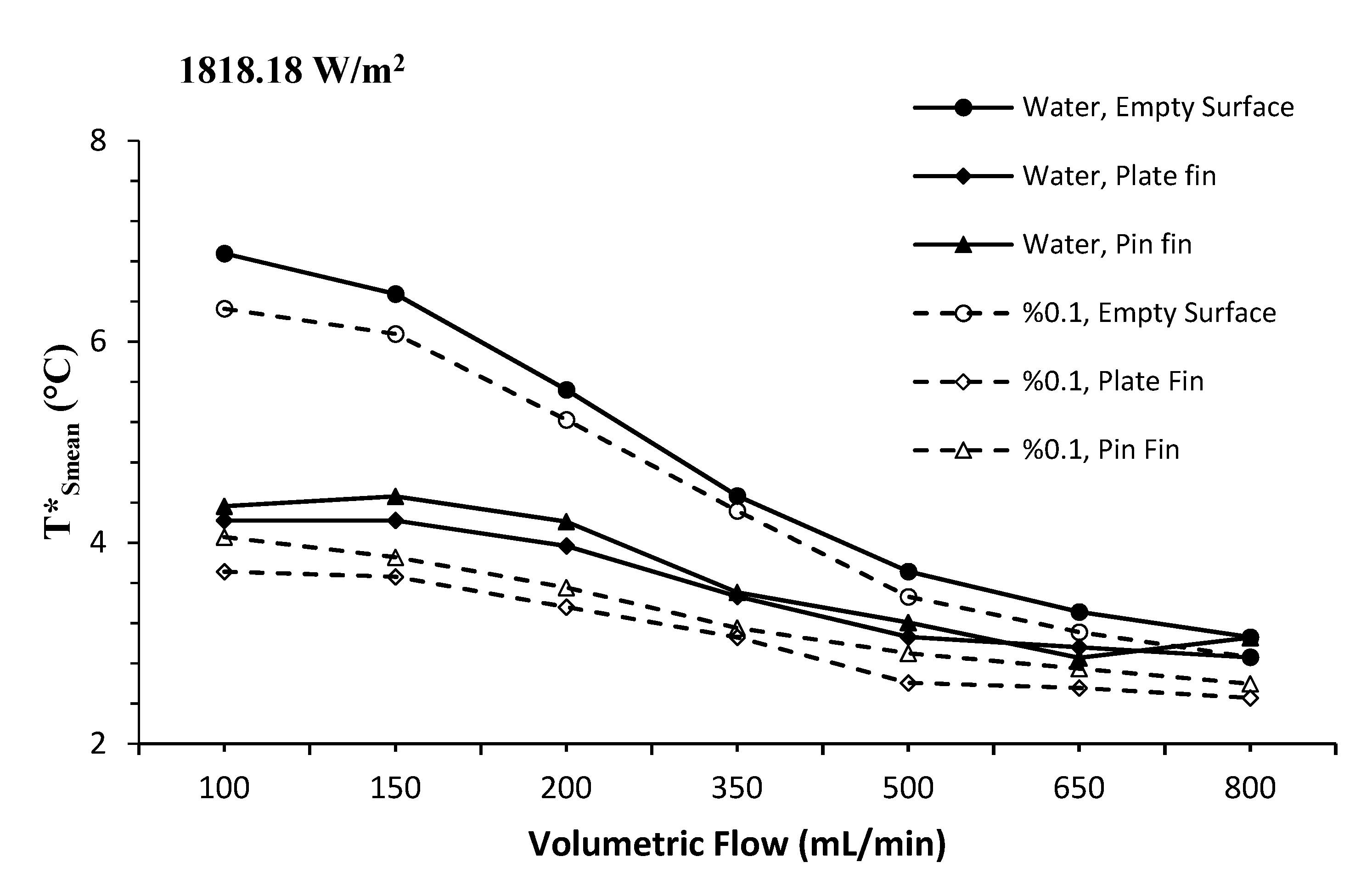
The change in the mean surface temperature according to different volumetric flow rates at 1818.18 W/m2 is given in Figure 6. It was observed that the use of nanofluids reduces the mean surface temperature in all the surface types, due to its high thermal conductivity compared to the base fluid. It was clearly seen in the results that were obtained for both the base fluid and the nanofluid that the finned surfaces have a positive effect on heat transfer. Moreover, with the addition of the nanofluid’s effect of removing heat from these surfaces, it was clearly seen from the figure that the temperature values decrease further. It was also observed that these temperature values approached each other with the increasing volumetric flow rate.
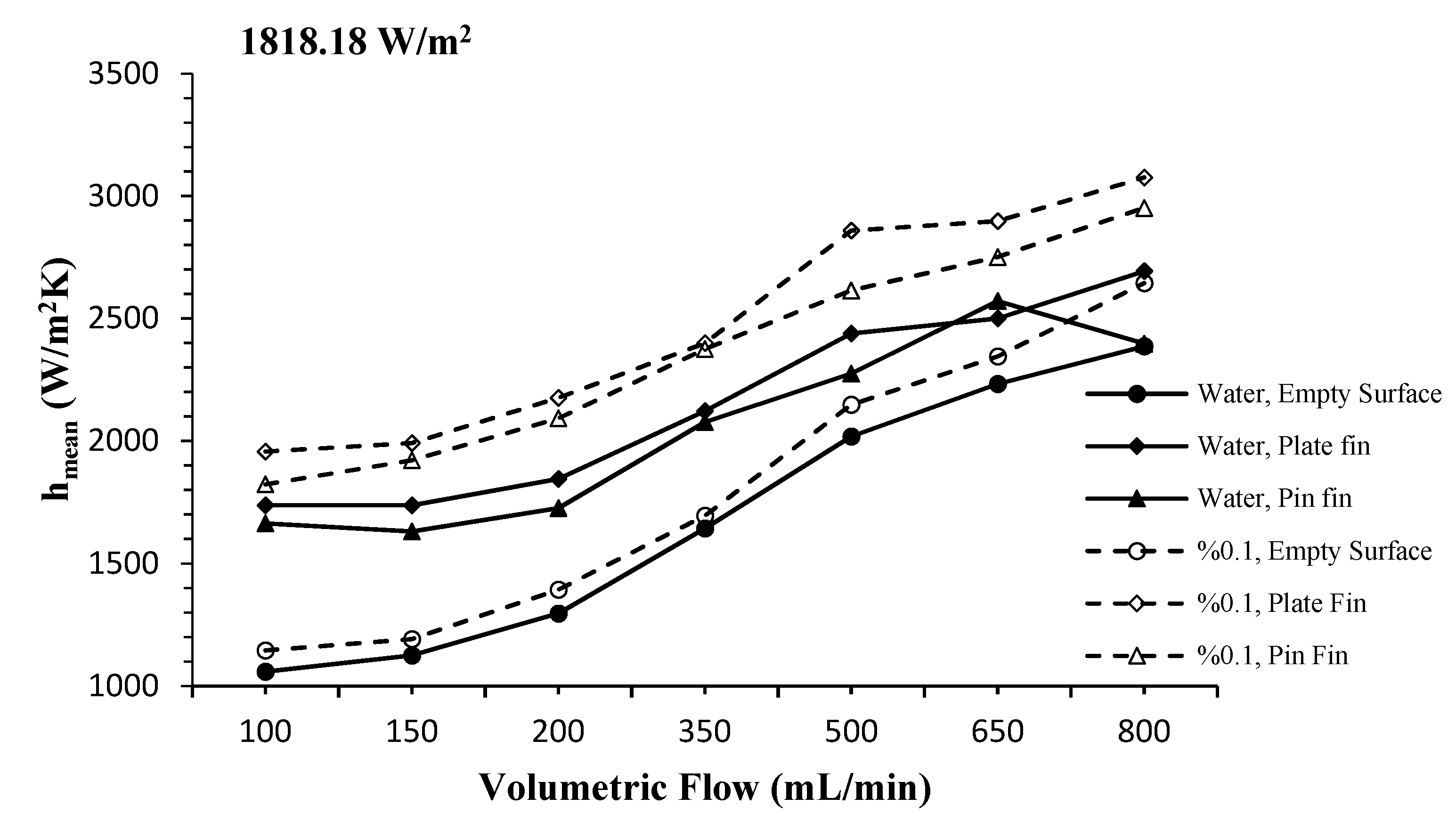
The variation of the mean convective heat transfer coefficient according to different volumetric flow rates at 1818.18 W/m2 for all surfaces where both fluids were used is given in Figure 7. The mean convective heat transfer coefficient increased for all the surfaces with increasing volumetric flow rate. In the case of using the nanofluid, it was clearly seen that the plate fin heat sink increased the heat transfer more than the empty surface and pin thin heat sink due to the intense solid-liquid interaction.
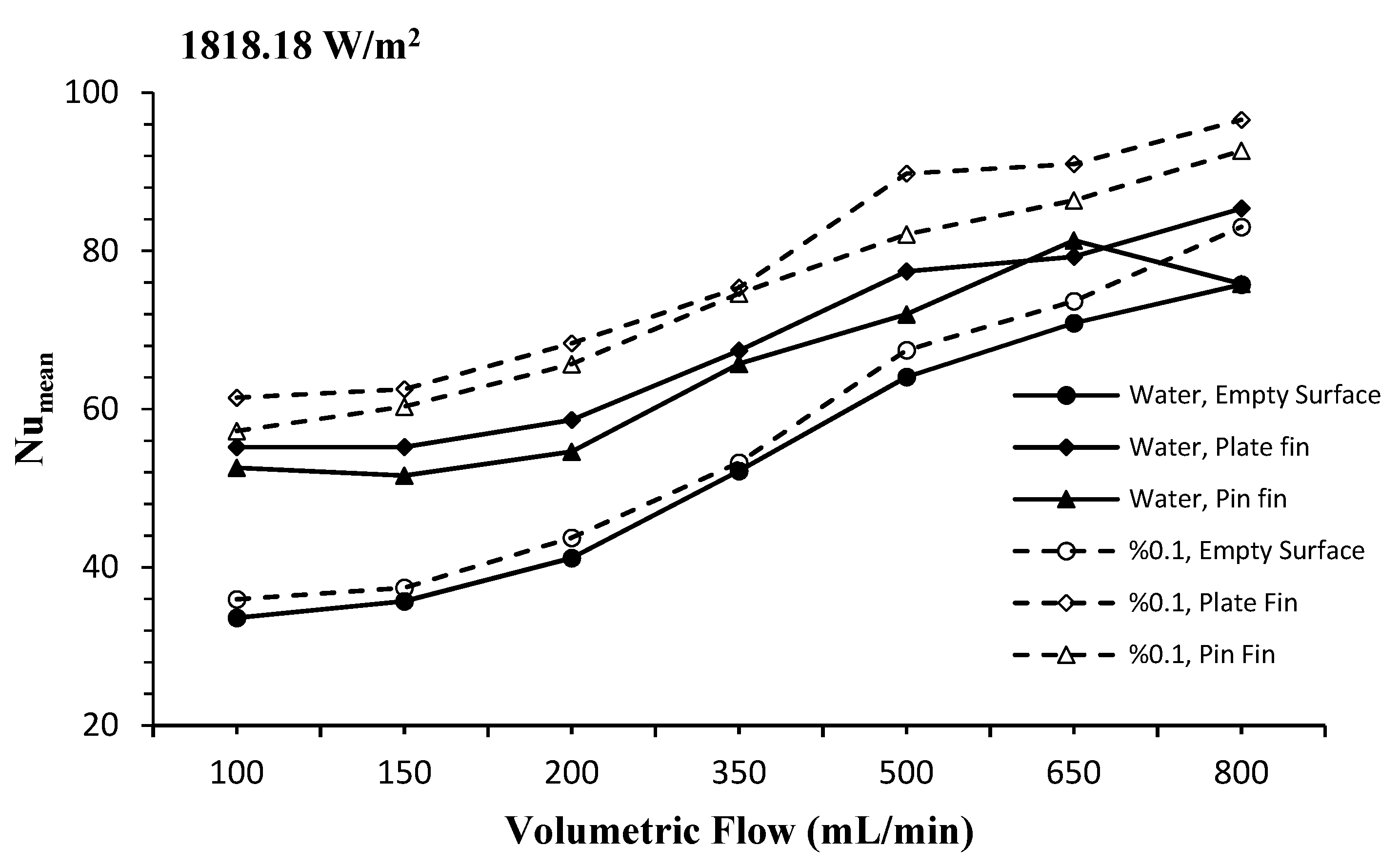
The variations of the mean Nusselt number with different volumetric flow rates at 1818.18 W/m2 is given in Figure 8. It was observed that the mean Nusselt number for all cases increased as the volumetric flow rate increased. By using both nanofluid and finned surfaces, the amount of heat that was transferred from the surfaces was found to be higher than the base fluid. The results that were obtained from the use of nanofluid for the empty surface provided a 10.5% improvement in heat transfer compared to the base fluid. Using the base fluid, the mean Nusselt number improved by 64.2% and 56.4% for the plate fin and pin fin heat sinks, respectively. The maximum improvement in heat transfer was determined as 82.8% and 70.2%, in the use of both nanofluid and plate fin and pin fin heat sinks, respectively. When evaluated in terms of the amount of improvement in heat transfer, it was observed that the plate fin cooler was more effective in surface cooling with the use of nanofluids.
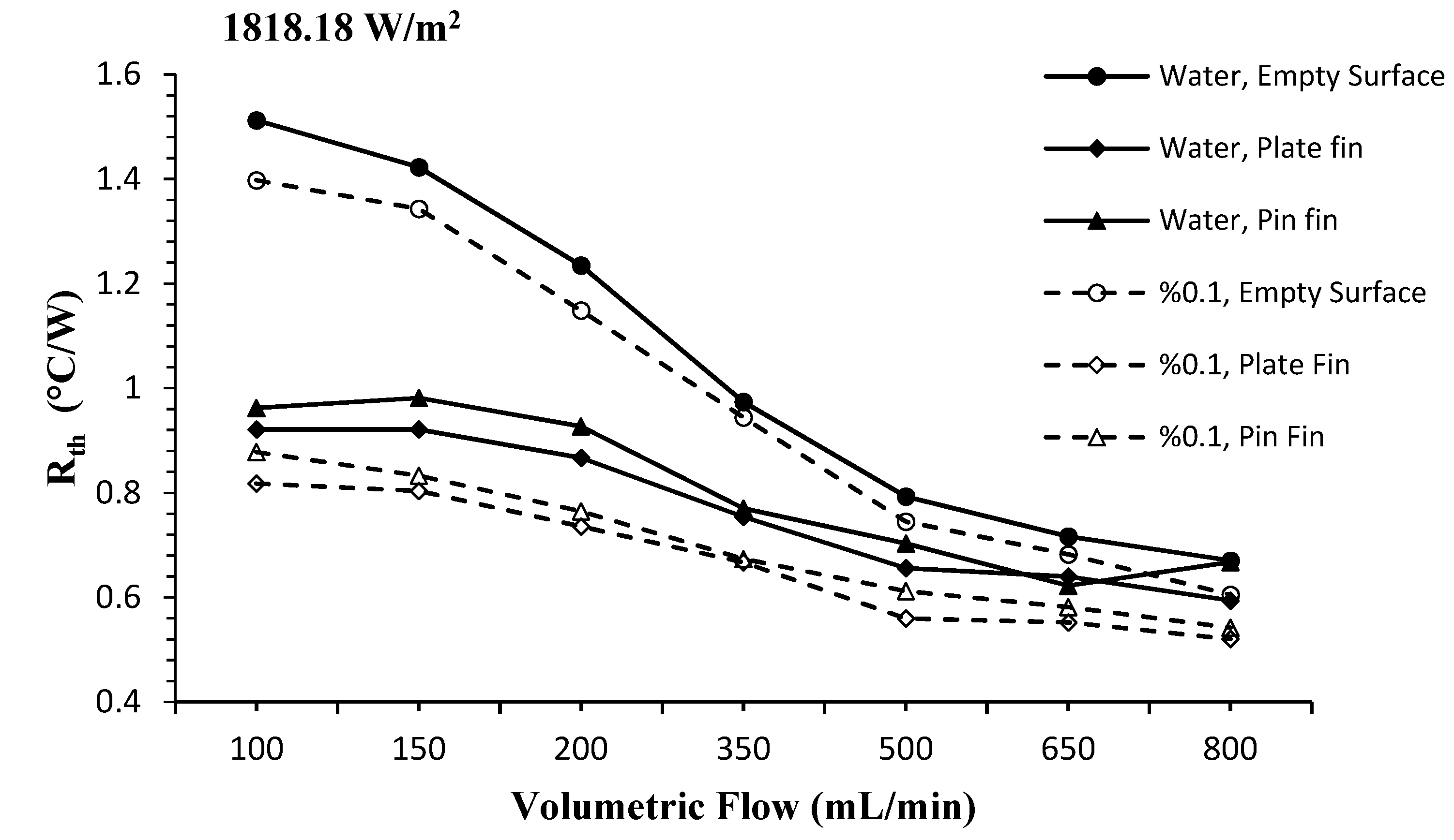
The variation of the thermal resistance according to volumetric flow rate at 1818.18 W/m2 is given in Figure 9. As seen in the figure, the highest thermal resistance values were observed at volumetric flow rate of 100 mL/min in the case of the base fluid and the empty surface. When the values that were obtained for the base fluid and nanofluid were compared, the thermal resistance values on all the surfaces were higher in the base fluid. In addition, a decrease in the thermal resistance was observed with increasing volumetric flow rate for all cases. While this drop in thermal resistance occurred faster at low volumetric flow rates, on the contrary it was slower at high values.
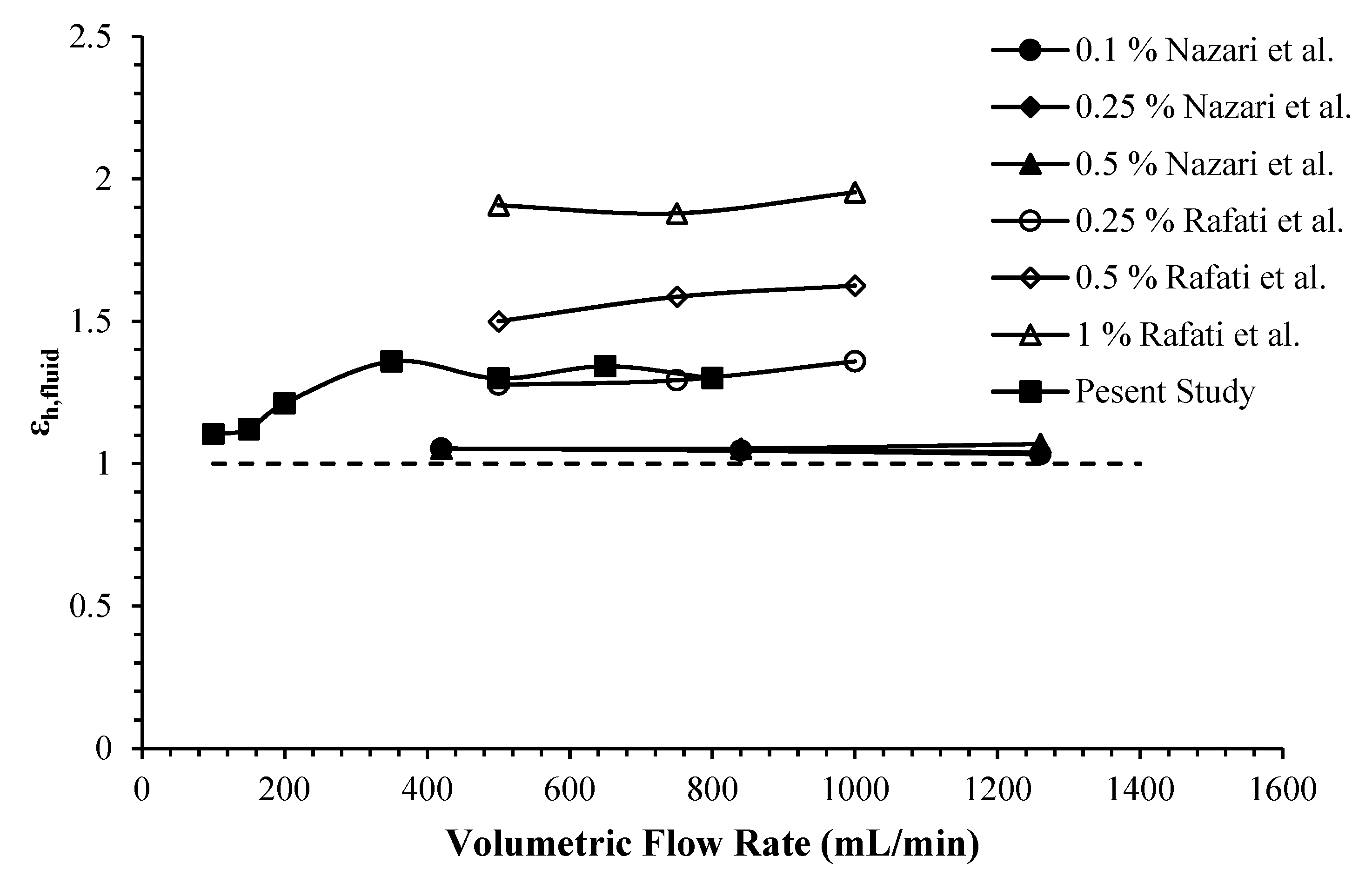
To compare the thermal performance of the nanofluid with the base fluid, the empty surface was taken as a reference. The graph showing the variation of the thermal performance of the nanofluid with different volumetric flow rates was drawn for 454.54 W/m2 in Figure 10. As a result of the calculations, it was observed that the heat transfer performance of the nanofluid was much higher than the base fluid. An increase in the thermal performance of nanofluids was observed with increasing volumetric flow rate. Slight fluctuations in the thermal performance occurred at certain volumetric flow rates. It was estimated that these fluctuations in thermal performance were due to the increased volumetric flow rate and the inability of the nanofluid to have sufficient time for heat transfer within the water block. Similar results were seen in the experimental work of Shah et al. [11]. In addition, the thermal performance of the nanofluid in the figure was compared with other studies in the literature [2,3] using a water block and Al2O3-H2O nanofluid. The thermal performance of the nanofluid that was used in this study was found to be close to the thermal performance values that were obtained from the studies. The differences seen in the graph between the studies occurred due to the concentration of the nanofluid, the geometry of the test region, and the parameters of the studies.
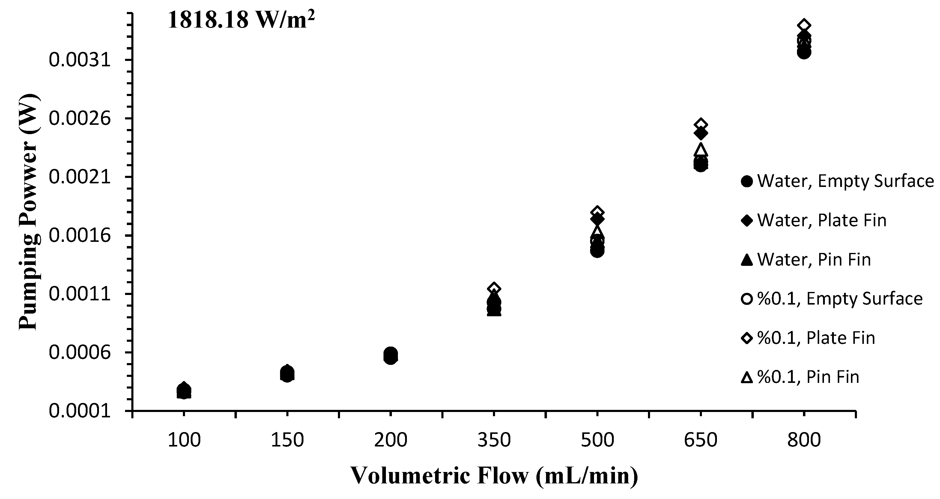
The effect of the volumetric flow rate on the fluid pumping power is given in Figure 11. As seen from the figure, the required pumping power (Pp) increased with increasing volumetric flow rate. In the case of using empty surface and base fluid, the pumping power was at a minimum for all the flow rates, while more pumping power was needed for both fluids in the case of adding fin heat sinks. The greatest increase in the required pumping power was observed in the use of nanofluid and plate fin heat sink.
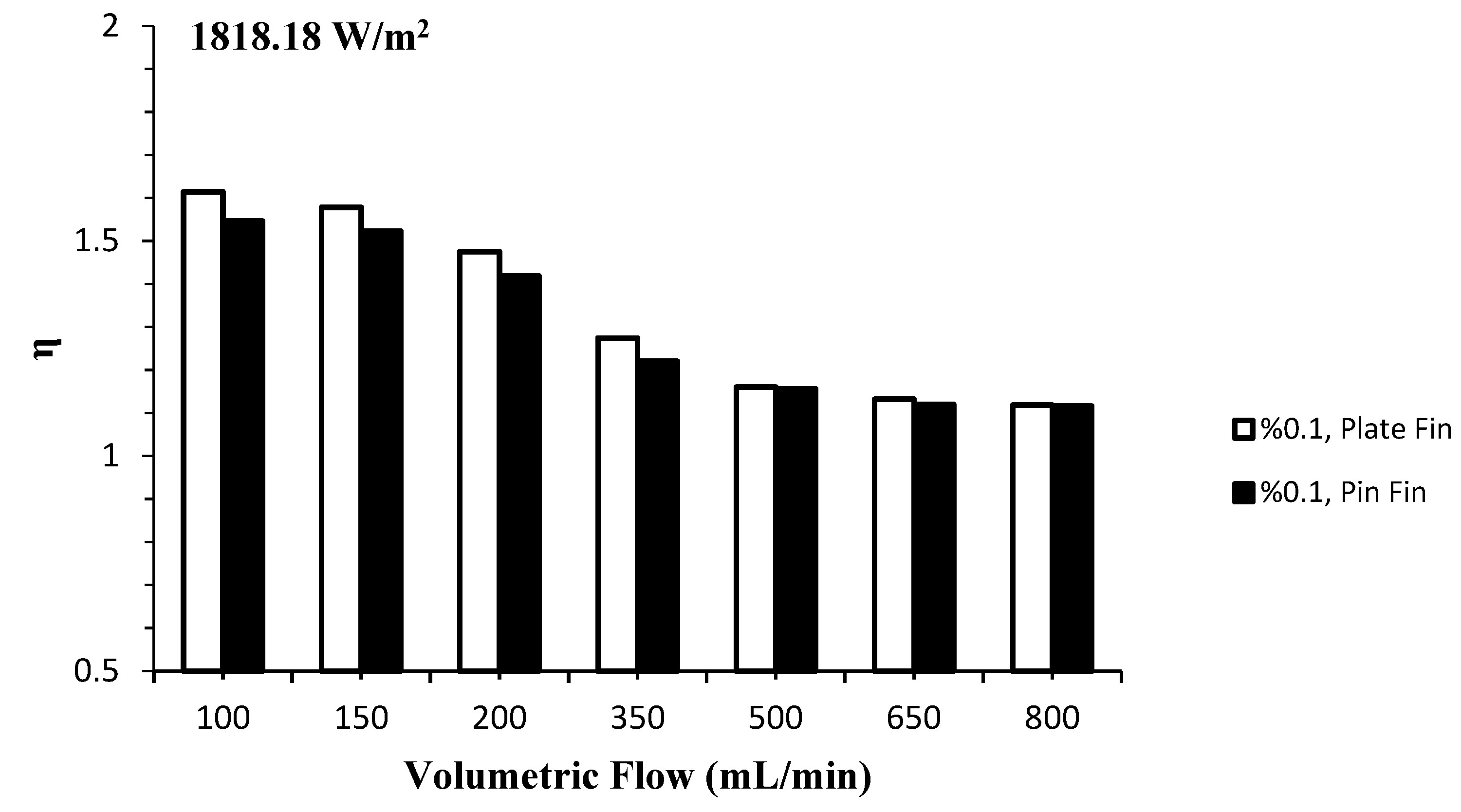
To determine which fin is better than the other in terms of performance in nanofluids, the performance index analysis that was given in equation 13 was performed. In the case of using nanofluid, the variation of the performance index of both the finned heat sinks with volumetric flow rates is given in Figure 12. If the performance index value is less than unity, it is understood that the pressure losses are more dominant than the heat transfer, and if it is greater than unity, the heat transfer is more dominant than the pressure losses. As seen in the figure, the lowest performance index was obtained on the pin fin surface, while the highest performance index was obtained on the plate fin surface. In addition, it was observed that the performance index values of all the surfaces approximately approached each other at high volumetric flow rate.
4. Conclusions
In this study, the heat transfer from plate fin and pin fin heat sinks that were placed in a water block was investigated. Both the basic fluid (pure water) and the Al2O3-H2O nanofluid with a mass fraction of 0.1% were used as cooling fluids. The measurements were taken for the volumetric flow rates that ranged from 100 to 800 mL/min and the constant heat flux values of 454.54 W/m2 and 1818.18 W/m2. The results that were obtained from the finned surfaces for the base fluid and the nanofluid were compared with the empty surface and the following results were presented:
- For all cases, it was observed that the mean surface temperatures decreased rapidly with increasing volumetric flow rate. However, after a certain flow rate (650 mL/min), it was observed that the amount of decrease in the mean average surface temperature decreased.
- With the use of nanofluid on the empty surface, a greater decrease in the mean surface temperatures was observed compared to the base fluid. Accordingly, the maximum improvement amount that was obtained by using nanofluids at the mean surface temperatures was determined as 10.5%.
- By using plate fin and pin fin heat sinks with a base fluid, an improvement of 27.48% and 24.57% was observed in the surface temperatures compared to the empty surface, respectively. In the use of nanofluid with the plate and pin-finned heat sink instead of the base fluid, 35.73% and 29.49% improvements in the surface temperatures were obtained.
- With the use of nanofluid on the empty surface, a 22.15% improvement was observed in the mean Nusselt number compared to the base fluid.
- In the use of pin fin and plate fin heat sinks with the base fluid, 56.4% and 64.2% improvements in the mean Nusselt number were obtained, respectively. The maximum improvement in the mean Nusselt number that was obtained using nanofluid with pin fin and plate fin heat sinks was determined as 70.2% and 82.8%, respectively.
- When the performance index was examined, it was seen that the use of a plate fin heat sink was more suitable than the pin fin heat sink in the cooling of electronic systems. Although the performance index that was obtained for the two fin types approached each other with increasing volumetric flow rate, the best result was obtained in the plate fin heat sink.
- With the use of nanofluid on the empty surface, no significant increase in pressure drop and pumping power was observed compared to the base fluid. However, with the use of finned heat sinks, the pressure drop and the increase in pumping power for both fluids became more pronounced. When the performance index was examined, it was determined that this increase in the use of finned heat sinks and nanofluids could be ignored according to the amount of improvement in heat transfer.
- Commercial Al2O3 nanoparticles (Alu 130) which were used in this study promise hope for both nanofluid research and the production of commercial nanofluids for electronic cooling.
Author Contributions
Experimental setup, O.O. and A.D.; calibration, O.O. and A.D.; measurements, O.O.; formal analysis, O.O. and A.D., investigation, O.O., A.D. and M.A.; resources, O.O., A.D. and M.A.; data evaluation, O.O., A.D. and M.A.; Nanofluid preparation, M.A.; thermophysical property measurement, M.A. and O.O.; writing—original draft preparation, O.O., A.D. and M.A.; writing—review and editing, O.O., A.D. and M.A.; project administration, O.O. and A.D.; funding acquisition, O.O. All authors have read and agreed to the published version of the manuscript.
Funding
This research received no external funding.
Data Availability Statement
The data presented in this study are available on request from the corresponding author.
Acknowledgments
We also thank the METU-Central Laboratory (ODTU-Merlab) for their contribution to CTEM analysis.
Conflicts of Interest
The authors declare no conflict of interest.
Abbreviations
| Symbols | |
| As | Water block surface area [m2] |
| Cp | Specific heat [J/kgK] |
| Hydraulic diameter [m] | |
| hmean | Mean convective heat transfer coefficient [W/m2K] |
| k | Thermal conductivity [W/mK] |
| kf | Fluid conductive heat transfer coefficient [W/mK] |
| Numean | Mean Nusselt number [-] |
| Pp | Pumping power [W] |
| Conduction heat transfer rate [W] | |
| Convection heat transfer rate [W] | |
| Heat transfer rate from heater [W] | |
| qconv. | Convection heat flux [W/m2] |
| R | Electrical resistance [Ohm] |
| Thermal resistance [°C/W] | |
| Ti | Fluid inlet temperature [°C] |
| T*Smean | Mean Surface temperature [°C] |
| V | Voltage [V] |
| Volumetric flow rate [mL/min] | |
| ΔT | Temperature difference [K] |
| Δx | Thickness [m] |
| Uncertainty [-] | |
| ε | Thermal performance of nanofluid [-] |
| η | Performance index [-] |
| ρ | Density (g/cm3) |
| ν | Viscosity [m2/s] |
| Volumetric concentration [-] | |
| Mass fraction [-] | |
| Subscripts | |
| bf | Base fluid |
| nf | Nanofluid |
| p | Nanoparticle |
| s | Surface |
| f | Fluid |
| Abbreviations | |
| PPI | Pores Per Inch |
References
- Choi, S.U.S.; Eastman, J.A. Enhancing Thermal Conductivities of Fluids with Nanoparticles; No. ANL/MSD/CP-84938; CONF-951135-29; Argonne National Lab. (ANL): Argonne, IL, USA, 1995. [Google Scholar]
- Nazari, M.; Karami, M.; Ashouri, M. Comparing the thermal performance of water, ethylene glycol, alumina and CNT nanofluids in CPU cooling: Experimental study. Exp. Therm. Fluid Sci. 2014, 57, 371–377. [Google Scholar] [CrossRef]
- Rafati, M.; Hamidi, A.A.; Niaser, M.S. Application of nanofluids in computer cooling systems (heat transfer performance of nanofluids). Appl. Therm. Eng. 2012, 45–46, 9–14. [Google Scholar] [CrossRef]
- Sarafraz, M.M.; Arya, A.; Hormozi, F.; Nikkhah, V. On the convective thermal performance of a CPU cooler working with liquid gallium and CuO/water nanofluid: A comparative study. Appl. Therm. Eng. 2017, 112, 1373–1381. [Google Scholar] [CrossRef]
- Alfaryjat, A.A.; Miron, L.; Pop, H.; Apostol, V.; Stefanescu, M.F.; Dobrovicescu, A. Experimental investigation of thermal and pressure performance in computer cooling systems using different types of nanofluids. Nanomaterials 2019, 9, 1231. [Google Scholar] [CrossRef] [PubMed]
- Selvakumar, P.; Suresh, S. Convective performance of CuO/water nanofluid in an electronic heat sink. Exp. Therm. Fluid Sci. 2012, 40, 57–63. [Google Scholar] [CrossRef]
- Korpys, M.; Al-Rashed, M.; Dzido, G.; Wojcik, J. CPU heat sink cooled by nanofluids and water: Experimental and numerical study. In Proceedings of the 23rd European Symposium on Computer Aided Process Engineering—ESCAPE 23, Lappeenranta, Finland, 9–12 June 2013; pp. 409–414. [Google Scholar]
- Nguyen, C.T.; Roy, G.; Gauthier, C.; Galanis, N. Heat transfer enhancement by using Al2O3-water nanofluid for an electronic liquid cooling system. Appl. Therm. Eng. 2007, 27, 1501–1506. [Google Scholar] [CrossRef]
- Turgut, A.; Elbasan, E. Nanofluids for electronics cooling. In Proceedings of the 2014 IEEE 20th International Symposium for Design and Technology in Electronic Packaging (SIITME), Bucharest, Romania, 23–26 October 2014; pp. 35–37. [Google Scholar]
- Qi, C.; Hu, J.; Liu, M.; Guo, L.; Rao, Z. Experimental study on thermo-hydraulic performances of CPU cooled by nanofluids. Energy Convers. Manag. 2017, 153, 557–565. [Google Scholar] [CrossRef]
- Khaleduzzaman, S.S.; Mahbubul, I.M.; Sohel, M.R.; Saidur, R.; Selvaraj, J.; Ward, T.A.; Niza, M.E. Experimental analysis of energy and friction factor for titanium dioxide nanofluid in a water block heat sink. Int. J. Heat Mass Transf. 2017, 115, 77–85. [Google Scholar] [CrossRef]
- Arya, A.; Shahmiri, S.; Nikkhah, V.; Sarafraz, M.M. Cooling of high heat flux flat surface with nanofluid assisted convective loop: Experimental assessment. Arch. Mech. Eng. 2017, 4, 519–531. [Google Scholar] [CrossRef]
- Ho, C.J.; Chen, W.C. An experimental study on thermal performance of Al2O3/water nanofluid in a minichannel heat sink. Appl. Therm. Eng. 2013, 50, 516–522. [Google Scholar] [CrossRef]
- Sukhor, N.B.; Tijani, A.S.; Kubenthiran, J.; Muritala, I.K. Computational modeling of thermal characteristics of hybrid nanofluid in micro-pin fin heat sink for electronic cooling. Int. J. Green Energy 2021, 18, 1027–1045. [Google Scholar] [CrossRef]
- Hasan, M.I. Investigation of flow and heat transfer characteristics in micro pin fin heat sink with nanofluid. Appl. Therm. Eng. 2014, 63, 598–607. [Google Scholar] [CrossRef]
- Sajid, M.U.; Ali, H.M.; Sufyan, A.; Rashid, D.; Zahid, S.U.; Rehman, W.U. Experimental investigation of TiO2–water nanofluid flow and heat transfer inside wavy mini-channel heat sinks. J. Therm. Anal. Calorim. 2019, 137, 1279–1294. [Google Scholar] [CrossRef]
- Sajid, M.U.; Ali, H.M.; Bicer, Y. Exergetic performance assessment of magnesium oxide–water nanofluid in corrugated minichannel heat sinks: An experimental study. Int. J. Energy Res. 2020, 46, 9985–10001. [Google Scholar] [CrossRef]
- Miry, S.Z.; Roshani, M.; Hanafizadeh, P.; Ashjaee, M.; Amini, F. Heat Transfer and Hydrodynamic Performance Analysis of a Miniature Tangential Heat Sınk Using Al2O3–H2O and TiO2–H2O Nanofluids. Exp. Heat Transf. 2016, 29, 535–560. [Google Scholar] [CrossRef]
- Sehgal, S.S.; Krishnan, M.; Mohapatra, S.K. Experimental investigation of the effect of flow arrangements on the performance of a micro-channel heat sink. Exp. Heat Transf. 2011, 24, 215–233. [Google Scholar] [CrossRef]
- Sarbazi, Z.; Hormozi, F. Optimization of thermal and hydraulic performance of nanofluid in a rectangular miniature-channel with various fins using response surface methodology. J. Therm. Anal. Calorim. 2019, 137, 711–733. [Google Scholar] [CrossRef]
- Khoshvaght-Aliabadi, M.; Hormozi, F. Heat transfer enhancement by using copper–water nanofluid flow inside a pin channel. Exp. Heat Transf. 2015, 28, 446–463. [Google Scholar] [CrossRef]
- Khoshvaght-Aliabadi, M.; Hassani, S.M.; Mazloumi, S.H. Comparison of hydrothermal performance between plate fins and plate-pin fins subject to nanofluid-cooled corrugated miniature heat sinks. Microelectron. Reliab. 2017, 70, 84–96. [Google Scholar] [CrossRef]
- Khoshvaght-Aliabadi, M.; Mortazavi, S. Combined effects of holes and winglets on chevron plate-fins to enhance the performance of a plate-fin heat exchanger working with nanofluid. Exp. Heat Transf. 2019, 32, 84–599. [Google Scholar] [CrossRef]
- Abdollahi, A.; Mohammed, H.A.; Vanaki, S.M.; Sharma, R.N. Numerical investigation of fluid flow and heat transfer of nanofluids in microchannel with longitudinal fins. Ain Shams Eng. J. 2018, 9, 3411–3418. [Google Scholar] [CrossRef]
- Kumar, V.; Sarkar, J. Particle ratio optimization of Al2O3-MWCNT hybrid nanofluid in minichannel heat sink for best hydrothermal performance. Appl. Therm. Eng. 2020, 165, 114546. [Google Scholar] [CrossRef]
- Fazeli, H.; Pourrajabian, A.; Nikooei, E. Simultaneous optimization of geometric and nanofluid parameters in a rectangular microchannel heat sink. Heat Transf. Eng. 2021, 43, 1–18. [Google Scholar] [CrossRef]
- Khetib, Y.; Alahmadi, A.; Alzaed, A.; Saleem, H.A.; Sharifpur, M.; Kalbasi, R. The effect of pin-fin shapes on heat sink effectiveness in the presence of a turbulent nanofluid regime. Chem. Eng. Commun. 2021, 208, 1–16. [Google Scholar] [CrossRef]
- Ali, H.M.; Arshad, W. Thermal performance investigation of staggered and inline pin fin heat sinks using water based rutile and anatase TiO2 nanofluids. Energy Convers. Manag. 2015, 106, 793–803. [Google Scholar] [CrossRef]
- Ali, H.M.; Arshad, W. Effect of channel angle of pin-fin heat sink on heat transfer performance using water based graphene nanoplatelets nanofluids. Int. J. Heat Mass Transf. 2017, 106, 465–472. [Google Scholar] [CrossRef]
- Hwang, K.S.; Jang, S.P.; Choi, S.U.S. Flow and convective heat transfer characteristics of water-based Al2O3 nanofluids in fully developed laminar flow regime. Int. J. Heat Mass Transf. 2009, 52, 193–199. [Google Scholar] [CrossRef]
- Kim, S.; Tserengombo, B.; Choi, S.H.; Noh, J.; Huh, S.; Choi, B.; Chung, H.; Kim, J.; Jeong, H. Experimental investigation of heat transfer coefficient with Al2O3 nanofluid in small diameter tubes. Appl. Therm. Eng. 2019, 146, 346–355. [Google Scholar] [CrossRef]
- Zhao, N.; Guo, L.; Qi, C.; Chen, T.; Cui, X. Experimental study on thermo-hydraulic performance of nanofluids in CPU heat sink with rectangular grooves and cylindrical bugles based on exergy efficiency. Energy Convers. Manag. 2019, 181, 235–246. [Google Scholar] [CrossRef]
- Bahiraei, M.; Mazaheri, N.; Daneshyar, M.R. Employing elliptical pin-fins and nanofluid within a heat sink for cooling of electronic chips regarding energy efficiency perspective. Appl. Therm. Eng. 2021, 183, 116159. [Google Scholar] [CrossRef]
- Ambreen, T.; Kim, M.H. Comparative assessment of numerical models for nanofluids’ laminar forced convection in micro and mini channels. Int. J. Heat Mass Transf. 2017, 115, 513–523. [Google Scholar] [CrossRef]
- Ambreen, T.; Kim, M.H. Effects of variable particle sizes on hydrothermal characteristics of nanofluids in a microchannel. Int. J. Heat Mass Transf. 2018, 120, 490–498. [Google Scholar] [CrossRef]
- Ambreen, T.; Kim, M.H. Effect of fin shape on the thermal performance of nanofluid-cooled micro pin-fin heat sinks. Int. J. Heat Mass Transf. 2018, 126, 245–256. [Google Scholar] [CrossRef]
- Ambreen, T.; Saleem, A.; Park, C.W. Numerical analysis of the heat transfer and fluid flow characteristics of a nanofluid-cooled micropin-fin heat sink using the Eulerian-Lagrangian approach. Powder Technol. 2019, 345, 509–520. [Google Scholar] [CrossRef]
- Ambreen, T.; Saleem, A.; Ali, H.M.; Shehzad, S.A.; Park, C.W. Performance analysis of hybrid nanofluid in a heat sink equipped with sharp and streamlined micro pin-fins. Powder Technol. 2019, 355, 552–563. [Google Scholar] [CrossRef]
- Ambreen, T.; Saleem, A.; Tanveer, M.; Anirudh, K.; Shehzad, S.A.; Park, C.W. Irreversibility and hydrothermal analysis of the MWCNTs/GNPs-based nanofluids for electronics cooling applications of the pin-fin heat sinks: Multiphase Eulerian-Lagrangian modeling. Case Stud. Therm. Eng. 2022, 31, 101806. [Google Scholar] [CrossRef]
- Ambreen, T.; Saleem, A.; Park, C.W. Homogeneous and Multiphase Analysis of Nanofluids Containing Nonspherical MWCNT and GNP Nanoparticles Considering the Influence of Interfacial Layering. Nanomaterials 2021, 11, 277. [Google Scholar] [CrossRef]
- Shehzad, S.A.; Alshuraiaan, B.; Kamel, M.S.; Izadi, M.; Ambreen, T. Influence of fin orientation on the natural convection of aqueous-based nano-encapsulated PCMs in a heat exchanger equipped with wing-like fins. Chem. Eng. Process. Process Intensif. 2021, 160, 108287. [Google Scholar] [CrossRef]
- Ambreen, T.; Saleem, A.; Park, C.W. Thermal efficiency of eco-friendly MXene based nanofluid for performance enhancement of a pin-fin heat sink: Experimental and numerical analyses. Int. J. Heat Mass Transf. 2022, 186, 122451. [Google Scholar] [CrossRef]
- AEROXIDE. Production Information AEROXIDE Alu 130. Available online: https://glenncorp.com/wp-content/uploads/2013/12/AEROXIDE-Alu-130.pdf (accessed on 6 July 2022).
- Calvin, J.J.; Asplund, M.; Zhang, Y.; Huang, B.; Woodfield, B.F. Heat capacity and thermodynamic functions of γ-Al2O3. J. Chem. Thermodyn. 2017, 112, 77–85. [Google Scholar] [CrossRef]
- Prakash, A.; Satsangi, S.; Mittal, S.; Nigam, B.; Mahto, P.K.; Swain, B.P. Investigation on Al2O3 nanoparticles for nanofluid applications—A Review. IOP Conf. Ser. Mater. Sci. Eng. 2018, 377, 012175. [Google Scholar] [CrossRef]
- Pourfarzad, E.; Ghadiri, K.; Behrangzade, A.; Ashjaee, M. Experimental investigation of heat transfer and pressure drop of alumina–water nano-fluid in a porous miniature heat sink. Exp. Heat Transf. 2018, 31, 495–512. [Google Scholar] [CrossRef]
- Holman, J.P. Analysis of experimental data. In Experimental Methods for Engineers, 6th ed.; McGraw-Hill, Inc.: New York, NY, USA, 1994; pp. 49–56. [Google Scholar]
Figure 1.
Picture (A) and schematic (B) of the experimental layout.


Figure 2.
The schematic diagram of the plate fin and pin fin heat sinks (dimensions were given in mm).
Figure 2.
The schematic diagram of the plate fin and pin fin heat sinks (dimensions were given in mm).

Figure 3.
Test section; (A) Plate fin heat sink placed water block; (B) Pin fin heat sink placed water; (C) Side view of the water block; (D) Schematic drawing of heating assembly.
Figure 3.
Test section; (A) Plate fin heat sink placed water block; (B) Pin fin heat sink placed water; (C) Side view of the water block; (D) Schematic drawing of heating assembly.


Figure 4.
(a) The appearance of the base fluid (pure water) and the Al2O3-H2O nanofluid and (b) TEM image of the Al2O3-H2O nanofluid.
Figure 4.
(a) The appearance of the base fluid (pure water) and the Al2O3-H2O nanofluid and (b) TEM image of the Al2O3-H2O nanofluid.

Figure 5.
Pressure drop inside the water block for base fluid and nanofluid in different surfaces.

Figure 6.
Variation of the mean surface temperatures with volumetric flow rate.

Figure 7.
Variation of the mean convective heat transfer coefficients with volumetric flow rates.

Figure 8.
Variation of the mean Nusselt numbers with volumetric flow rates.

Figure 9.
Variations of thermal resistance at different volumetric flow rates.

Figure 10.
Variation of the nanofluid thermal performance with volumetric flow rate (Empty channel) [2,3].

Figure 11.
Pumping power versus the volumetric flow rate at different surface type heat sinks.

Figure 12.
Performance index variations of the plate fin and pin fin heat sinks.


Table 1.
Material properties of the Aluminum heat sinks.
| Density (ρ) | 2700 kg/m3 |
| Thermal Conductivity (k) | 209.5 W/mK |
| Melting Point | 615 °C |
| Dimensions | 2.5 × 2.5 × 1 cm |
Table 2.
Properties of the Al2O3 nanoparticles [43].
Table 2.
Properties of the Al2O3 nanoparticles [43].
| Specific Surface Area | 130 ± 20 m2/g |
| Tamped Density | 50 g/L |
| PH (in %4 dispersion) | 4.4–5.4 |
| Density | 3.27 g/cm3 |
Table 3.
Thermophysical properties of the base fluid and nanofluid.
| Fluids | Density (ρ) (g/cm3) | Viscosity (μ) (kg/ms) | Thermal Conductivity (k) (W/mK) | Specific Heat (Cp) (kJ/kgK) |
|---|---|---|---|---|
| Water | 0.9984 | 0.00098 | 0.5962 | 4182.8 |
| (w/w) 0.1% Al2O3-H2O | 0.9986 | 0.00134 | 0.5973 | 4181.8 |
Table 4.
Features and sensitivities of the measuring instruments.
| Measurement Tools | Sensibility | Uncertainties |
|---|---|---|
| 30-gauge T-type Thermocouples | ±1 °C | 0.015% |
| TT Technic VC-9808+ | ±0.8% + 5 (AC) | 0.14% |
| TT Technic VC-9808+ | ±0.8% + 3 (Ohm) | 0.042% |
| Float Flowmeter | ±3% | 0.03% |
| U manometer | ±0.5 (Pa) | 0.029% |
Publisher’s Note: MDPI stays neutral with regard to jurisdictional claims in published maps and institutional affiliations. |
© 2022 by the authors. Licensee MDPI, Basel, Switzerland. This article is an open access article distributed under the terms and conditions of the Creative Commons Attribution (CC BY) license (https://creativecommons.org/licenses/by/4.0/).
Share and Cite
MDPI and ACS Style
Ozbalci, O.; Dogan, A.; Asilturk, M. Heat Transfer Performance of Plate Fin and Pin Fin Heat Sinks Using Al2O3/H2O Nanofluid in Electronic Cooling. Processes 2022, 10, 1644. https://doi.org/10.3390/pr10081644
AMA Style
Ozbalci O, Dogan A, Asilturk M. Heat Transfer Performance of Plate Fin and Pin Fin Heat Sinks Using Al2O3/H2O Nanofluid in Electronic Cooling. Processes. 2022; 10(8):1644. https://doi.org/10.3390/pr10081644
Chicago/Turabian StyleOzbalci, Oguzhan, Ayla Dogan, and Meltem Asilturk. 2022. "Heat Transfer Performance of Plate Fin and Pin Fin Heat Sinks Using Al2O3/H2O Nanofluid in Electronic Cooling" Processes 10, no. 8: 1644. https://doi.org/10.3390/pr10081644
Note that from the first issue of 2016, this journal uses article numbers instead of page numbers. See further details here.