Article

Investigation of the Mechanical Behavior of Electrodes after Calendering and Its Influence on Singulation and Cell Performance

1
wbk Institute of Production Science, Karlsruhe Institute of Technology (KIT), Kaiserstraße 12, 76131 Karlsruhe, Germany
2
Institute for Applied Materials (IAM), Karlsruhe Institute of Technology (KIT), Hermann-von-Helmholtz-Platz 1, 76344 Eggenstein-Leopoldshafen, Germany
*
Author to whom correspondence should be addressed.
Processes 2021, 9(11), 2009; https://doi.org/10.3390/pr9112009
Submission received: 30 September 2021 / Revised: 29 October 2021 / Accepted: 30 October 2021 / Published: 10 November 2021

Abstract

:
Battery cell production is a complex process chain with interlinked manufacturing processes. Calendering in particular has an enormous influence on the subsequent manufacturing steps and final cell performance. However, the effects on the mechanical properties of the electrode, in particular, have been insufficiently investigated. For this reason, the impact of different densification rates during calendering on the electrochemical cell performance of NMC811 (LiNi0.8Mn0.1Co0.1O2) half-cells are investigated to identify the relevant calendering parameters. Based on this investigation, an experimental design has been derived. Electrode elongations after calendering in and orthogonal to the running direction of the NMC811 cathode are investigated in comparison with a hard carbon anode after calendering. Elongations orthogonal to the machine direction are observed to have no major dependencies on the compaction rate during calendering. In the machine direction, however, significant elongation occurs as a dependency of the compaction rate for both the hard carbon anode and the NMC811. In addition, the geometric shape of the NMC811 electrodes after separation into individual sheets is investigated with regard to different compaction rates during calendering. It is shown that the corrugations that occur during calendering are propagated into the single electrode, depending on the compaction rate.

1. Introduction

To meet the requirements of higher capacities and longer lifetimes, battery material properties and production technologies have to be improved. Battery cell performance is directly correlated to the volumetric energy density that is adjusted during calendering. Furthermore, the cell’s mechanical properties are strongly affected by applying a compressive force. Manufacturing mechanically stable electrodes is indispensable as the subsequent process steps, like cutting or winding, must not damage the electrode. A strong adhesion between the current collector and the coating is important to prevent delamination during handling and cell operation as the electrode faces shrinking and expansion processes during cycling [1,2]. There are several approaches to measure and describe the mechanical properties of electrodes. Gupta et al. performed U-shape bending tests with single-sided NMC (lithium nickel manganese cobalt oxide) cathodes to investigate the bending stiffness and the elastic modulus [2]. It was shown in other research that the mechanical properties are dependent on the behavior of the binder [1]. Haselrieder et al. investigated the plastic and elastic deformation of graphite anodes via nanoindentation tests [3]. Haselrieder et al. as well as Billot et al. performed pull-off tests to measure the adhesion strength. They showed that the adhesive strength is mostly determined by the binder’s amount and distribution [1,4]. Furthermore, Billot et al. showed that calendering with different process parameters, like compression rate, roll diameter and temperature, influence the behavior of the binder [4].
As described above, the mechanical properties are related to the calendering of electrodes and, therefore, to the requirements of a battery cell. One important requirement is the volumetric energy density of the electrodes, which is adjusted by calendering. Additionally, the electrical resistance decreases after compaction; therefore, the power capability increases, although the specific capacity might decrease because of particle cracks or closed pores within the material. For the optimal electrochemical properties of a battery cell, Zheng et al. already showed in 2012 that a porosity percentage of 30–40% is needed for an NMC cathode [5]. In commercial electrodes, the porosity is also around 30% [6]. The theoretical maximum density of NMC cathodes is 4.3 g/cm3. Densities of 3.2 g/cm3 (corresponding to a porosity of about 25%) were achieved by both Kang et al. and Meyer et al. [7,8]. The required high forces cause active material fractures, which lead to capacity losses from the cell. An optimum in terms of electrochemical properties was obtained at a density of 3.0 g/cm3 [7,8]. This density corresponds to a porosity of approx. 35%, which is also in the range defined by Zheng et al. [5]. Therefore, the challenge for calendering is to maximize the volumetric energy density, using knowledge of the material behavior regarding low porosities and high stresses during the calendering process. Nevertheless, the aim of NMC cathodes is to obtain an energy density of above 3.6 g/cm3 to achieve advantages compared to other materials [8]. Besides this, it is necessary to modify the material, like using a particle surface coating or by adding aluminum to the active material to get a stable cycling process [9].
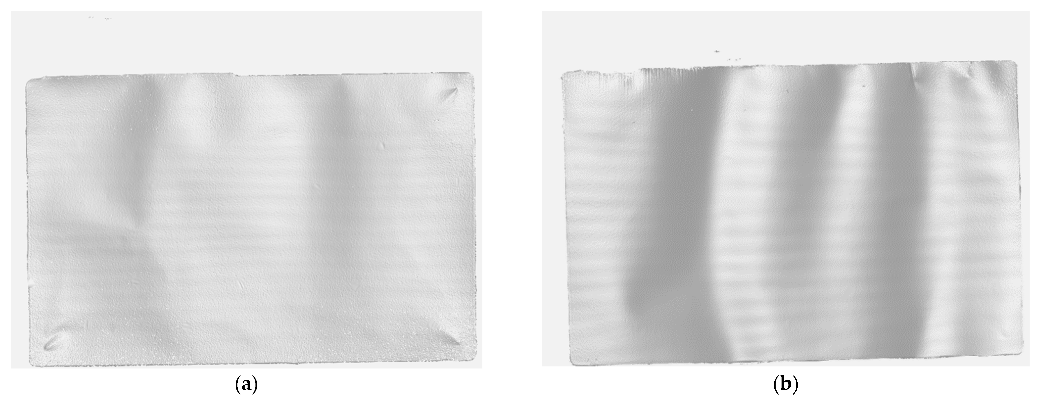
Particularly in the case of high electrode compression, various mechanical effects occur in the calendering process. Foil embossing is observed on the uncoated collector edge as wrinkles in the running direction form at a specific angle. The lengthening of the coated part of the electrode leads to the so-called saber effect, also known as camber or banana effect. The curvature occurs after slitting or during the calendering of asymmetric electrodes. Electrode corrugation appears as periodic waviness in the running direction over the entire web width. Corrugations at the coating edge are small waves located on the transition area of the coating and collector, which are caused by the edge effect occurring during coating [9,10].
Günther et al. evaluated the further processability of the electrodes qualitatively, with regard to the subsequent processes. However, no quantifications were made [10].
Regarding the separation of the electrodes into sheets, it is still not clear which effects from the calendering process occur regarding the geometrical properties of the sheets, which highly affect the subsequent stacking process. Mayer and Fleischer carried out a theoretical impact analysis for this purpose, wherein the influence of calendering and singulation on the individual single sheets was investigated [11]. Furthermore, a methodology to draw conclusions on the resulting stacking accuracy, based on the shape of the single sheets, was outlined [11]. Despite the lack of quantitative studies, the shape of the single electrode sheets has a massive impact on the achieved stacking accuracy after the stacking process.
To sum up, on the one hand, the process chain from calendering to separation has an important influence on cell performance in general; on the other hand, there is a strong dependence on subsequent production processes. In addition, the investigation of mechanical properties in the processing of electrodes is still hardly quantified in the literature. For this reason, the effects of strong compaction during calendering on the electrodes, as well as on the individual single sheets after separation, will be investigated in this paper.

2. Materials and Methods

The relationships between different densities, the characteristics of geometric behavior, and the impact on the separation process are investigated. To be able to formulate statements independent of the type of material, two different materials are chosen. The idea is not to compare the two different active materials used on the anode and cathode sides but to see the difference between single- and double-sided coated electrodes. Since there was no single-sided coated NMC811-material available, the investigations were conducted with a NMC811 cathode (double-sided coating) and a hard carbon anode (single-sided coating). It is assumed that the general mechanical behaviors are comparable because the active material particles show the same morphology. Both have spherical particles.
The NMC811 cathode was manufactured uncalendared by Enertech International, containing 94% active material, 3% carbon black and 3% binder. The surface loading of the coating is 20.8 mg/cm2, which is applied symmetrically on both sides of a 15 µm-thick aluminum foil. The coating width is 155 mm, on a 215 mm-wide aluminum foil.
The hard carbon anode was manufactured at the Karlsruhe Institute of Technology (KIT). The water-based slurry contained 93% of spherical-shaped hard carbon particles (BHC-240, Shandong Gelon LIB Co., Ltd., Linyi, Shandong, China) with a diameter of about 10 µm (D50), 1.4% carbon black and 5.6% of the binder system, CMC/SBR. The slurry was coated, single-sided, on a 200 mm-wide and 20 µm-thick aluminum foil with a coating width of 150 mm [12].
For the calendering process, the experiments were investigated with the calender from KIT, built by Saueressig. The calendering machine has rollers with a diameter of 700 mm and a width of 500 mm that can be tempered up to 90 °C. The maximum possible line load is 2000 N/mm, while the maximum web speed is 30 m/min.
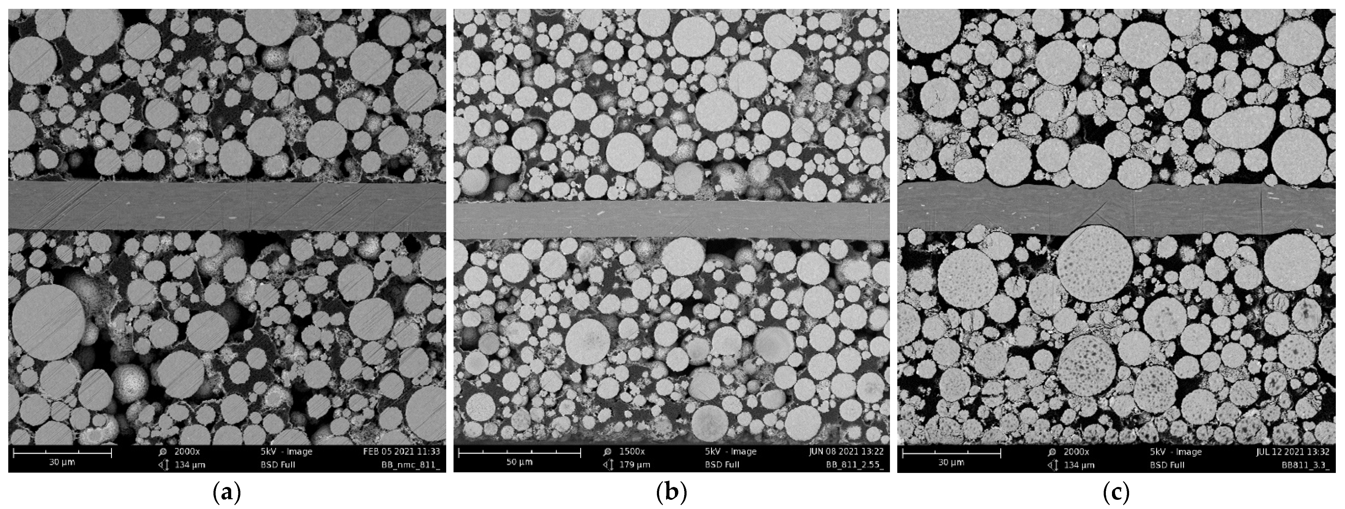
Cross-sections of uncalendared and calendered NMC811 electrodes were made with an argon ion cutter, EM TIC 3X (Leica Microsystems GmbH, Wetzlar, Germany). Scanning electron microscopy (SEM) images were obtained using a Phenom ProX (Thermo Fisher Scientific, Waltham, MA, USA).
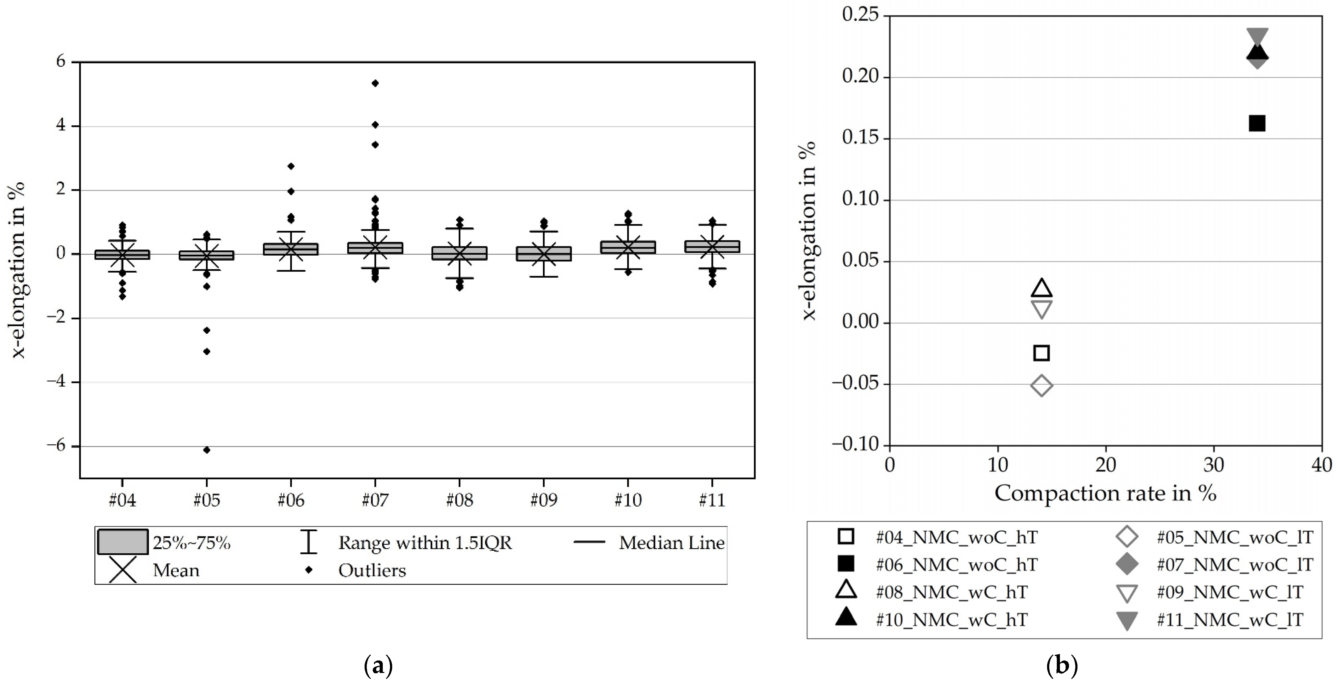
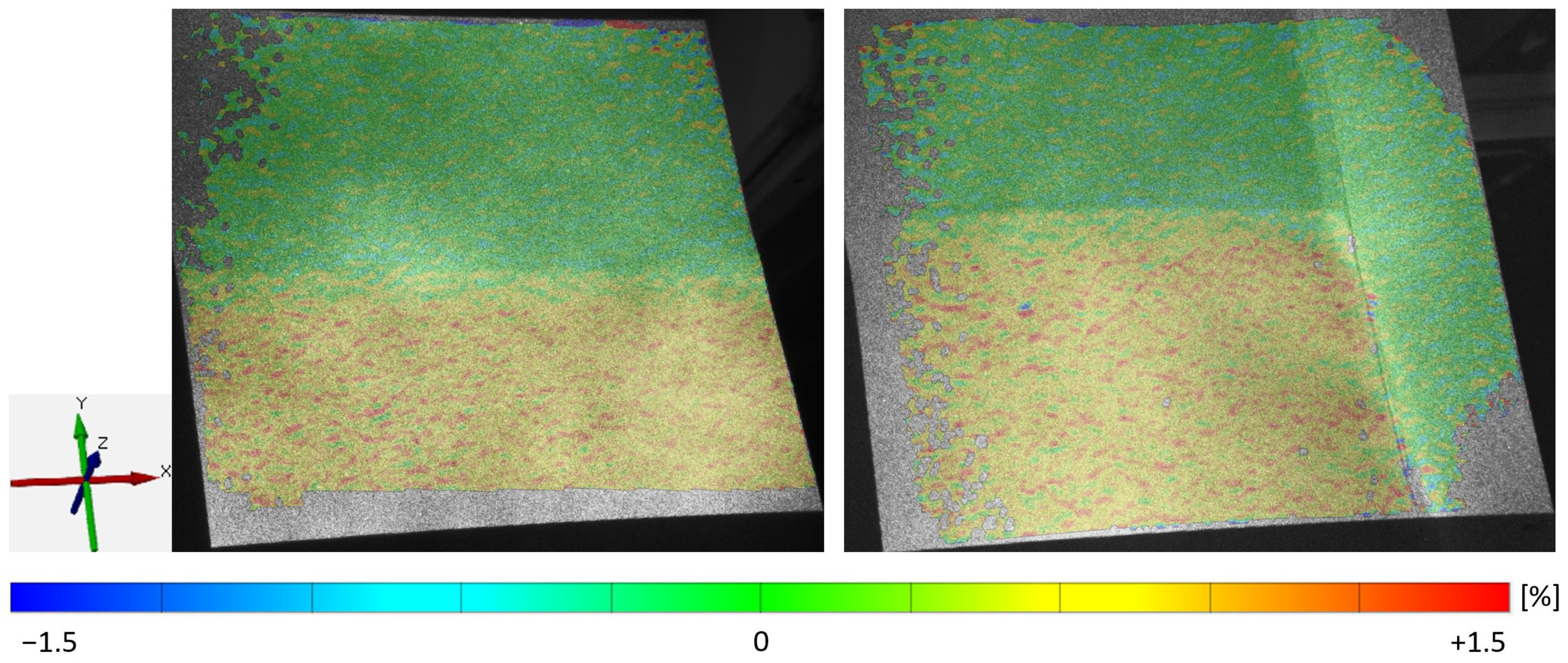
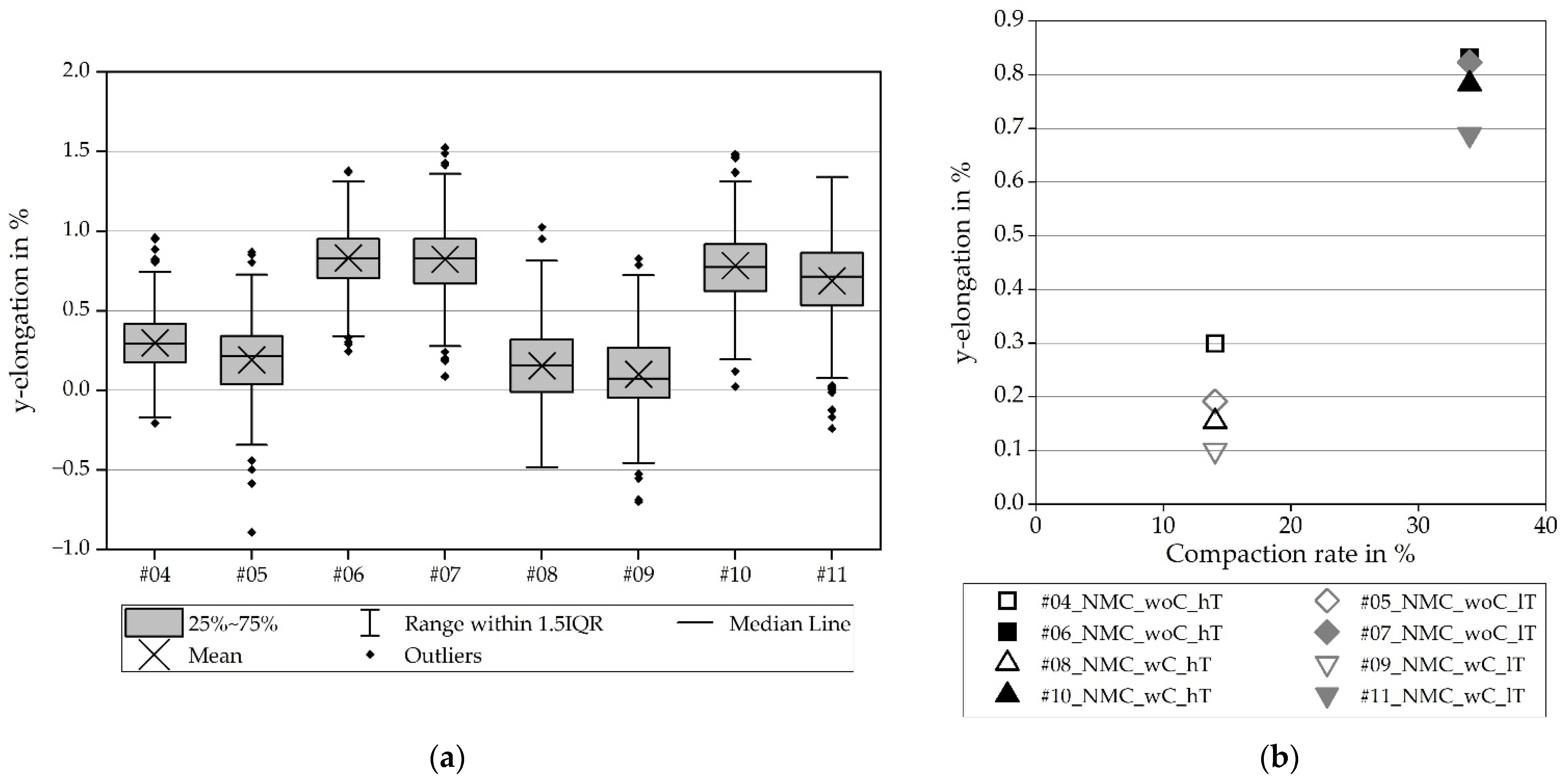
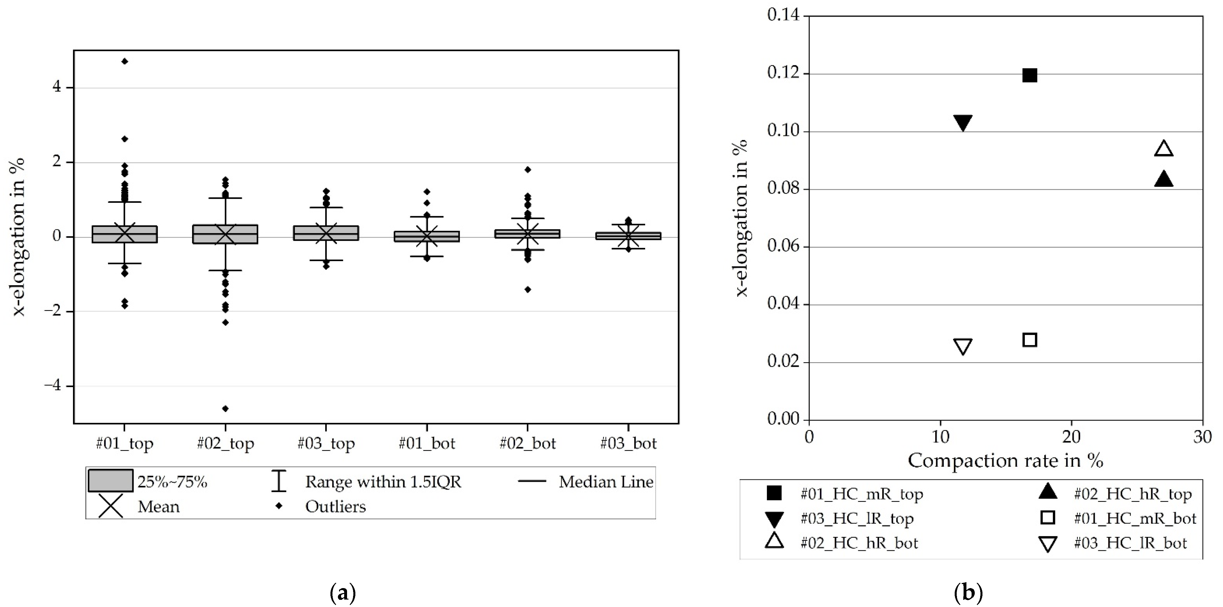
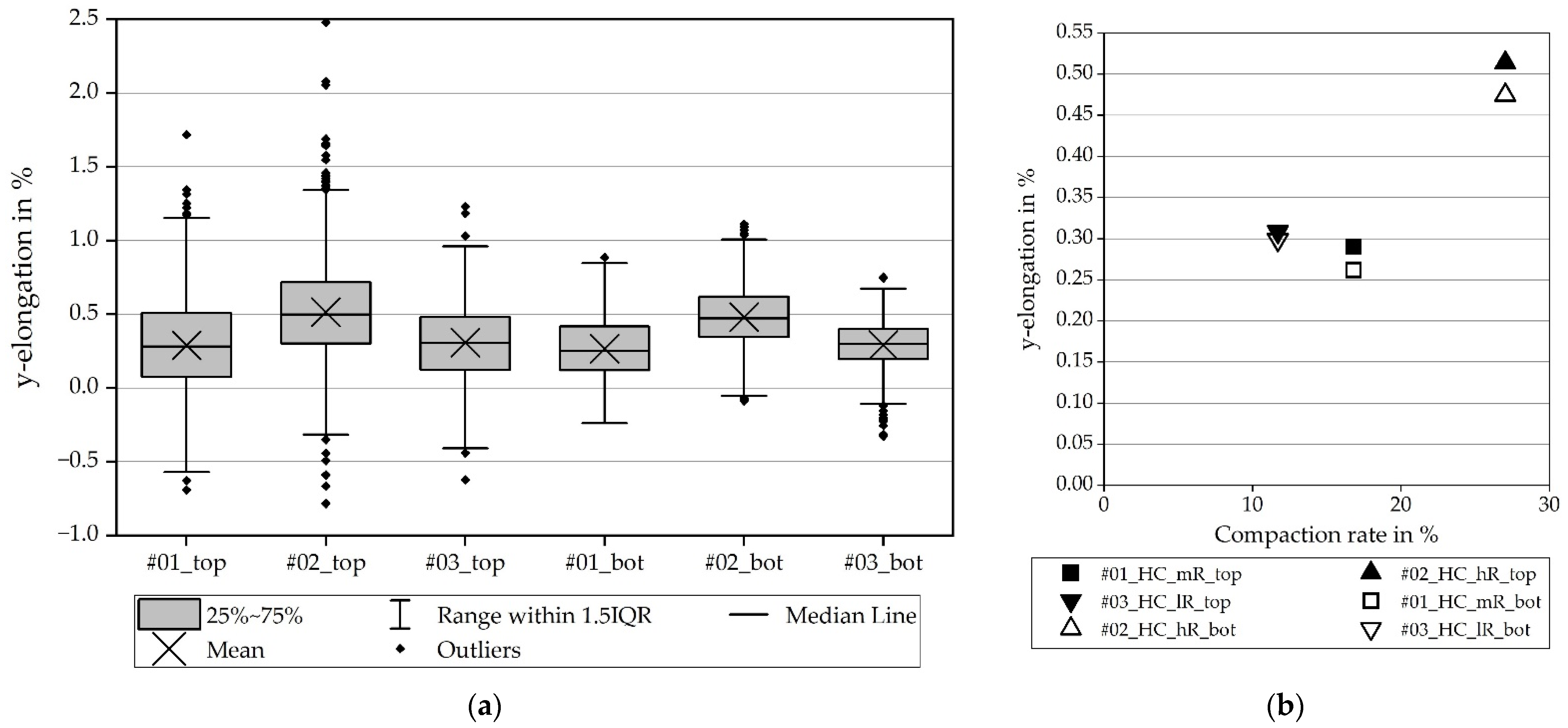
To be able to determine the influence of the calendering process on the subsequent process steps, the results are evaluated using the introduced elongations and resulting geometric formations. The detection of the elongation of the electrode surface due to calendering is performed with an optical 3D coordinate measurement machine, an ATOS Core 135 (GOM GmbH, Braunschweig, Germany) [
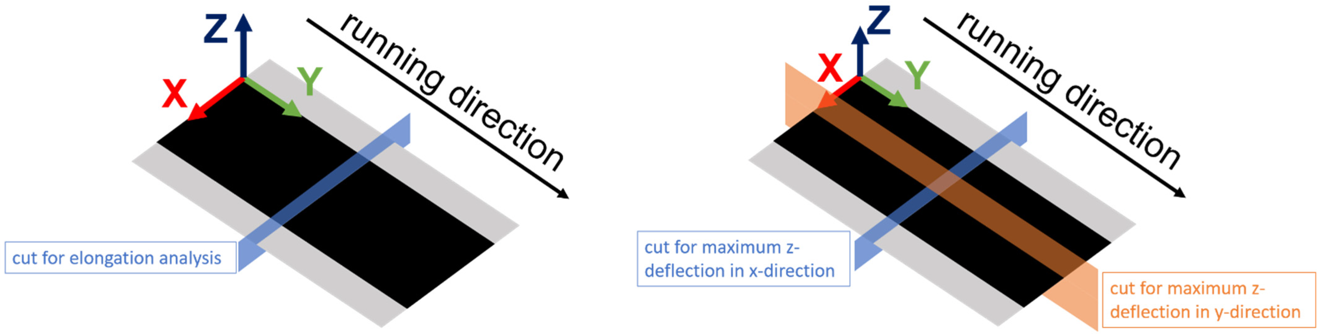
13]. To achieve this, a random color pattern is sprayed onto the electrode surface and two pictures are taken. One is taken before and one directly after calendering so that the deviations between the color dots can be measured and the integrated software can calculate the elongation. The calculated elongation comprises the x and y parts. The x-elongation is evaluated in the x-direction, which is defined as being crosswise to the running direction (see 
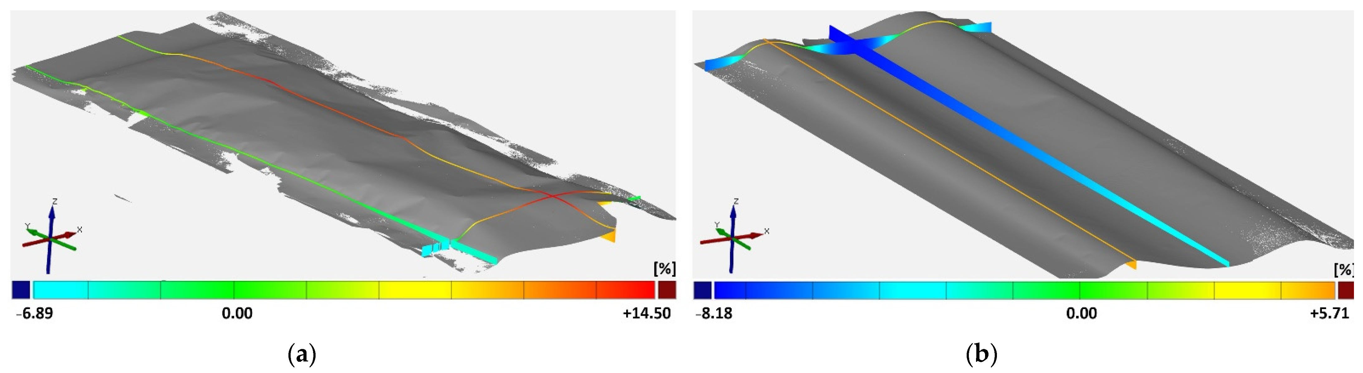
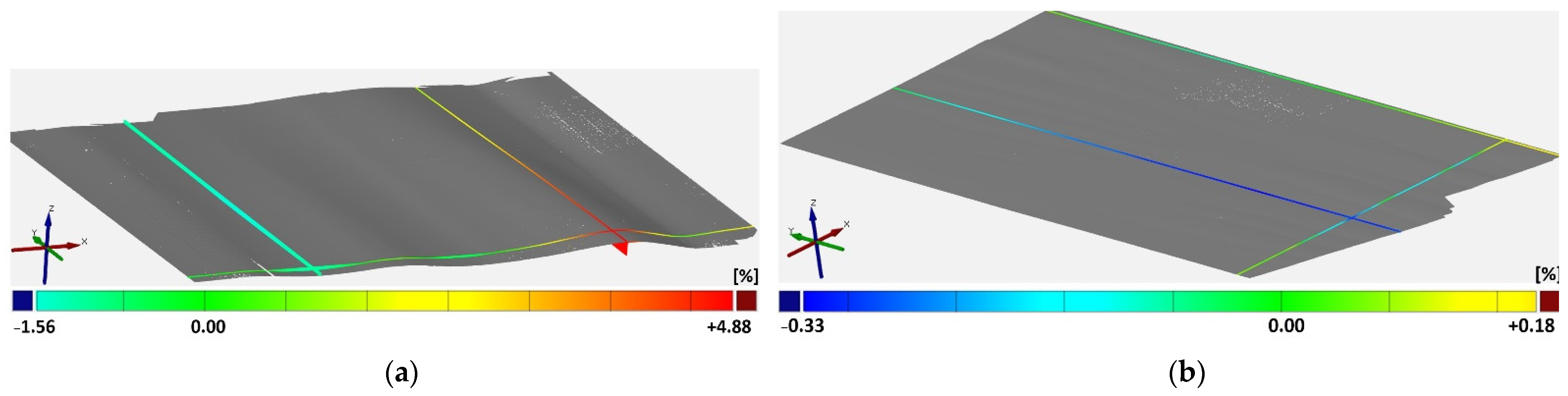
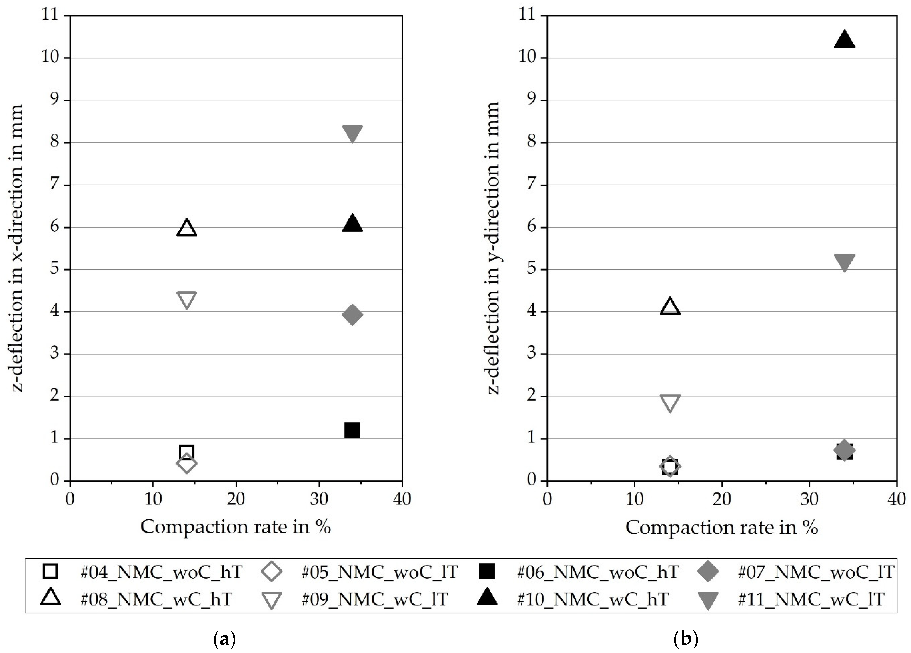
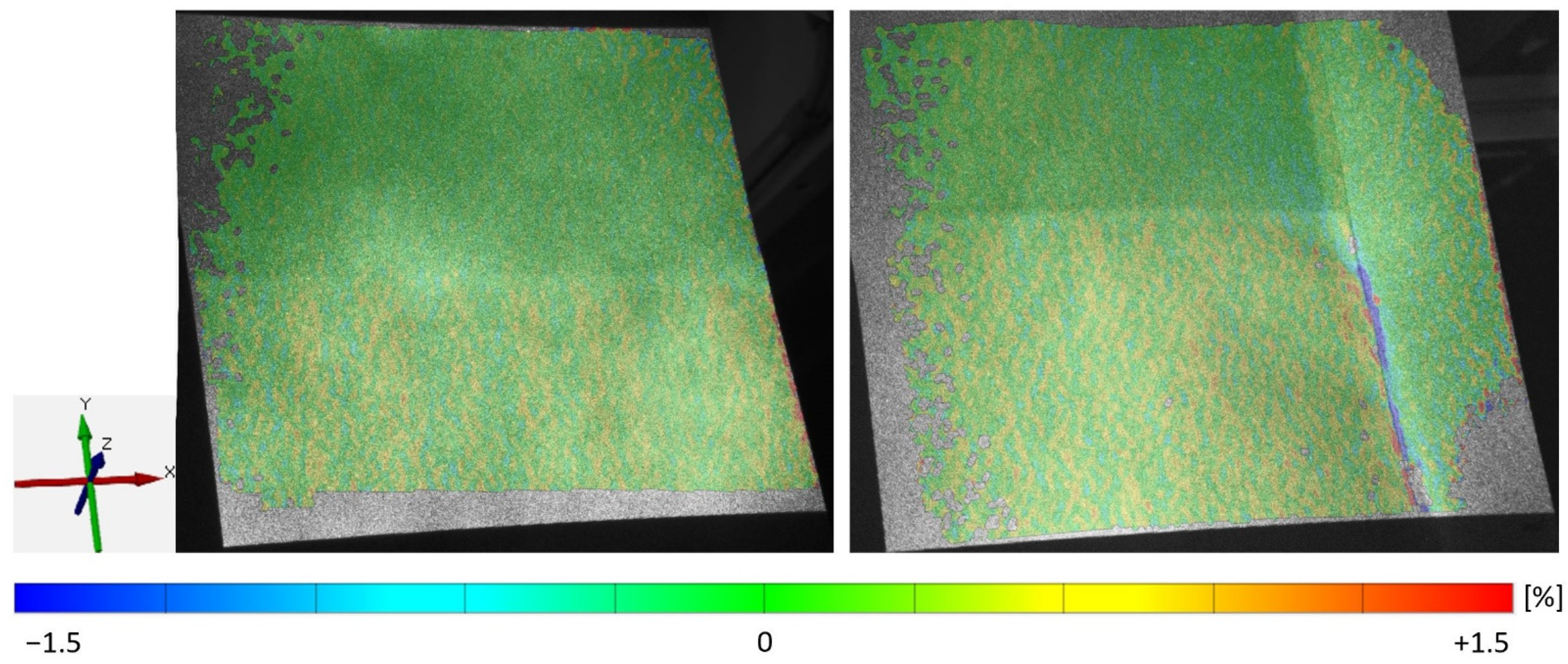
Figure 1). Analogously, the y-elongation is evaluated in the y-direction; that is, in the running direction. Furthermore, for the purposes of this study, 3D scans of the surface of the electrode were processed for the investigation of deformations. The maximum absolute deflections in the z-direction, perpendicular to the web in the x-direction (crosswise to the running direction), and in the y-direction (in running direction) were analyzed for the 3D scans.
To compare the present results with other research papers, density is considered a common material property. The density was calculated using the thickness and the weight of electrode samples (exclusive of the collector foil). For the measurement of electrode thickness, the digital indicator MarCator 1075R (Mahr GmbH, Goettingen, Germany) was used [14,15]. The weight of the electrode samples was measured with the laboratory balance EW 220-3NM (KERN & SOHN GmbH, Balingen-Frommern, Germany) [16].
Separation into single-sheet electrodes was carried out by means of a strip steel-cutting device in the laboratory at KIT, which was built by the Manz company. For this purpose, strips of about 25 cm were cut from the calendered electrode coil. These were placed under the steel strip tool, which punched out the shape from the underlying electrode using compressed air. The sheet size is ~200 mm × 135 mm. To evaluate the geometric shape of the single-sheet electrodes, the above-described optical 3D coordinate measurement machine, an ATOS Core 135 (GOM GmbH, Braunschweig, Germany), was used. The single-sheet electrodes were placed on a flat table and the shape, including absolute deflections in the z-direction, was recorded. In order to assess the geometric shape, contour lines were evaluated in the machine direction at intervals of 10 mm. These were averaged with each other to obtain an averaged curve for the elevation profile of the sheet.
To increase the overall understanding from the generated material parameters to the impact on the processes themselves and the resulting electrochemical properties, the cathode material was analyzed in the coin cells.
For electrochemical measurements, coin cells were assembled in a half-cell setup (NMC811 cathode vs. lithium metal anode). Therefore, CR2032 cells from the MTI Corporation, purchased through PI-KEM, were used as cell housing materials, lithium chips were purchased from PI-KEM, along with a glass-fiber GFD separator from VWR and electrolyte from Gotion (1M LiPF6 in EC/DMC + 3 wt % VC).
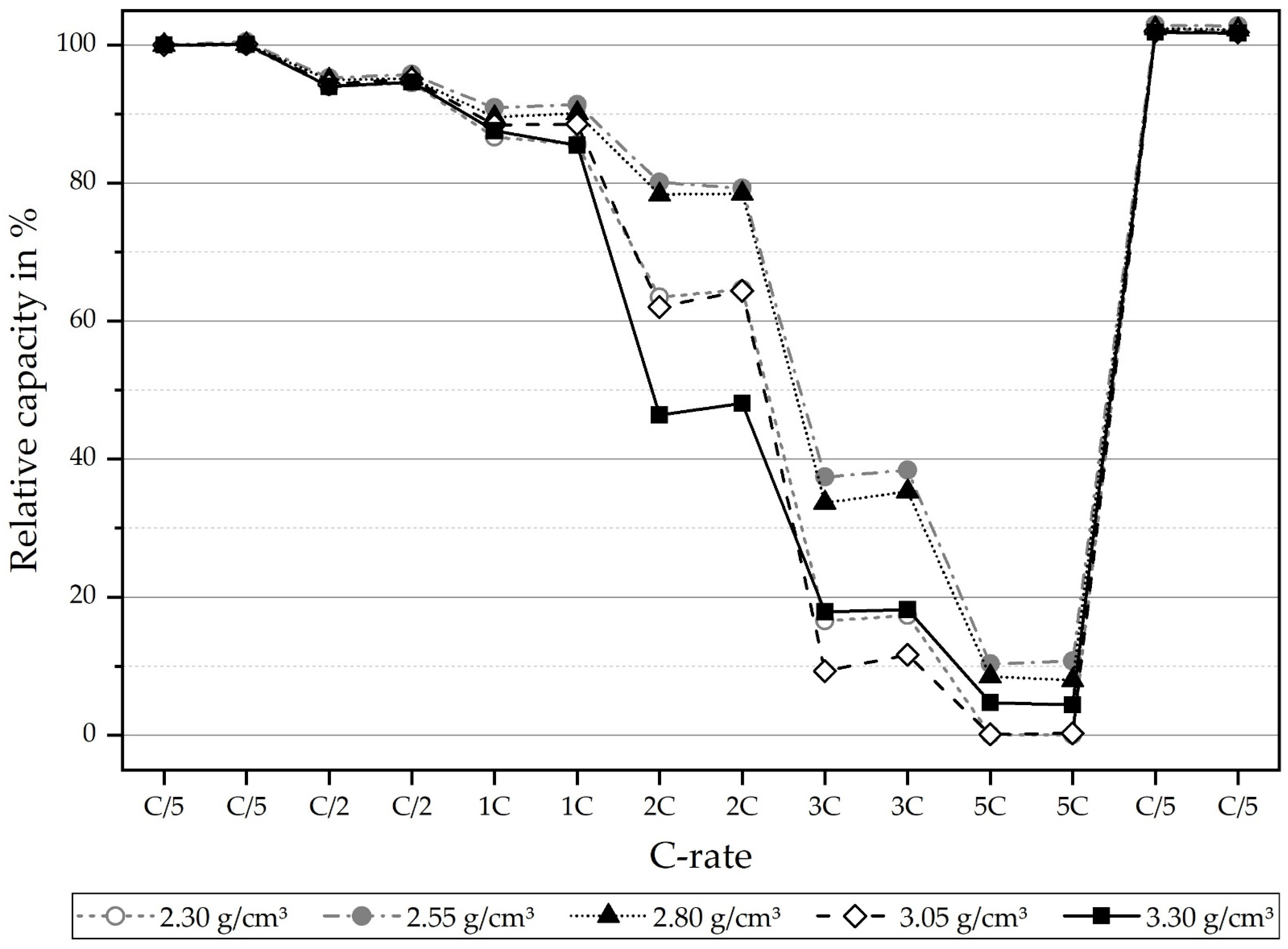
The NMC811 cathodes were punched into 12 mm-diameter disks; for the lithium anode, 15.8 mm-diameter disks were used, and the glass fiber separator was cut into 17 mm-diameter circles. The cathodes and separators were dried under reduced pressure at 130 °C and 180 °C, respectively, before cell assembly. The cells were assembled in an Ar-filled glovebox and filled with 350 µL of electrolyte to allow for sufficient wetting. For each calendering condition (2.30, 2.55, 2.80, 3.05 and 3.30 g/cm3), two coin cells were built to enable replication of the results.
The coin cells were tested using a BioLogic VMP3 potentiostat. For setting the C-rate, the capacity of the cathode was practically determined in a pre-test, starting with a theoretical capacity from the datasheet of 4.4 mAh/cm2. By applying a current of C/20 (I = 0.22 mA) for charge and discharge (3.0–4.3 V), practically, 3.9 mAh/cm2 was determined and this capacity was used for all subsequent formation and rate tests (1C = 3.9 mA/cm2 cathode or 4.4 mA/cm2 coin cell). All cells were formatted by cycling three cycles at C/10 (charge with CC C/10 and CV at 4.3 V until I < C/20; discharge at C/10 CC); the voltage range was 3.0–4.3 V. Then, an antisymmetric rate test was performed with the same charge current of C/5 CC, including a CV phase at 4.3 V until I < C/20. The discharge rate was varied after each set of two full cycles (C/5, C/2, 1C, C/5, 2C, 3C, 5C, C/5).

3. Results

The findings have been divided into the results of the cell tests, the observations on calendering regarding the elongations occurring in the coating and substrate, as well as the change of the geometric shape of the web. Lastly, mechanical studies on singulation are presented.

3.1. Cell Tests

To test the electrochemical performance of the NMC811 cathodes, electrode samples with different densifications (2.30, 2.55, 2.80, 3.05 and 3.30 g/cm3) upon calendering were built into coin-type cells in a half-cell configuration (NMC811 vs. lithium metal), using 1 M LiPF6 in EC/DMC + 3 wt % VC as the electrolyte. Cells were formatted by applying three cycles, with a C-rate of C/10. The practical discharge capacity of the cathodes after formation at C/10 was measured at 3.85 mAh/cm2 for densities of 2.30, 2.55 and 3.30 g/cm3. For 2.80 and 3.05 g/cm3, the capacities were slightly higher, at 3.90 mAh/cm2. For slow C-rates of C/10, equaling a current density of 0.39 mA/cm2, the practical discharge capacities at different grades of densification are very similar. To check whether the degree of density has an influence on power performance, an asymmetric rate test was subsequently performed on all cells, meaning that charging was performed at a C-rate of C/5 CC, with a CV phase at 4.3 V (until I < C/20) and rates in the discharge direction were varied from C/5 to 5C. To check for degradation due to the rate testing, C/5 discharge was also built into the test plan at the end of the test procedure. For each C-rate, two full cycles were applied. Figure 2 shows the results of the C-rate performance test. Clearly, it can be seen that the degree of densification only plays a minor role in slow C-rates, such as C/5 (=0.78 mA/cm2) and C/2 (=1.95 mA/cm2). However, in the case of high-power performance, the degree of densification significantly influences the capability of retaining high capacities, due to the decrease in contact resistance and, therefore, a smaller drop of the overpotential. In the case of the 1C (=3.9 mA/cm2) discharge rate, there are differences of up to 5% in discharge capacity retention, depending on the degree of calendering. For 2C (7.8 mA/cm2) and 3C (11.7 mA/cm2), this is even more significant (25–30%). At the highest C-rate of 5C (=19.5 mA/cm2), only very little capacity was achieved for all cells. It is important to note that, due to the high Ohmic resistance of coin cells, the absolute differences in capacity retention for high C-rates are somewhat skewed because of the high internal overpotentials of the cell components themselves. This means that in practical application, where electrodes are assembled in round cells or, even better, in prismatic or pouch-type cells with much lower internal resistance, it could be very much possible to allow for higher absolute capacity retentions at such high C-rates (e.g., 5C). However, since the conditions for the differently calendered cathodes are all the same for the coin cell tests, the trend that is found here for each individual C-rate gives significant insight into the ideal densification for performance. It was found that, from all named densification grades, 2.55 g/cm3 allows for the highest power performance of all tested C-rates. This performance is closely followed by those electrodes densified to 2.80 g/cm3. On the other hand, lower densified and higher densified electrodes (2.30 g/cm3 and 3.05 g/cm3, respectively) perform worse for all tested C-rates. Much higher densification of 3.30 g/cm3 shows the lowest performance, up to a C-rate of 2C; surprisingly, however, in terms of much higher C-rates (3C–5C), there seems to be some advantage in terms of capacity retention compared to too-low densification. One possible explanation could be that the advantage of significantly increased electrode resistance, due to very high densification, outweighs the decreased porosity and, with that, less available contact of electrolyte to the active material. This conclusion can be supported by Figure 3, in which the SEM images for the uncalendered electrode and two calendering rates are shown. For a density of 2.55 g/cm3, the particles are in contact with each other. The highest density of 3.55 g/cm3 leads to cracked and deformed active material particles.

3.2. Investigations on Calendering

The cell performance tests show an optimal density of 2.55 g/cm3. This correlates to the low compaction of 14.06% established for the NMC811 cathodes. The high compaction of 34.03% matches a density of 3.3 g/cm3 for NMC811. The experiments were performed with the optimal density found from thethe coin cell tests. Additionally, higher densities are investigated in calendering and singulation despite a poorer cell performance, since there are efforts to process higher densities during calendering (see [8]). The investigations for the calendering of the electrodes are summarized in Table 1.
The experiments differ from the used materials, while both particles are spherical. Furthermore, different densities are achieved. In the diagrams, the density is represented by the compaction rate. The calender rollers have a temperature of 90 °C and the machine parameter web tension is set variably, as noted in the table above, by high (hT) and low (lT) tension. Besides this, the compaction rate is indicated by high (hR), medium (mR) and low (lR).
Figure 4 shows the general relationship for calendering, the finding that higher compaction requires higher line loads. The relationship for achieving a higher density seems to be similar for both materials. Because of that, it is assumed that the particle shape has a major influence on material behavior in the calendering process, independent of processing an anode or cathode material. The deviations of the line load, at 19–76 N/mm (in contrast to the high line loads of up to 2229 N/mm), are very low, so the fluctuations themselves have no significant impact on the results.
One important aspect of evaluating the influence of the calendering process on singulation is the geometric shape. Figure 5 shows two phenomena for the single-sided coated hard carbon anode, both with collectors. The deflection is described via the z-axis, which is orientated orthogonally to the electrode plane. The left case shows a deflection in only one direction, like a bulge. The right sample shows deflections in both directions, with positive and negative z-values, and rather resembles corrugations orthogonal to the running direction. The two variations depend on the compaction rate and the coating modification. For a single-side coating, high compaction leads to a bulge, while a low density shows corrugations orthogonal to the running direction. The higher the compaction, the stronger the displacement of the particles in the coating and the resulting elongation. For a low compression, the electrode discovers an elongation, but the material behavior includes only a small plastic portion. For high compression, the displacements are larger; therefore, the stresses in between the particles and the binder lead to elastic-plastic changes with a higher plastic portion. For a single-sided coating, the effect only appears on one side so that the elongation of the surface leads to a bulge or to the corrugations. Since the more calendered material is more compacted, it is also inherently stiffer. As a result, the material curves upwards like a bulge. Since the less calendered material is also less stiff, it cannot maintain the bulge. In the middle of the web, the material then lowers due to its own weight, leading to corrugation. For a double-sided coating, the stresses are the same for both sides. Therefore, both low and high compactions lead to corrugations, with the only difference being in the plastic portion.
For the bulge, as well as for the corrugation, the evaluation is calculated by the maximum span of the z-values. This method does not allow for any conclusion of the geometrical shape.
Additionally, Figure 6 shows the deformation for a double-sided coated electrode with and without the uncoated collector area. The aim of this investigation is to evaluate the influence of the uncoated areas, which are not applied with force and, therefore, no stress is submitted. The samples show no corrugation or bulge formation for the homogeneous electrode without an uncoated collector. On the contrary, the electrode with uncoated collector areas shows deformations, which suggests that the coating is elongated by calendering. The uncoated collector, being not applied with force, is not influenced. Hence, deformations are built in the coating area. As the uncoated part holds back the border area between coated and uncoated part corrugations in and orthogonal to the running direction are formed. In particular, corrugations in the running direction are seen for both compaction rates with NMC811 but were not recorded with GOM. This effect is also described in [10].
Figure 7 describes the deformation of the electrodes by the z-deflection, while the values are calculated by a profile orthogonal to the running direction in (a) and along the running direction in (b). First of all, a distinction is made between the deformations for electrodes with and without an uncoated collector. As mentioned above, the uncoated area limits the degree of freedom for the coated part in the running direction; therefore, corrugations and bulges are formed strongly. Secondly, independently, with or without a collector, there is a difference between low and high compaction. Higher compaction leads to higher stresses and deformations. In contrast to the compaction, the web tension has no visible influence on the geometrical formation.
The uncoated collector influences the nearby coated area. As shown in Figure 8, on the right side, a clear blue line of negative elongations shows the stopping point of the lateral flow of the coating. In contrast, the x-elongation of the electrode without a collector (No. 7) sums at the right edge as a red line of high deformation. In both cases, a slightly striped pattern is visible in the y-direction, which also confirms the prevention of unhindered expansion in the x-direction.
The boxplots for Figure 9a are generated via the evaluated elongation of a profile through the calendered section of the respective experiment (here as a representation No. 7 and 11) in the x-direction. For a well-arranged overview, only the average elongations of the experiments are depicted in Figure 9b. These average values show slightly bigger x-elongations on the calendered electrodes with a collector.
In contrast, Figure 10 and Figure 11 show that the y-elongation of the electrodes without a collector is slightly bigger because of the presence of the aluminum substrate foil, which can be elongated in a y-direction. On the contrary, the electrode with a collector is hindered by the unstressed collector (as seen in Figure 10, right, as the green area of nearly zero elongation). Furthermore, the elongations in the y-direction are up to four times higher than those in the x-direction.
Finally, it is of further interest whether the elongation applied to the electrode affected the coating exclusively. Figure 12 shows the x-elongation in the x-direction for the hard carbon anode. This is differentiated between the coating surface (_top) and the bottom side, which, in this case, is the aluminum foil (_bot). The x-elongation in the hard carbon coating is comparable to the x-elongation in the NMC811 coating. One explanation could be that due to similar spherical particle morphology, the interaction between the coating and the substrate occurs in a similar manner. The findings concerning the elongations in the aluminum foil are therefore transferable. The mean values of the x-elongations differ only by hundredths or less and lie in the same scatter ranges as the other ones. As a result, there is no significant influence of the compaction rate on the amount of x-elongation that was measurable. Nevertheless, the current collector foil below the coating is exposed to elongation.
Figure 13 depicts the elongation in the y-direction of the hard carbon coating and the collector foil on the bottom. The y-elongations in the hard carbon coating are in the range of the y-elongations in the NMC811 coating. It is therefore assumed that these results for the hard carbon are also transferable to NMC811. The average values for low and medium compaction differ by less than the hundredths and lie in the same scatter range. As the y-elongation for the high compaction rate is clearly higher, a tendency toward a direct correlation between the compaction and the y-elongation is visible.
All in all, the scattering of the elongation is higher for the coating in both x- and y-elongation. This is a result of the inhomogeneous coating, compared to the blank foil. The scatter on the foil is credited to the measuring system. High compaction rates seem to result in high y-elongations and the aluminum current collector foil below the coating is almost as stressed as the coating itself.

3.3. Investigations on Singulation

To investigate the geometric shapes of the single sheets after calendering, experiments No. 8 and No. 10 from Table 1 were further examined. The reason for the selection was that the hard carbon anode material is coated on one side. After separation, the material curves into a cylinder, which makes further automated processing impossible. Among the double-sided coatings, the most corrugated electrode was selected as being experiment No. 10. Experiment No. 8 was also added, using the optimum compaction rate. In addition, only those electrodes with collectors were further investigated since less z-deflection was observed after calendering in those electrodes without collectors. To ensure comparability, experiments No. 8 and No. 10 were investigated using the same web tension. Since the geometric shape does not depend on the web tension, as investigated above, no further experiments were examined. From the electrode coils of experiment No. 8 and No. 10, respectively, 5 single-sheet electrodes were punched out by strip steel-cutting and their geometry was scanned with GOM.
Figure 14 shows an example of a recorded single-sheet electrode, from experiment No. 8, as well as that from No. 10.
With reference to Mayer and Fleischer [11], all single-sheet electrodes show corrugations that are pronounced in the running direction of the electrode. Localization of the remaining corrugations in only the area of the conductor tab and a smoothing of the electrode in the other part of the sheet, on the other hand, cannot be detected, as was suspected by Mayer and Fleischer [11]. This results from the fact that the material has been plastically deformed by the calendering process and, furthermore, that it has become so stiff that it does not deform under its own weight. The edge corrugations that occur as a result of the edge effect in the coating can be slightly detected in some electrodes. However, no regularity can be identified. Furthermore, the corrugations that are orthogonal to the running direction, which were observed during the calendering process, can no longer be detected. Thus, it is assumed that they do not propagate into the single-sheet electrode.
To investigate the average amplitude of the corrugations in the running direction, 14 contour lines were recorded from each scanned single-sheet electrode. The average of the z-values was formed to obtain one average contour line of each single sheet. The average of the 5 investigated sheets per parameter setting was then formed afterward. For experiments No. 8 and No. 10, the two resulting curves are shown in Figure 15.
It can be seen that the amplitudes of the corrugations are related to the compaction rate of calendering. This can be explained by the fact that stronger compaction causes the electrode to be elongated more, and by its interaction with the uncoated part of the collector foil. Furthermore, it can be seen from Figure 15 that the coil’s bending slightly superimposes the corrugation. The respective ends of the electrodes show that the core of the electrode coil was associated below the curves.

4. Discussion and Outlook

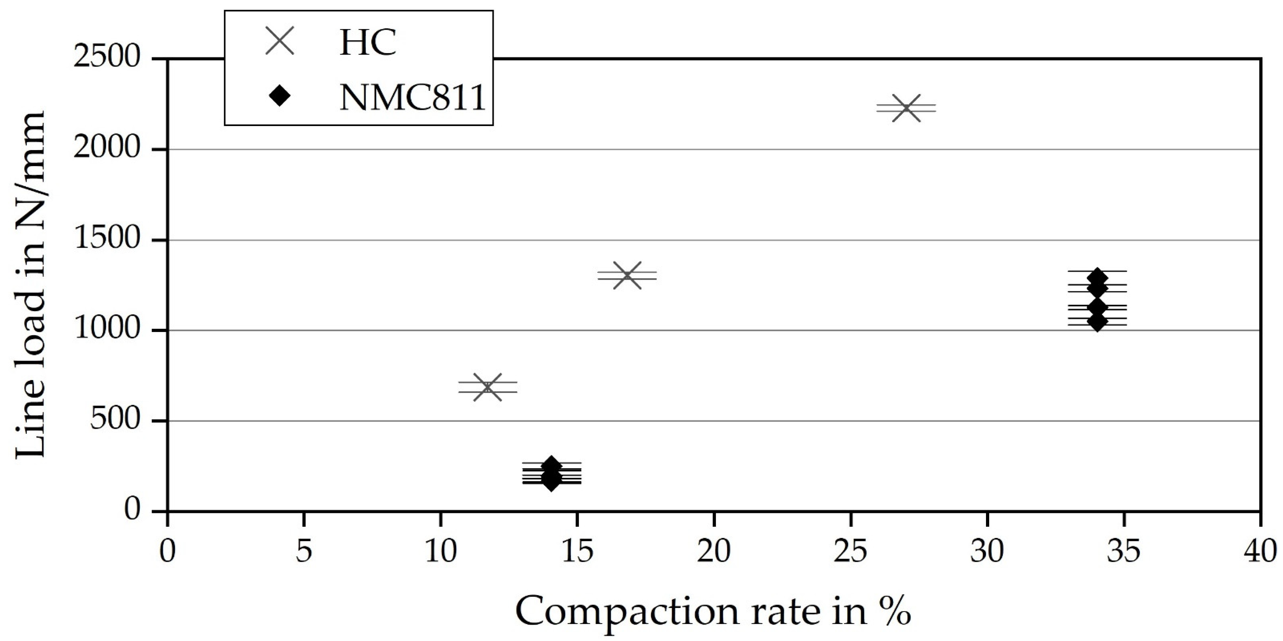
This paper demonstrates that the material’s behavior and its interaction with the machine have a significant influence on calendering and separation. An increasing compaction rate during calendering leads to stronger deflections of the electrodes. For single-sided coated electrodes, both corrugation and bulges occur, whereas double-sided coated electrodes only show corrugation. Electrodes without an uncoated current collector stay flat, up to small corrugations. Despite increasing the x- and y-elongations while increasing compaction rates, the electrode has no limitation in compensating displacement, due to the lack of an uncoated foil boundary. Web tension seemed to have no significant influence on the deflection. The influence of the material’s properties on the material’s behavior during processing is still not fully understood. For instance, the particle morphology, the type of substrate, or the calender roller diameter are parameters that are expected to have an impact on the processing results. Due to the remaining uncertainties, the above assumptions have to be verified and confirmed in further scientific work. Additionally, the impact of calendering on web guidance and winding also needs to be investigated as these are critical processes for the sensitive coating. Subsequently, during the slitting process, the stressed electrode may result in a saber effect that complicates or even precludes further processing.
In addition, this paper presents the influence of calendering on the separation process, with the resulting shape of single-sheet electrodes. The separation of the electrodes shows a strong dependence of the electrode shape on the compaction rate. Corrugations after calendering propagate into the single sheet. The higher the compaction rate, the greater the corrugations in the single-sheet electrode. However, it has not yet been investigated regarding up to which level of corrugation the tolerances of the subsequent processes, in particular the stacking process and its resulting stacking accuracy, can be maintained. One interesting approach is to simulate the stacking process, to quantify which z-deflections can be tolerated since these also occur at lower compaction rates. For this purpose, the presented paper can serve as input data, particularly in the form and amplitude of the corrugations, for a simulation that is presented, for example, in [11].
The paper provides a first quantification of the mechanical behavior of the electrodes, which might cause problems during further processing. However, the actual effects, especially regarding the fulfillment of tolerances in subsequent processes, are still barely investigated and require further research.

Author Contributions

Conceptualization, D.M., A.-K.W., B.B., J.B.; methodology, D.M., A.-K.W., B.B., J.B., A.S.; software, J.B., A.-K.W.; formal analysis, D.M., A.-K.W., B.B., J.B., A.S.; investigation, D.M. (Section 3.3), A.-K.W. (Section 3.2), B.B. (Section 3.2), J.B. (Section 3.2 and Section 3.3), A.S. (Section 3.1); resources, A.S., J.F.; writing—original draft preparation, D.M., A.-K.W., B.B., J.B., A.S.; writing—review and editing, J.F.; visualization, D.M., A.-K.W., B.B., J.B.; supervision, J.F.; project administration, J.F.; funding acquisition, J.F. All authors have read and agreed to the published version of the manuscript.

Funding

This research was funded by the Federal Ministry of Education and Research (BMBF), Project Sim4Pro (grant number 03XP0242C) and Deutsche Forschungsgemeinschaft (DFG, German Research Foundation) under Germany’s Excellence Strategy—EXC 2154—project number 390874152.

Institutional Review Board Statement

Not applicable.

Informed Consent Statement

Not applicable.

Acknowledgments

This work was done at the KIT Battery Technology Center (KIT-BATEC) and contributes to the research performed at CELEST (Center for Electrochemical Energy Storage Ulm-Karlsruhe). We acknowledge support by the KIT-Publication Fund of the Karlsruhe Institute of Technology.

Conflicts of Interest

The authors declare no conflict of interest. The funders had no role in the design of the study; in the collection, analyses, or interpretation of data; in the writing of the manuscript, or in the decision to publish the results.

References

  1. Haselrieder, W.; Westphal, B.; Bockholt, H.; Diener, A.; Höft, S.; Kwade, A. Measuring the coating adhesion strength of electrodes for lithium-ion batteries. Int. J. Adhes. Adhes. 2015, 60, 1–8. [Google Scholar] [CrossRef]
  2. Gupta, P.; Üçel, İ.B.; Gudmundson, P.; Olsson, E. Characterization of the Constitutive Behavior of a Cathode Active Layer in Lithium-Ion Batteries Using a Bending Test Method. Exp. Mech. 2020, 60, 847–860. [Google Scholar] [CrossRef]
  3. Haselrieder, W.; Ivanov, S.; Christen, D.K.; Bockholt, H.; Kwade, A. Impact of the Calendering Process on the Interfacial Structure and the Related Electrochemical Performance of Secondary Lithium-Ion Batteries. ECS Trans. 2013, 50, 59–70. [Google Scholar] [CrossRef]
  4. Billot, N.; Günther, T.; Schreiner, D.; Stahl, R.; Kranner, J.; Beyer, M.; Reinhart, G. Investigation of the Adhesion Strength along the Electrode Manufacturing Process for Improved Lithium-Ion Anodes. Energy Technol. 2020, 8, 1801136. [Google Scholar] [CrossRef]
  5. Zheng, H.; Tan, L.; Liu, G.; Song, X.; Battaglia, V.S. Calendering effects on the physical and electrochemical properties of Li[Ni1/3Mn1/3Co1/3]O2 cathode. J. Power Sources 2012, 208, 52–57. [Google Scholar] [CrossRef]
  6. Singh, M.; Kaiser, J.; Hahn, H. Effect of Porosity on the Thick Electrodes for High Energy Density Lithium Ion Batteries for Stationary Applications. Batteries 2016, 2, 35. [Google Scholar] [CrossRef] [Green Version]
  7. Kang, H.; Lim, C.; Li, T.; Fu, Y.; Yan, B.; Houston, N.; de Andrade, V.; de Carlo, F.; Zhu, L. Geometric and Electrochemical Characteristics of LiNi1/3Mn1/3Co1/3O2 Electrode with Different Calendering Conditions. Electrochim. Acta 2017, 232, 431–438. [Google Scholar] [CrossRef] [Green Version]
  8. Meyer, C.; Bockholt, H.; Haselrieder, W.; Kwade, A. Characterization of the calendering process for compaction of electrodes for lithium-ion batteries. J. Mater. Process. Technol. 2017, 249, 172–178. [Google Scholar] [CrossRef]
  9. Bold, B.; Fleischer, J. Kalandrieren von Elektroden für Li-Ionen-Batterien. Z. Wirtsch. Fabr. 2018, 113, 571–575. [Google Scholar] [CrossRef]
  10. Günther, T.; Schreiner, D.; Metkar, A.; Meyer, C.; Kwade, A.; Reinhart, G. Classification of Calendering-Induced Electrode Defects and Their Influence on Subsequent Processes of Lithium-Ion Battery Production. Energy Technol. 2020, 8, 1900026. [Google Scholar] [CrossRef]
  11. Mayer, D.; Fleischer, J. Concept for Modelling the Influence of Electrode Corrugation after Calendering on Stacking Accuracy in Battery Cell Production. In Proceedings of the 54th CIRP Conference on Manufacturing Systems, Athens, Greece, 12–14 May 2021. finally accepted but not yet published. [Google Scholar]
  12. Hofmann, J.; Wurba, A.-K.; Bold, B.; Maliha, S.; Schollmeyer, P.; Fleischer, J.; Klemens, J.; Scharfer, P.; Schabel, W. Investigation of Parameters Influencing the Producibility of Anodes for Sodium-Ion Battery Cells. In Production at the Leading Edge of Technology; Behrens, B.-A., Brosius, A., Hintze, W., Ihlenfeldt, S., Wulfsberg, J.P., Eds.; Springer: Berlin/Heidelberg, Germany, 2021; pp. 171–181. ISBN 978-3-662-62137-0. [Google Scholar]
  13. GOM GmbH. ATOS Core. Available online: https://www.gom.com/de-de/produkte/3d-scanning/atos-core?msclkid=18ba87efd148119f98d3e75580c1cd55#9461ee4f23f04a25ac142f3b19d20509 (accessed on 31 August 2021).
  14. Mahr GmbH. Marcator_1075_R_Betriebsanleitung 2021. Available online: https://www.mahr.de/scripts/relocateFile.php?ContentID=190851&NodeID=22258&FileID=15047&ContentDataID=260126&save=0&isBlog=0 (accessed on 5 November 2021).
  15. Mahr GmbH. Available online: https://metrology.mahr.com/fileadmin/assets/files/MarCator--1075%20R--3759777--BA--DE-EN-FR-IT--2017-08-04.pdf:31.08.2021 (accessed on 31 August 2021).
  16. KERN & SOHN GmbH. Available online: https://dok.kern-sohn.com/manuals/files/German/eg-ew-ba-d-2130.pdf (accessed on 31 August 2021).
Figure 1. The coordinate system for GOM elongation (left) and deflection (right) analysis.
Processes 09 02009 g001
Figure 2. C-rate capability (relative capacity retention) of NMC811 cathodes with varying degrees of densification, tested in a half-cell configuration.
Processes 09 02009 g002
Figure 3. SEM cut of NMC811 cathode (a) uncalendered—2000× magnification, (b) calendered, 2.55 g/cm3—1500× magnification, (c) calendered, 3.3 g/cm3—2000× magnification.
Processes 09 02009 g003
Figure 4. Material behavior regarding compactability at different line loads.
Processes 09 02009 g004
Figure 5. The geometric shape of calendered hard carbon (single-sided): (a) sample No. 2 maximum compaction rate; (b) sample No. 3 low compaction rate.
Processes 09 02009 g005
Figure 6. Geometric shape of calendered NMC811 (double-sided, low compaction rate): (a) with an uncoated collector (No. 8); (b) without an uncoated collector (No. 5).
Processes 09 02009 g006
Figure 7. The z-deflection in: (a) x-direction; (b) y-direction.
Processes 09 02009 g007
Figure 8. Experiments No. 7 and 11: influence on x-elongation by the uncalendered area (top half) and the uncoated collector (right edge).
Processes 09 02009 g008
Figure 9. Elongation in the x-direction for NMC811: (a) all values including the scatter; (b) average values.
Processes 09 02009 g009
Figure 10. Experiment No. 7 and 11: Influence on the y-elongation by the uncalendered area (top half) and the uncoated collector (right edge).
Processes 09 02009 g010
Figure 11. Elongation in the y-direction for NMC811: (a) all values including the scatter; (b) average values.
Processes 09 02009 g011
Figure 12. Elongation in x-direction for the hard carbon anode, coating (_top) and current collector foil (_bot): (a) elongation with scatter; (b) average values.
Processes 09 02009 g012
Figure 13. Elongation in y-direction for the hard carbon anode, coating ( _top) and current collector foil (_bot): (a) elongation with scatter (b) average values.
Processes 09 02009 g013
Figure 14. (a) Exemplary scan of an electrode from experiment No. 8, with conductor tab on the top left; (b) exemplary scan of an electrode from experiment No. 10, conductor tab is on the top left.
Processes 09 02009 g014
Figure 15. (a) Exemplary single electrode sheet, with contour lines across the width of the electrode in the running direction; (b) summarized contour lines from experiments No. 8 and No. 10.
Processes 09 02009 g015
Table 1. Overview of the design of experiments.
No.MaterialDescriptionCompaction Rate in %Web Tension in NCollector C
1Hard Carbon HC#01_HC_mR16.8250with
2Hard Carbon HC#02_HC_hR27.0350with
3Hard Carbon HC#03_HC_lR11.7150with
4NMC811#04_NMC_woC_hT14.0680without
5NMC811#05_NMC_woC_lT14.061without
6NMC811#06_NMC_woC_hT34.0380without
7NMC811#07_NMC_woC_lT34.031without
8NMC811#08_NMC_wC_hT14.0680with
9NMC811#09_NMC_wC_lT14.061with
10NMC811#10_NMC_wC_hT34.0380with
11NMC811#11_NMC_wC_lT34.031with
Publisher’s Note: MDPI stays neutral with regard to jurisdictional claims in published maps and institutional affiliations.

