Ultrasonic Coupled Passive Wireless Oscillating Sensor System †


Laboratory of Electrical Instrumentation, Institute of Microsystems Engineering, University of Freiburg, Freiburg im Breisgau, 79085, Germany
*
Author to whom correspondence should be addressed.
†
Presented at the Eurosensors 2017 Conference, Paris, France, 3–6 September 2017.
Proceedings 2017, 1(4), 574; https://doi.org/10.3390/proceedings1040574
Published: 12 August 2017
(This article belongs to the Proceedings of Proceedings of Eurosensors 2017, Paris, France, 3–6 September 2017)
Abstract
:This paper presents, for the first time, an instrumentation technique for passively extracting a resonance frequency of a high-Q resonator across a wireless ultrasonic channel. As a first application, passive wireless measurement of temperature is presented along with a proof of concept of the wireless and passive operation of the device. Temperature resolution of 0.17 °C and a measurement range of 350 mm has been demonstrated.
1. Introduction
Passive wireless sensing is an instrumentation technique that allows analog wireless measurement of a transducer element [1]. In the age of internet of things, this technology has a fair chance of transforming from the current niches of harsh environment industrial sensing to the mainstream market [2]. Conventional wireless communication based on electromagnetic wave propagation is ineffective in situations where the sensor-node is in a conductive enclosure, such as a Faraday cage, thus techniques based on ultrasonic propagation have been lately proposed [3].
The work presented here is an attempt to investigate a chipless approach by matching a tuning fork resonator with an ultrasonic transducer. First the concept of wireless interrogation of high-Q resonators is discussed, followed by a description of the experiment that tests the following hypothesis: Can ultrasonic transducers and crystal resonators be used as passive wireless sensors? This is then followed by a characterization of the sensor element and subsequent analysis of its performance.
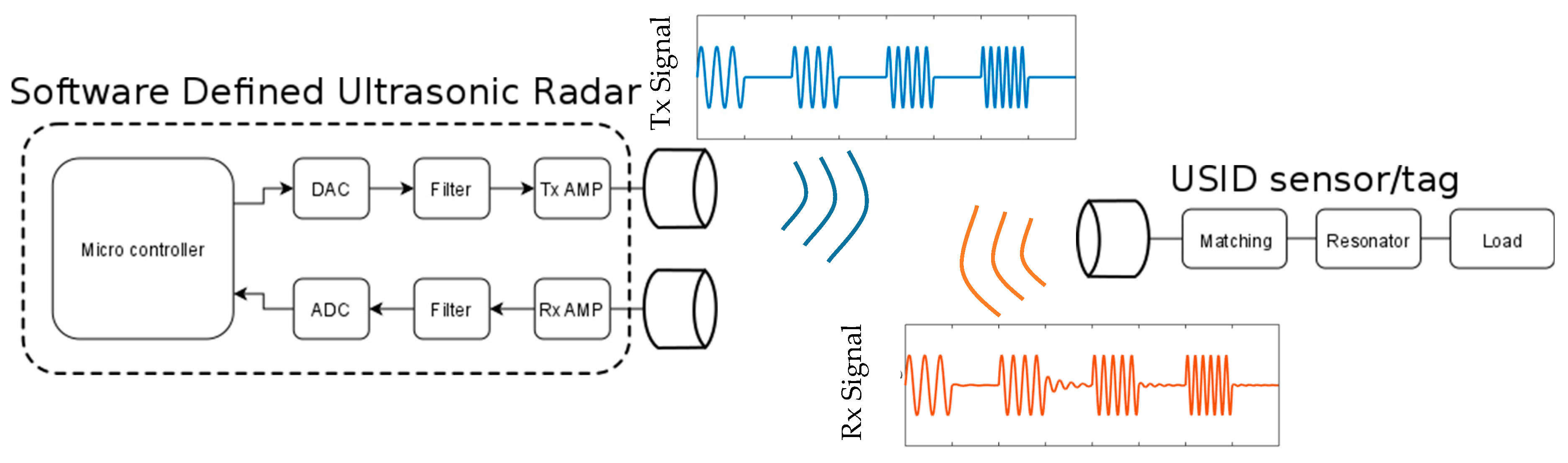
2. Concept for the Wireless Sensor System
Similar to wireless passive sensing using surface acoustic wave devices coupled to antennas [4], the approach presented here is based on a time domain separation of the transmitted and reflected signal. The wireless sensor system contains an excitation and receiving element with signal processing on the active part and a transceiver with an oscillating load on the passive sensor-node. The passive sensor-node consists of a resonator electrically connected to a radiating element, i.e., an ultrasonic transducer. Quality factor, the main figure of merit for a resonator in this application is defined as:
where is the resonance frequency, is the energy stored in the resonator and is the power dissipated. For resonators coupled with a radiating element, if the power dissipated to heat due to internal material and resistivity losses is low, the ringing time can be longer than environmental echoes, thus enabling a channel invariant measurement of the resonance frequency wirelessly.
External environmental factors like temperature influence material properties such as the stiffness tensor of a piezoelectric resonator. This causes a frequency shift of the resonant mode as explained by the harmonic perturbation theory. This effect can be used to measure temperature, passively over a wireless link and is demonstrated in Section 4.
3. Proof of Concept
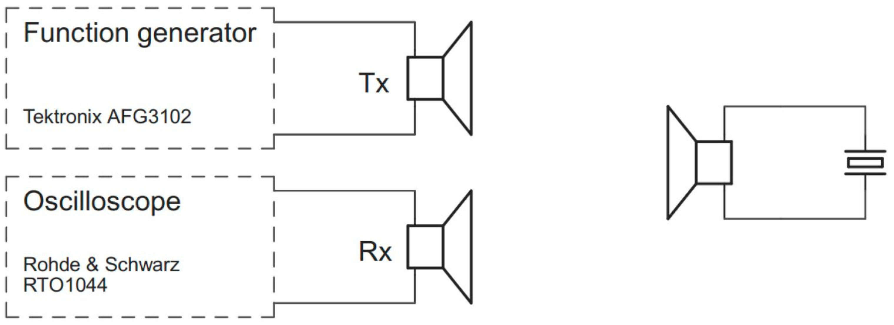
The main focus for the proof of concept lies on the passive extraction of a resonance frequency with wireless ultrasonic interrogation. Here, a temperature compensated quartz tuning fork resonator with a high-Q is used. A temperature sensing tuning fork resonator is presented later in this paper for the realization of the sensor system. The instrumentation setup is shown in Figure 2. The commercially available electronic components have a center frequency of 40 kHz and have been analyzed using a high precision impedance measurement.
A pulse width of 0.5 s is applied to the transmitter which results in a bandwidth of 2.4 Hz around the resonance. This causes the ringing of the high-Q resonator which allows for a time domain separation of Tx and Rx.
Figure 3 presents the measured time domain signal on the ultrasonic receiver. The excitation frequency decays after the burst in less than 2 ms and the high-Q resonator starts ringing in his resonance frequency. The shift of frequency from the excitation to the resonance frequency proofs the presented concept.
A backscattered signal could be measured with a channel power of −36 dBmV over a distance of 350 mm with 100 ms burst at 2 Vpp with and SNR of 10 dB.
4. Sensor Characterization
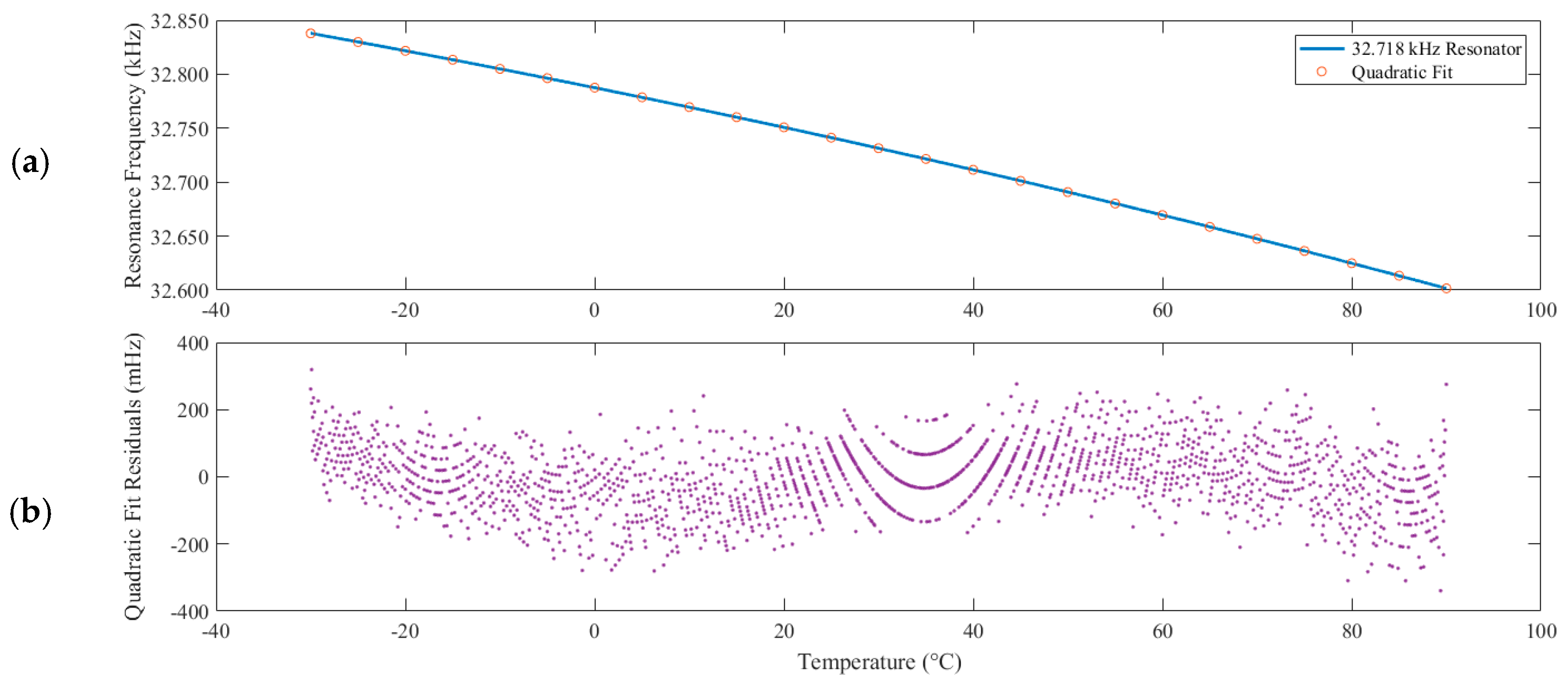
As sensor a temperature sensing oscillator (TSXO) is used, implemented as tuning fork resonator. With its high-Q factor and low frequency in the kHz range it achieves long ringing times. For the measurement in Figure 4 a temperature ramp from −30 °C to +90 °C is applied to the resonator in a climate chamber. It is interrogated using the burst mode technique and the temperature dependent resonance frequency is measured with a gated FFT in the unforced time frame, shown in Figure 3a as the red area. The excitation frequency is adjusted over the temperature ramp by setting it to the previously obtained resonance frequency completing the feedback chain of the presented digital-gated phased-locked loop [5].
The TSXO shows a quadratic temperature response with a sensitivity of −1.94 Hz/°C at 25 °C. The fitted curve has a value for R-squared of 1.0 and 4.3552 as norm of residuals with 1819 points. The parabola patterns in the residual plot suggest that the main reason for the residuals can be attributed to the quantization error of the temperature sensor used as reference with a resolution of 0.1 °C. The currently used FFT frequency bandwidth resolution of 0.34 Hz is limiting the temperature resolution to 0.17 °C. As the Cramer Rao bound [6] is much lower, a better resolution for the temperature can be achieved.
5. Conclusions
This paper has presented, an instrumentation technique for extracting a resonance frequency of a high-Q resonator across a wireless ultrasonic channel. Passive wireless measurement of temperature is presented along with a proof of concept of the wireless and passive operation of the device. Temperature resolution of 0.17 °C and a measurement range of 350 mm has been demonstrated. It has been found that design and implementation of the presented system requires careful matching the resonance frequency and impedance between the transducer and the resonator. In addition, and depending on the noise levels of the environment, the Q factor of the resonator must be high (~100,000) for precise wireless extraction of the resonance frequency.
The novel wireless sensing technique presented in this contribution has significant potential applications with respect to measurements on moving parts, inside enclosed cavities and in submerged environments.
Acknowledgments
The authors would like to thank RSSI GmbH for their kind support in providing samples of the temperature sensitive resonators and Daniel Vössing for the very useful feedback and comments.
Conflicts of Interest
The authors declare no conflict of interest. The founding sponsors had no role in the design of the study; in the collection, analyses, or interpretation of data; in the writing of the manuscript, and in the decision to publish the results.
References
- Nopper, R.; Has, R.; Reindl, L. A Wireless Sensor Readout System—Circuit Concept, Simulation, and Accuracy. IEEE Trans. Instrum. Meas. 2011, 60, 2976–2983. [Google Scholar] [CrossRef]
- Hagelauer, A.; Ussmueller, T.; Weigel, R. SAW and CMOS RFID transponder-based wireless systems and their applications. In Proceedings of the 2012 IEEE International Frequency Control Symposium (FCS), Baltimore, MD, USA, 21–24 May 2012; pp. 1–6. [Google Scholar]
- Shoudy, D.A.; Saulnier, G.J.; Scarton, H.A.; Das, P.K.; Roa-Prada, S.; Ashdown, J.D.; Gavens, A.J. P3F-5 An Ultrasonic Through-Wall Communication System with Power Harvesting. In Proceedings of the 2007 IEEE Ultrasonics Symposium Proceedings, New York, NY, USA, 28–31 October 2007; pp. 1848–1853. [Google Scholar]
- Reindl, L.; Scholl, G.; Ostertag, T.; Scherr, H.; Wolff, U.; Schmidt, F. Theory and application of passive SAW radio transponders as sensors. IEEE Trans. Ultrason. Ferroelectr. Freq. Control 1998, 45, 1281–1292. [Google Scholar] [CrossRef] [PubMed]
- Pohl, A.; Ostermayer, G.; Seifert, F. Wireless sensing using oscillator circuits locked to remote high-Q SAW resonators. IEEE Trans. Ultrason. Ferroelectr. Freq. Control 1998, 45, 1161–1168. [Google Scholar] [CrossRef] [PubMed]
- Kalinin, V. Comparison of frequency estimators for interrogation of wireless resonant SAW sensors. In Proceedings of the 2015 Joint Conference of the IEEE International Frequency Control Symposium & the European Frequency and Time Forum, Denver, CO, USA, 12–16 April 2015; pp. 498–503. [Google Scholar]
Figure 1.
Basic concept of a wireless readout of a resonance frequency using ultrasonic wave propagation.
Figure 1.
Basic concept of a wireless readout of a resonance frequency using ultrasonic wave propagation.

Figure 2.
Measurement setup with laboratory equipment for the proof of concept with a quartz tuning fork resonator.
Figure 2.
Measurement setup with laboratory equipment for the proof of concept with a quartz tuning fork resonator.

Figure 3.
Backscattered signal: (a) Excitation pulse width of 0.502 s and ringing of the high-Q factor resonator at resonance frequency with an envelope fit (red dashed) to the decay for Q factor calculation; (b) Shift from excitation frequency to resonance frequency.
Figure 3.
Backscattered signal: (a) Excitation pulse width of 0.502 s and ringing of the high-Q factor resonator at resonance frequency with an envelope fit (red dashed) to the decay for Q factor calculation; (b) Shift from excitation frequency to resonance frequency.

Figure 4.
(a) Characterization of the resonance frequency of the sensor element as function of the temperature with a quadratic fit (b) Residuals of the fitted curve in mHz.
Figure 4.
(a) Characterization of the resonance frequency of the sensor element as function of the temperature with a quadratic fit (b) Residuals of the fitted curve in mHz.

Publisher’s Note: MDPI stays neutral with regard to jurisdictional claims in published maps and institutional affiliations. |
© 2017 by the authors. Licensee MDPI, Basel, Switzerland. This article is an open access article distributed under the terms and conditions of the Creative Commons Attribution (CC BY) license (https://creativecommons.org/licenses/by/4.0/).
Share and Cite
MDPI and ACS Style
Aftab, T.; Schaechtle, T.; Hoppe, J.; Shi, D.; Schott, D.; Reindl, L. Ultrasonic Coupled Passive Wireless Oscillating Sensor System. Proceedings 2017, 1, 574. https://doi.org/10.3390/proceedings1040574
AMA Style
Aftab T, Schaechtle T, Hoppe J, Shi D, Schott D, Reindl L. Ultrasonic Coupled Passive Wireless Oscillating Sensor System. Proceedings. 2017; 1(4):574. https://doi.org/10.3390/proceedings1040574
Chicago/Turabian StyleAftab, Taimur, Thomas Schaechtle, Joachim Hoppe, Di Shi, Dominik Schott, and Leonhard Reindl. 2017. "Ultrasonic Coupled Passive Wireless Oscillating Sensor System" Proceedings 1, no. 4: 574. https://doi.org/10.3390/proceedings1040574