
Real-Time Imaging Processing of Squint Spaceborne SAR with High-Resolution Based on Nonuniform PRI Design


School of Automation, Central South University, Changsha 410083, China
*
Author to whom correspondence should be addressed.
Remote Sens. 2022, 14(15), 3725; https://doi.org/10.3390/rs14153725
Submission received: 20 June 2022
/
Revised: 29 July 2022
/
Accepted: 30 July 2022
/
Published: 3 August 2022
(This article belongs to the Topic High-Resolution Earth Observation Systems, Technologies, and Applications)
Abstract
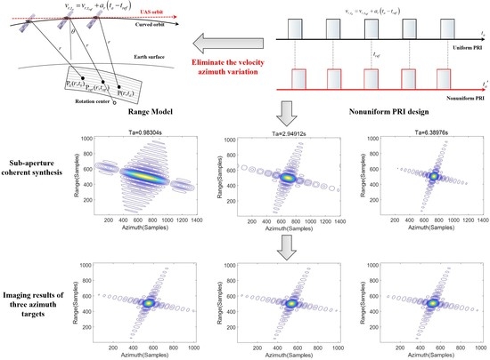
:The real-time imaging research of squint spaceborne synthetic aperture radar (SAR) with high resolution has significant value in both military and civil fields, which makes it a hot issue in SAR research. It is necessary to solve the contradictory problems of nonlinear trajectory and efficient imaging at the same time in order to achieve the two goals, high-resolution and real-time imaging. A large number of complex operations are required in the accurate correction algorithms for nonlinear trajectory, which will reduce the imaging efficiency, and this problem becomes more prominent with the improvement of resolution. To solve the above problems, this paper proposes a new real-time imaging processing of squint high-resolution SAR, which eliminates the velocity–azimuth variation caused by nonlinear trajectory in the data acquisition stage through nonuniform pulse repetition interval (PRI) design. The imaging efficiency has been greatly improved because the new method avoids the complex azimuth resampling operation. Simulation experiments verify the effectiveness of the method.
1. Introduction
As a special detection and imaging technology, synthetic aperture radar (SAR) is an active imaging method because it actively transmits and receives electromagnetic signals [1]. Compared with conventional optical imaging technology, SAR has the advantages of all-day and all-time imaging despite the influence of light and weather. Therefore, SAR has played an irreplaceable role in many industries [2,3]. The current mainstream SAR systems can be divided into two categories [4,5]. (1) In airborne SAR, the radar is carried on aircraft and its detection altitude is basically in the atmosphere. Although the cost is low, the limitation of airborne SAR is still obvious due to the national boundary and incapability of free navigation around the world. (2) In spaceborne SAR, the radar is carried on satellite, and its detection altitude is above the atmosphere. Compared with airborne SAR, the most significant advantage is that spaceborne SAR can image any region of the world as needed, for there exists no restriction of satellite movement in airspace around the globe [6]. Therefore, spaceborne SAR has important application value in scientific research and commerce, especially in the military field. With the continuous development of spaceborne SAR technology, the pursuit of higher resolution and real-time imaging has gradually become two main research directions [7,8].
During the SAR operation, the timeliness of imaging is usually not necessary. However, in some special application scenarios such as military investigation or disaster assessment, the imaging efficiency is required to be as fast as possible [9]. There are two main strategies for realizing the research goal of improving imaging efficiency. One is using more efficient imaging algorithms to reduce complex computing processing [10]. The other is overlapping subaperture algorithm (OSA) [11]. The work flow of conventional full-aperture imaging is the data acquisition at the first step and then complex data processing, which is a serial work mode with low efficiency. The core workflow of OSA is processing and imaging the previous subaperture data while acquiring the next subaperture data. Then, the coherent synthesis is applied on each subaperture image to obtain a complete full-aperture image gradually. Because data acquisition and data processing are carried out simultaneously in OSA, it has high imaging efficiency. Generally, the full-aperture image can be quickly completed after the acquisition of the last subaperture data [12]. It should be noted that the traditional OSA can not be directly applied to the high-resolution spaceborne SAR imaging process, although it is believed to be an effective real-time imaging strategy. Some modifications must be made in the OSA processing because the orbit nonlinearity needs to be solved when using high-resolution spaceborne SAR imaging [13].
Influenced by the earth’s curvature, the orbit of spaceborne SAR has obvious nonlinear characteristics while flying. Specifically, the orbit is curved not straight, and the velocity–azimuth variation is not constant [14,15,16]. With the continuous improvement of imaging resolution and squint angle, the damage to image quality caused by nonlinear trajectory becomes more and more severe [17]. In order to solve the nonlinear problem of squint spaceborne SAR trajectory, a variety of range models have been developed according to different resolution requirements, such as the squint hyperbola model (SHRM) [18], the modified equivalent squint range model (MESRM) [19,20] and the motion compensation range model (MCRM) [21]. However, when the resolution reaches the decimeter level, the target at the azimuth edge will be seriously defocused with the increase of azimuth mapping width, especially in the sliding spotlight mode. Based on the squint equivalent acceleration range model (SEARM), the velocity scaling algorithm (VSA) is proposed to solve the problem of velocity–azimuth variation based on that range model [22]. Although the image quality of VSA is good, the algorithm is not suitable for real-time imaging. The main reason is that VSA needs azimuth resampling, which results in a large number of interpolation operations that greatly reduce the imaging efficiency.
To sum up, in order to realize real-time imaging of high-resolution spaceborne SAR, the problem of trajectory nonlinearity must be solved while ensuring imaging efficiency. This paper proposes a real-time imaging processing for squint high-resolution spaceborne SAR based on a nonuniform pulse repetition interval (PRI) design. The nonuniform PRI design has solved the problem of velocity–azimuth variation when the radar transmits and receives signals in the data acquisition stage, which effectively avoids the complex azimuth resampling in [22] and meets the requirements of real-time imaging. It should be noted that reference [13] proposed a real-time imaging processing based on variable pulse repetition frequency (PRF). However, that research is for the side-looking mode with no squint angle, the range model, orbit error, and range cell migration correction (RCMC) method are no longer applicable to squint spaceborne imaging in this paper. This is also one of the problems that need to be solved in this paper.
The main contents of this paper are as follows: In Section 2, aiming at the nonlinear trajectory of spaceborne SAR, the squint range model is gradually established, and some problems are summarized. In Section 3, based on the above squint range model, the real-time imaging processing based on nonuniform PRI design is introduced in detail. In Section 4, the effect of subaperture image coherent synthesis and the whole scene imaging quality are verified by simulation. The influence of ignoring the high-order term range variation is quantitatively explained. In Section 5, the efficiency of the proposed method and the algorithm in [22] is discussed. The conclusion is drawn in Section 6.
2. Range Model and Problem Formulation
Firstly, the range model that meets the imaging requirements of squint high-resolution spaceborne SAR is gradually established in this section. Secondly, the problems and solutions in the case of squint high-resolution real-time imaging are briefly analyzed, which is helpful for the new method proposed in the next section.
2.1. Range Model
With the improvement of synthetic aperture time and resolution, the traditional SHRM can no longer meet the imaging requirements. Under this circumstance, the nonlinear problem of trajectory must be considered. When the azimuth mapping width is narrow, especially for spotlight mode imaging, the MCRM [21] can be established by setting the center target of the scene as the reference:
where is the azimuth time, is the Doppler center time, r is the Doppler center oblique distance, is the squint angle at the Doppler center time, is the equivalent velocity of the satellite, and is the motion error with the center point as the reference. It should be noted that the MCRM model is established with reference to the center point, making the target at the scene center well focused. However, the targets far away from the center will become azimuth defocusing, which will become more severe when the distance is larger. Obviously, this model is unsuitable for wide swath imaging and cannot meet the requirements of high-resolution imaging in sliding spotlight mode.
According to the analysis of [22], the speed of spaceborne SAR changes slowly along the azimuth direction, which can be regarded as uniformly accelerated straight (UAS) motion, as shown in Figure 1. Then, the velocity of the satellite at time can be expressed as , where is the reference azimuth time, generally set as 0, and represents the equivalent velocity of the reference target. Generally, the scene center is selected as the reference target position. is the acceleration. By integrating the velocity from to , the moving position of the satellite can be obtained. Then, the slant range model is obtained as follows:
The above range model has considered the velocity–azimuth variation but neglected the influence of the curved orbit. By combining with the fourth-order range model proposed in [23] and the Taylor expansion of Equation (2), the SEARM [22] can be obtained:
The last three high-order terms are the error between the and . The coefficients of high-order terms are expressed as:
where , , , and are the first-order, second-order, third-order, and fourth-order coefficients of , respectively. It can be seen that the coefficients changes with the range r and azimuth time , but the range variation is small. It can be considered as non-spatially variable in the whole imaging scene, and the range r can be replaced by the reference range . The impact of this approximation will be explained in Section 4.3. Equation (4) can be expressed as:
Based on , the radar echo can be expressed as:
where and represent the range and azimuth window functions, respectively, is the fast time in the range direction, c is the speed of light, is the wavelength, and is the range frequency modulation.
2.2. Problem Formulation
The research goal of this paper is to realize the real-time imaging of squint high-resolution spaceborne SAR. Based on the above range model, a simple summary of the problems that need to be solved is drawn, which is convenient for the next section to introduce the real-time imaging processing of nonuniform PRI design.
(1) Real-time: In order to improve the imaging efficiency, the OSA imaging method is adopted. Considering that the subaperture imaging and data acquiring can be carried out at the same time, the OSA avoids the waste of time caused by waiting for data acquisition during full aperture imaging.
(2) Curved trajectory: Compared with the conventional range model, there is a high-order term in Equation (6) introduced by the curved trajectory. Fortunately, this high-order term is considered to be non-spatially variable, so it can be uniformly compensated based on the scene center parameters before other processing.
(3) Velocity–azimuth variation: Even if the influence of curved trajectory is eliminated, the expression under the root of Equation (3) is still different from the conventional squint range model due to the velocity–azimuth variation. So, the conventional imaging method cannot be directly used for data processing. Under the real-time requirements, it is necessary to find a method to eliminate the impact of velocity–azimuth variation without adding additional data processing. It is worth mentioning that the VSA proposed by [22] requires additional complex interpolation operations during azimuth resampling processing. The additional processing will reduce the imaging efficiency and dose not meet the requirements of real-time imaging.
(4) Squint imaging: The range model, orbit error, and RCMC method no longer apply to this paper because the research [13] focused on the side-looking mode without squint angle. Therefore, the accurate range model and orbit error based on the squint SAR situation must be established first. As for RCMC methods, there are various approximations in range Doppler algorithm (RDA) [24] and chirp-scaling algorithm (CSA) [25,26], and the approximation error will be enlarged with the increase of squint angle. Therefore, the above two kinds of algorithms are generally not used for the squint high-resolution SAR. Instead, the range migration correction algorithm (RMA) [27,28] is used in this paper for subaperture imaging processing.
3. Real-Time Imaging Processing Based on Nonuniform PRI Design
In this section, the real-time imaging processing for nonuniform PRI design will be proposed based on the SEARM. Figure 2 is the new imaging method flow chart. Firstly, the nonuniform PRI design eliminates the velocity–azimuth variation directly in hardware when the radar transmits and receives signals. Secondly, the data are processed by subaperture imaging, which is different from the conventional RMA processing. It is necessary to compensate for the high-order term caused by curved trajectory before processing. Finally, the subaperture images are synthesized coherently in time order to obtain a complete high-resolution SAR image.
3.1. Nonuniform PRI Design
In fact, the whole system of spaceborne SAR is composed of two subsystems: satellite and radar. Generally, the motion parameters of the satellite cannot be changed casually during the in-orbit flight. Whether the problem of velocity–azimuth variation can be solved by changing the radar parameters is the core idea of the new real-time imaging method proposed in this paper.
The range model in Equation (3) is derived based on the conventional uniform PRI design. In order to eliminate the influence of velocity–azimuth variation, the PRI of radar can be set as nonuniform, and the new PRI is:
Submitting Equation (3) to (7), the range model can be expressed as:
where is the expression of the last high-order terms in Equation (3) after nonuniform PRI design. It can be seen that after the nonuniform PRI design of Equation (7) is adopted, the new range model is composed of two parts. The first part has eliminated the influence of velocity–azimuth variation, which is the same as the conventional squint range model. After eliminating the high-order term, the conventional imaging method can be used for imaging. In order to facilitate the derivation of the imaging processing, the variable in and is still represented by in the following sections. It should be noted that the nonuniform PRI design here does not add additional data processing.
3.2. Subaperture Imaging
This step mainly carries out high-order term compensation and standard RMA processing for each subaperture data. First, the range model of the kth subaperture obtained can be expressed as:
where is the azimuth time of subaperture data, and is the center time of the kth subaperture. In combination with Equation (6), the radar echo of the kth subaperture can be expressed as:
Equation (10) is transformed to a two-dimensional frequency domain by the stationary phase method [27]:
The last term in Equation (11) is the high-order error caused by the curved trajectory, which can be expressed as:
Although the higher-order term is spatially variable with the range, it changes to small in the imaging scene, so it can be considered as non-spatially variable. The center distance is used as a reference to calculate the error and compensate for it uniformly. The compensation function is:
After the high-order error term is compensated, the echo signal form is the same as that under the ordinary squint hyperbolic model. The standard RMA can be used to process the subaperture data [27], and the subaperture image is obtained finally:
where is the signal bandwidth and is the azimuth bandwidth. So far, the subaperture radar image has been obtained. In the next step, the subaperture image coherent synthesis processing will be carried out.
3.3. Coherent Synthesis of Subaperture Image
It can be seen from Equation (14) that it is necessary to place each subaperture image on the corresponding azimuth time to realize coherent synthesis. To ensure the azimuth position accuracy, the offset compensation function is generally multiplied in the azimuth frequency domain:
After all the subaperture images are moved to the correct position, a coherent synthesis image of full-aperture can be obtained.
4. Verification by Simulated Results
This section will verify the imaging quality of the real-time method proposed in this paper and quantitatively show the influence of ignoring the range variation of high-order term. As shown in Figure 3, a set of targets is placed in the observation area, and target 5 is at the scene center.
The orbit data of the satellite and the main radar parameters required for the simulation experiment are shown in Table 1 and Table 2.
4.1. Verification of Subaperture Coherent Synthesis
The effectiveness of the subaperture imaging coherent synthesis is verified in this subsection. The experiment is only conducted for the central target 5 without considering other targets. After using the method proposed in this paper, the results under different synthetic aperture time are shown in Figure 4. It should be noted that all the imaging results shown in this paper are −32 db contour maps, and there is no windowing in the imaging process.
Figure 4a is the imaging result of the first subaperture, in which the side lobe and main lobe are clearly separated, indicating that the imaging of this subaperture has reached an ideal state. However, due to the short synthetic aperture time, the azimuth resolution is low. By observing Figure 4a,b, it can be seen that with the increase of coherent synthetic subaperture, the azimuth resolution of the target is gradually improved, which shows that the method proposed in this paper is effective. The high-resolution SAR images can be obtained through coherent synthesis.
4.2. Verification of Full Scene Image
In order to verify the imaging quality of the new real-time processing, especially for targets far away from the scene center, the conventional OSA based on the hyperbolic model, OSA based on MCRM, and the method proposed in this paper are used for the nine targets in Figure 3. After all subaperture imaging and coherent synthesis are completed, the final imaging results are shown in Figure 5, Figure 6 and Figure 7.
It can be seen from Figure 5 that all the targets are defocused by using OSA under the squint HRM. In Figure 6, the targets at the azimuth center, target 2, target 5, and target 8, are well focused using OSA under the MCRM. However, the targets far away from the azimuth center are defocused seriously. This is consistent with the previous analysis: that is, the farther away from the azimuth center, the greater the error and the worse the imaging quality.
Figure 7 shows the imaging results of the method proposed in this paper. Compared with the imaging results of the other two methods, the imaging quality has been significantly improved, and the targets at the azimuth edge have also been well focused, which proves the effectiveness of the method proposed in this paper. The nonuniform PRI design can solve the problem of velocity–azimuth variation.
4.3. Quantification of Approximation Influence for High-Order Terms
In Equation (7), the higher-order term coefficient is range variation, but the compensation function in Equation (13) compensates the scene uniformly. In order to quantify the influence of this approximation, three targets are set at 1.0 km, 2.5 km and 3.5 km away from the reference range . Based on the parameters in Table 1 and Table 2, the errors of the high-order terms after using the approximation are shown in Figure 8. It can be seen that the error caused by approximation will be enlarged with the increase of distance and synthetic aperture time . However, the maximum error phase calculated at a distance of 3.5 km away from the reference range is 0.4 rad, which is still less than . Therefore, it can be concluded that it is feasible to ignore the range variation of higher-order terms and use the scene center parameters for unified compensation.
5. Discussion
In Section 4.2, the other two methods in the comparison experiment obviously fail to meet the requirements of high-resolution imaging. The VSA has been proven in [22] to obtain well-focused imaging results. However, this paper does not make a comparison in Section 4.2; the main reason is that the algorithm proposed in [22] does not meet the requirements of real-time imaging. Firstly, the algorithm is a full-aperture imaging method, which is not as efficient as OSA. Secondly, although the full-aperture algorithm can be modified to OSA, the azimuth resampling processing will still increase a lot of interpolation operations and reduce the imaging efficiency. Compared with all of the above methods, the method proposed in this paper uses a nonuniform PRI design to solve the velocity–azimuth variation at the stage of the radar transmitting and receiving signal. It no longer requires complex interpolation operation and takes the imaging efficiency into account while ensuring the imaging quality.
Next, we quantitatively analyze the computational complexity of the proposed method compared with VSA [22]. The VSA includes two range FFT/FFTs, four azimuth FFT/FFTs, eight phase multiplications (– in [22]), and two interpolations. Suppose the number of sampling points for the range and azimuth is M and N, respectively, and the length of the interpolation kernel is L. So, the computational complexity of the VSA method is:
The new method proposed in this paper inculdes two range FFT/FFTs, two azimuth FFT/FFTs, and three phase multiplications. The computational complexity of the proposed method is:
For simplicity, the range and azimuth sampling points are set to be the same, that is . The length of the interpolation kernel is set as 16, that is . The computational complexity of the proposed method compared with the VSA [22] is shown in Figure 9. It can be seen that with the increase of the synthetic aperture time , the computational complexity of the new method gradually decreases, which means the real-time effect becomes evident.
6. Conclusions
A real-time imaging processing for Squint spaceborne SAR based on nonuniform PRI design is proposed in this paper. Firstly, in order to meet the requirements of high-resolution imaging, the SEARM is established to meet the imaging accuracy. Through the nonuniform PRI design, the problem of velocity–azimuth variation under spaceborne nonlinear trajectory is solved in the radar data acquisition stage. By modifying the traditional OSA processing, the problem of curved trajectory is eliminated before subaperture imaging processing. Finally, the imaging quality of the real-time processing is verified by simulation. Because the new method solves the problem of velocity–azimuth variation through hardware design rather than data processing, it avoids complex interpolation, so the imaging efficiency is greatly improved. To sum up, the method proposed in this paper takes into account both high-resolution and imaging efficiency. It is an effective real-time imaging processing for squint high-resolution spaceborne SAR.
Author Contributions
Conceptualization, B.L. and Y.J.; methodology, Y.J. and J.C.; investigation, Y.J.; verification, Y.J.; writing—original draft preparation, Y.J. and Y.X.; writing—review and editing, B.L. and M.X.; funding acquisition, B.L. All authors have read and agreed to the published version of the manuscript.
Funding
This research was funded by National Natural Science Foundation of China (General Program) under grant 62171475.
Conflicts of Interest
The authors declare no conflict of interest. The funders had no role in the design of the study, in the collection, analyses, or interpretation of data, in the writing of the manuscript, or in the decision to publish the results.
References
- Kazuo, O. Recent Trend and Advance of Synthetic Aperture Radar with Selected Topics. Remote Sens. 2013, 5, 716–807. [Google Scholar]
- Tao, M.; Su, J.; Huang, Y.; Wang, L. Mitigation of Radio Frequency Interference in Synthetic Aperture Radar Data: Current Status and Future Trends. Remote Sens. 2019, 11, 2438. [Google Scholar] [CrossRef] [Green Version]
- Ferretti, A.; Fumagalli, A.; Novali, F.; Prati, C.; Rucci, A. A New Algorithm for Processing Interferometric Data-Stacks: SqueeSAR. IEEE Trans. Geosci. Remote Sens. 2011, 49, 3460–3470. [Google Scholar] [CrossRef]
- Chen, J.; Xing, M.; Yu, H.; Liang, B.; Peng, J.; Sun, G.-C. Motion Compensation/Autofocus in Airborne Synthetic Aperture Radar: A Review. IEEE Geosci. Remote Sens. Mag. 2022, 10, 185–206. [Google Scholar] [CrossRef]
- Jin, Y.; Chen, J.; Xia, X.G.; Liang, B.; Xing, M. Ultrahigh-Resolution Autofocusing for Squint Airborne SAR Based on Cascaded MD-PGA. IEEE Geosci. Remote Sens. Lett. 2021, 99, 1–5. [Google Scholar] [CrossRef]
- Krieger, G.; Moreira, A.; Fiedler, H.; Hajnsek, I.; Werner, M.; Younis, M.; Zink, M. TanDEM-X: A Satellite Formation for High-Resolution SAR Interferometry. IEEE Trans. Geosci. Remote Sens. 2007, 45, 3317–3341. [Google Scholar] [CrossRef] [Green Version]
- Wang, Z.; Li, Z.; Liu, Y.; Peng, J.; Mills, J. A New Processing Chain for Real-Time Ground-Based SAR (RT-GBSAR) Deformation Monitoring. Remote Sens. 2019, 11, 2437. [Google Scholar] [CrossRef] [Green Version]
- Sun, G.C.; Liu, Y.; Xiang, J.; Liu, W.; Chen, J. Spaceborne Synthetic Aperture Radar Imaging Algorithms: An Overview. IEEE Geosci. Remote Sens. Mag. 2021, 10, 161–184. [Google Scholar] [CrossRef]
- Raman, B.S.; Moreira, A.; Spielbauer, R.; Franceschetti, G. Real-Time Synthetic Aperture Radar (SAR) Processing for Large Squint Angles; International Society for Optics and Photonics: Rome, Italy, 1994; pp. 2–8. [Google Scholar]
- Jia, G.; Buchroithner, M.; Chang, W.; Li, X. Simplified Real-Time Imaging Flow for High-Resolution FMCW SAR. Remote Sens. 2013, 12, 973–977. [Google Scholar]
- Moreira, A. Real-time synthetic aperture radar (SAR) processing with a new subaperture approach. IEEE Trans. Geosci. Remote Sens. 1992, 30, 714–722. [Google Scholar] [CrossRef]
- Sun, G.C.; Liu, Y.; Xing, M.; Wang, S.; Guo, L.; Yang, J. A Real-Time Imaging Algorithm Based on Sub-Aperture CS-Dechirp for GF3-SAR Data. Sensors 2018, 18, 2562. [Google Scholar] [CrossRef] [PubMed] [Green Version]
- Chen, J.; Zhang, J.; Jin, Y.; Yu, H.; Yang, D.G. Real-Time Processing of Spaceborne SAR Data with Nonlinear Trajectory Based on Variable PRF. IEEE Trans. Geosci. Remote Sens. 2022, 60, 1–12. [Google Scholar] [CrossRef]
- Chen, J.; Zhang, J.; Liang, B.; Yang, D. A General Method of Series Reversion for Synthetic Aperture Radar Imaging. IEEE Geosci. Remote Sens. Lett. 2022, 19, 1–5. [Google Scholar] [CrossRef]
- Hu, C. An Improved CS Algorithm Based on the Curved Trajectory in Geosynchronous SAR. IEEE J. Sel. Top. Appl. Earth Observ. Remote Sens. 2012, 5, 795–808. [Google Scholar] [CrossRef]
- Wu, Y.; Sun, G.C.; Yang, C.; Yang, J.; Xing, M.; Bao, Z. Processing of Very High Resolution Spaceborne Sliding Spotlight SAR Data Using Velocity Scaling. IEEE Trans. Geosci. Remote Sens. 2016, 54, 1505–1518. [Google Scholar] [CrossRef]
- Wei, X.; Deng, Y.; Huang, P.; Wang, R. Full-Aperture SAR Data Focusing in the Spaceborne Squinted Sliding-Spotlight Mode. IEEE Trans. Geosci. Remote Sens. 2014, 52, 4596–4607. [Google Scholar] [CrossRef]
- Lanari, R.; Zoffoli, S.; Sansosti, E.; Fornaro, G.; Serafino, F. New approach for hybrid strip-map/spotlight SAR data focusing. Radar Sonar Navig. IEE Proc. 2001, 148, 363–372. [Google Scholar] [CrossRef]
- He, F.; Chen, Q.; Dong, Z.; Sun, Z. Processing of Ultrahigh-Resolution Spaceborne Sliding Spotlight SAR Data on Curved Orbit. IEEE Trans. Aeros. Electron. Syst. 2013, 49, 819–839. [Google Scholar] [CrossRef]
- Wang, P.; Liu, W.; Chen, J.; Niu, M.; Yang, W. A High-Order Imaging Algorithm for High-Resolution Spaceborne SAR Based on a Modified Equivalent Squint Range Model. IEEE Trans. Geosci. Remote Sens. 2014, 53, 1225–1235. [Google Scholar] [CrossRef] [Green Version]
- Prats-Iraola, P. On the Processing of Very High Resolution Spaceborne SAR Data. IEEE Trans. Geosci. Remote Sens. 2014, 52, 6003–6016. [Google Scholar] [CrossRef] [Green Version]
- Sun, G.C.; Wu, Y.; Yang, J.; Xing, M.; Bao, Z. Full-Aperture Focusing of Very High Resolution Spaceborne-Squinted Sliding Spotlight SAR Data. IEEE Trans. Geosci. Remote Sens. 2017, 55, 3309–3321. [Google Scholar] [CrossRef]
- Eldhuset, K. A new fourth-order processing algorithm for spaceborne SAR. IEEE Trans. Aerosp. Electron. Syst. 1998, 34, 824–835. [Google Scholar] [CrossRef] [Green Version]
- Luo, Y.; Zhao, B.; Han, X.; Wang, R.; Song, H.; Deng, Y. A Novel High-Order Range Model and Imaging Approach for High-Resolution LEO SAR. IEEE Trans. Geosci. Remote Sens. 2014, 52, 3473–3485. [Google Scholar] [CrossRef]
- Yi, T.; He, Z.; He, F.; Dong, Z.; Manqing, W. Generalized Nonlinear Chirp Scaling Algorithm for High-Resolution Highly Squint SAR Imaging. Sensors 2017, 17, 2568. [Google Scholar] [CrossRef] [PubMed] [Green Version]
- Li, C.; He, M. A Generalized Chirp-Scaling Algorithm for Geosynchronous Orbit SAR Staring Observations. Sensors 2017, 17, 1058. [Google Scholar] [CrossRef] [PubMed] [Green Version]
- Xu, G.; Xing, M.; Zhang, L.; Bao, Z. Robust Autofocusing Approach for Highly Squinted SAR Imagery Using the Extended Wavenumber Algorithm. Sensors 2013, 51, 5031–5046. [Google Scholar]
- Yang, J.; Sun, G.; Xing, M.; Xia, X.; Liang, Y.; Bao, Z. Squinted TOPS SAR Imaging Based on Modified Range Migration Algorithm and Spectral Analysis. IEEE Geosci. Remote Sens. Lett. 2017, 11, 1707–1711. [Google Scholar] [CrossRef]
Figure 1.
Observation geometry of squint spaceborne SAR with curved trajectory.

Figure 2.
Flowchart of the proposed real-time imaging processing.

Figure 3.
Target distribution for simulations.

Figure 4.
Coherent synthesis results of the proposed real-time processing with a synthetic aperture time of about (a) 0.98 s, (b) 1.97 s, (c) 2.95 s, (d) 3.93 s, (e) 4.92 s, and (f) 6.39 s.
Figure 4.
Coherent synthesis results of the proposed real-time processing with a synthetic aperture time of about (a) 0.98 s, (b) 1.97 s, (c) 2.95 s, (d) 3.93 s, (e) 4.92 s, and (f) 6.39 s.

Figure 5.
Real-time imaging results of typical OSA with the traditional squint hyperbolic model. (a–c) Results of targets 1–3. (d–f) Results of targets 4–6. (g–i) Results of targets 7–9.
Figure 5.
Real-time imaging results of typical OSA with the traditional squint hyperbolic model. (a–c) Results of targets 1–3. (d–f) Results of targets 4–6. (g–i) Results of targets 7–9.

Figure 6.
Real-time imaging results of modified OSA with MCRM. (a–c) Results of targets 1–3. (d–f) Results of targets 4–6. (g–i) Results of targets 7–9.
Figure 6.
Real-time imaging results of modified OSA with MCRM. (a–c) Results of targets 1–3. (d–f) Results of targets 4–6. (g–i) Results of targets 7–9.

Figure 7.
Real-time imaging results of the proposed method. (a–c) Results of targets 1–3. (d–f) Results of targets 4–6. (g–i) Results of targets 7–9.
Figure 7.
Real-time imaging results of the proposed method. (a–c) Results of targets 1–3. (d–f) Results of targets 4–6. (g–i) Results of targets 7–9.

Figure 8.
Phase error caused by ignoring the range variation of high-order terms.

Figure 9.
Results of computational complexity analysis.


Table 1.
Satelite orbit parameters.
| Parameters | Value |
|---|---|
| Orbit height | 514 km |
| Semi-major axis | 6885 km |
| Orbit eccentricity | 0.0011 |
| Argument of perigee | 97.44 |
| Ascending node | 260 |
| Orbit inclination | 97.44 |
Table 2.
Radar parameters.
| Parameters | Value |
|---|---|
| Carrrier frequency | 9.65 GHz |
| Chirp bandwidth | 500 MHz |
| Working mode | Sliding spotlight |
| Squint angle | 15 |
| Observation time | 10.6496 s |
Publisher’s Note: MDPI stays neutral with regard to jurisdictional claims in published maps and institutional affiliations. |
© 2022 by the authors. Licensee MDPI, Basel, Switzerland. This article is an open access article distributed under the terms and conditions of the Creative Commons Attribution (CC BY) license (https://creativecommons.org/licenses/by/4.0/).
Share and Cite
MDPI and ACS Style
Jin, Y.; Liang, B.; Chen, J.; Xiong, Y.; Xiong, M. Real-Time Imaging Processing of Squint Spaceborne SAR with High-Resolution Based on Nonuniform PRI Design. Remote Sens. 2022, 14, 3725. https://doi.org/10.3390/rs14153725
AMA Style
Jin Y, Liang B, Chen J, Xiong Y, Xiong M. Real-Time Imaging Processing of Squint Spaceborne SAR with High-Resolution Based on Nonuniform PRI Design. Remote Sensing. 2022; 14(15):3725. https://doi.org/10.3390/rs14153725
Chicago/Turabian StyleJin, Yanghao, Buge Liang, Jianlai Chen, Yi Xiong, and Mingyao Xiong. 2022. "Real-Time Imaging Processing of Squint Spaceborne SAR with High-Resolution Based on Nonuniform PRI Design" Remote Sensing 14, no. 15: 3725. https://doi.org/10.3390/rs14153725
Note that from the first issue of 2016, this journal uses article numbers instead of page numbers. See further details here.