1. Introduction
Earth’s gravity field structure and its time variability provide a direct measurement of key aspects of mass distribution and mass transport within the Earth’s system, which comprises oceans, the cryosphere, continental hydrology, solid Earth and atmosphere. The single satellite mission GOCE, with its gradiometer, was operational in 2009–2013, and provided static gravity field products with high spatial resolution in the order of 80–100 km [
1], while the GRACE satellite pair measured monthly snapshots with a resolution of 300–500 km between 2002 and 2017 [
2]. The satellite tandem of GRACE Follow-On (FO) continues to work on the valuable GRACE dataset [
3] that, e.g., helped to quantify the mass ice loss in polar regions due to global warming [
4], confirmed the attribution of the ocean mass influx to the global mean sea level rise [
5] and is essential to quantify processes related to the water cycle [
6].
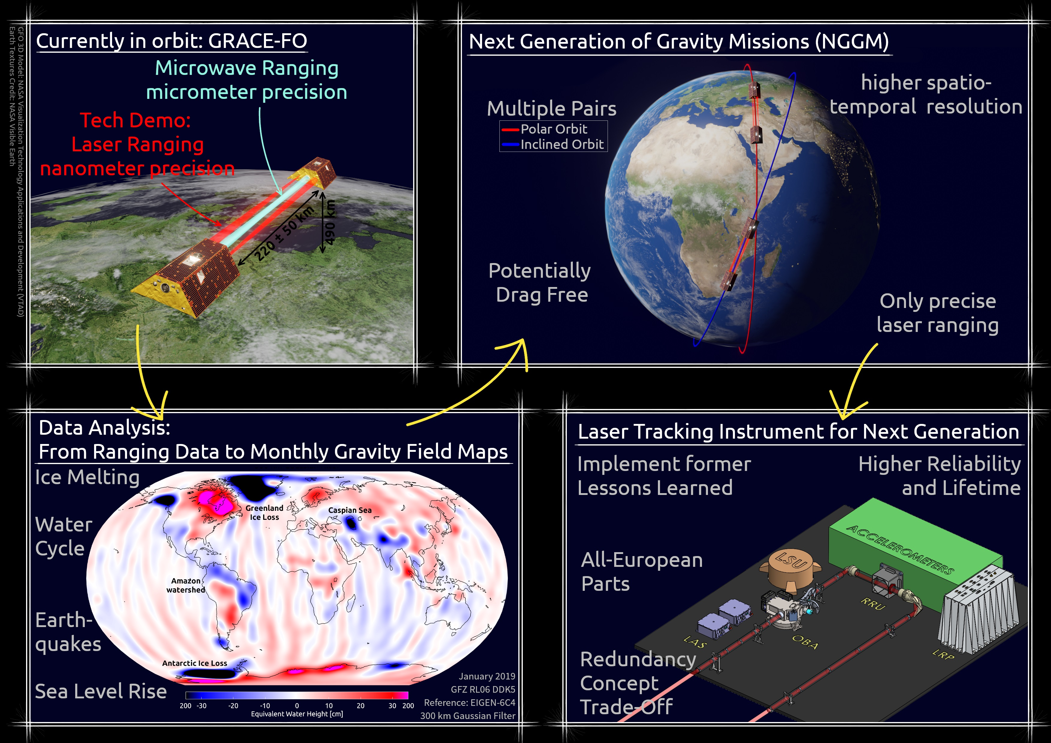
GRACE-FO, led by a US–German collaboration, was designed as a quick successor mission for GRACE, implementing a few lessons learned and hosting an additional novel laser ranging instrument (LRI) as a technology demonstrator in parallel to the conventional microwave ranging instrument (MWI) [
7,
8,
9]. Future missions are currently being studied and developed in the context of a next-generation gravity mission (NGGM) activity under the lead of the European Space Agency (ESA) and in the context of the GRACE-I(carus)/mass change mission (MCM) as a continuation for GRACE-FO lead by a US–German collaboration.
Studies are ongoing on the optimal constellation of these novel satellite pairs with discussions between the ESA, NASA and the German Aerospace Agency DLR in order to maximize the scientific benefit of flying at least two operational satellite pairs with some overlap time, with GRACE-I/MCM potentially being the first pair and the NGGM the second pair. High priority is assigned to a so-called ‘Bender configuration’ [
10], which comprises a polar and an inclined pair. Such a configuration has shown an enhanced spatio-temporal resolution of the resulting gravity field maps in simulations [
11,
12]. In accordance with gravity simulations, the satellite pairs of the upcoming missions are expected to have a satellite separation between 100 and 300 km and to be operated at an altitude between 300 and 500 km.
The distance variations between both satellites in a NGGM or GRACE-like pair are precisely measured by means of a heterodyne laser interferometer, a laser tracking instrument (LTI), with nanometer ranging precision together with many other observations, such as attitude, non-gravitational accelerations, GNSS and others. Currently, the monthly gravity maps of GRACE-FO are mainly limited by accelerometer noise and background model errors, which alias short-term (<30 day) mass variations into the monthly solution. Hence, monthly data products derived from either MWI or LRI have shown only very few differences in GRACE-FO [
13,
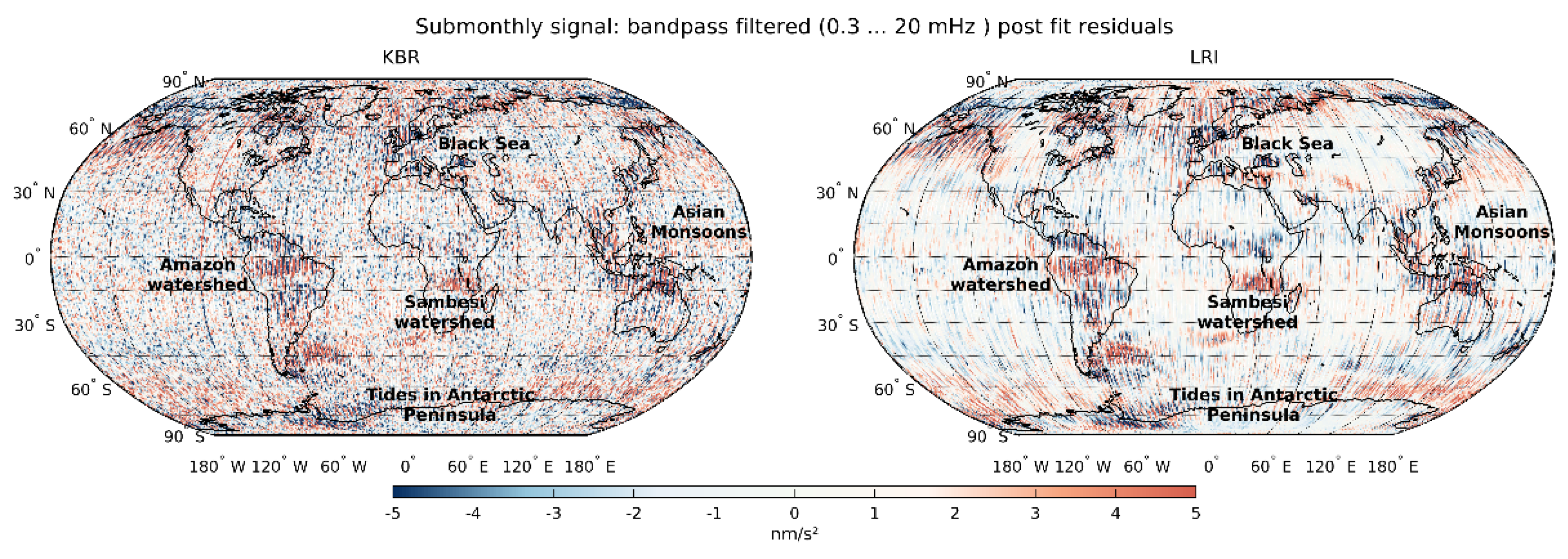
14], since the ranging data quality is not the limiting aspect. However, the low noise of the laser ranging systems allows for the use of post-fit residuals, i.e., the signal that cannot be absorbed by the monthly model, for the detection of short-term mass variations [
15,
16,
17]. Exemplary post-fit residual maps derived with software from GeoForschungsZentrum (GFZ), Potsdam, using the RL06 processing standard [
2], are shown in
Figure 1, obtained as range accelerations by differentiating a time-series of range-rate post-fit values. The figure highlights the low-noise of the laser-based ranging compared to the MWI. This low-noise ranging could be exploited to a larger extent or might even be needed for gravity maps of the NGGM/future missions, considering that multiple pairs could mitigate temporal aliasing effects, background models could steadily continue to advance and the accelerometer noise and satellite platform stability could improve.
Moreover, a benefit from LRI/LTI could be expected when long-term static gravity maps with higher spatial resolution are computed, since the laser instrument allows to better resolve higher frequencies corresponding to high (>90) spherical harmonic degrees [
14,
18].
In this paper, we present the design of a potential LTI system for the NGGM with all-European LTI units, though we remark that the current programmatic baseline foresees a work share between Europe and the US with hardware contributions from both sides to both satellite pairs that are expected to launch in the time frame of 2027 to 2032.
2. LTI Design Principle
We investigated two concepts for the laser tracking instrument over several years under the ESA contract:
The so-called “retroreflector concept”, in which the interferometer is configured very similarly to typical interferometer designs for terrestrial use, with most of the interferometer system mounted on one satellite and only a passive retroreflector placed on the second satellite;
The “transponder concept”, in which the received signal from the first satellite is amplified on the second satellite before being sent back to the first satellite and where both satellites are essentially identical.
A detailed comparison of the two concepts, including requirements, implementation parameters and a noise performance analysis, can be found in [
19]. In addition to the optical power limit necessary to achieve the required noise performance, the onset of cycle slips limited the acceptable carrier to a noise ratio of at least 70 dB-Hz and, thus, the feasibility of the two configurations. While the retroreflector concept allowed for a simpler implementation for distances of up to approximately 30 km and was feasible up to 100 km with increased laser power, only the transponder concept could cover the required inter-satellite distance range from 100 to 300 km, and was, therefore, the selected instrument concept for the NGGM.
The transponder concept LTI consisted of five main units on each satellite, individually placed in the spacecraft:
The instrument control unit with the phasemeter (ICU);
The laser head unit (LHU) as the light source;
The laser stabilization unit (LSU), an optical cavity, to stabilize the laser in frequency;
The optical bench assembly (OBA) to host the interferometer optics;
The off-axis retroreflector unit (RRU) to route the beam to the other spacecraft.
It was completed with a set of optical baffles to reduce straylight and ensure a clear optical aperture, optical fibers between the laser, the laser stabilization unit and the optical bench, as well as the electrical harness. A scale factor measurement system (SFMS) was under discussion to provide an absolute laser frequency reference. A detailed discussion of the individual LTI units is given in
Section 3 below.
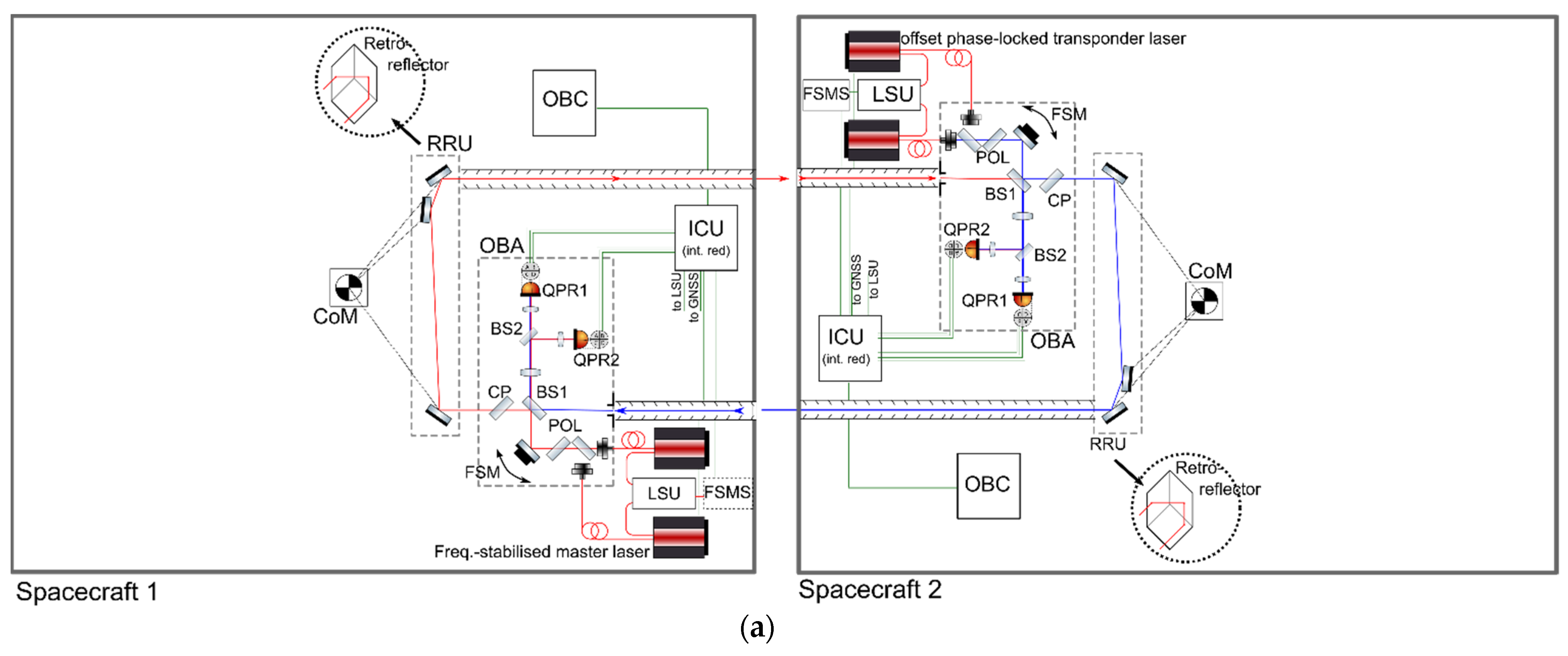
The basic working principle was as follows: The laser head (“master laser”) on satellite one, providing approximately 25 mW of single-mode single-frequency light to the optical bench, was locked to the cavity. The light was then sent to the other satellite via the optical bench and the retroreflector. On the second satellite, the laser frequency of the transponder laser was phase locked to the weak incoming light (≈1 nW) with a fixed frequency offset of some MHz and sent back to the first satellite. At the first satellite, the phase shift between the master and transponder lasers, which contained two times the Doppler shift caused by the relative movement of the satellite, was recorded.
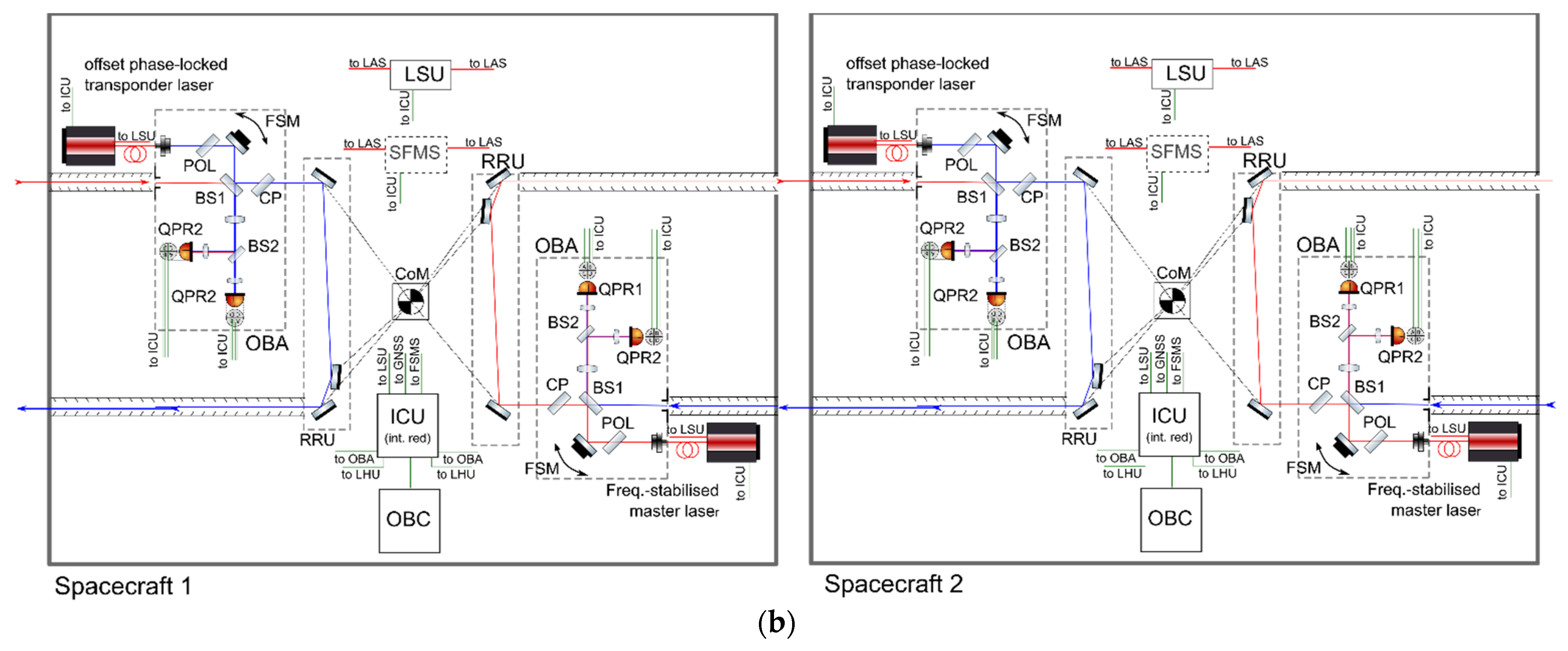
Figure 2 shows the conceptual sketches of the laser tracking instrument in an off-axis transponder configuration with (a) partial redundancy and (b) full redundancy.
In both variants, a cold redundancy for the laser heads was foreseen. The cavity did not need to be redundant on each satellite, because redundancy was achieved by flying one cavity on each spacecraft while needing only one in the constellation. There was the possibility to exchange the master and transponder operational modes. In the partially redundant implementation, each laser had a fiber connected to the single optical bench, providing cold redundancy, not only for the laser itself, but also the fiber and beam collimator. Redundancy switching on the optical bench was achieved via a 50:50 beam splitter, accepting a 3 dB power loss of each signal.
The optical setup on the optical bench(es) routed the beam from the fiber collimators via a steering mirror (FSM) to a beam splitter (BS), which split the beam into one large part that was sent to the other spacecraft (via the retroreflector) and one smaller part that was guided to the photoreceivers to act as a local oscillator. The imaging optics in front of the photoreceivers simultaneously imaged the steering mirror and the entrance aperture onto the photoreceivers, thereby minimizing the effect of beam walk due to beam angle changes, as well as phase errors due to diffraction effects of the baffles and entrance aperture. The compensation plate (CP) minimized the ranging noise introduced by the beam splitter under pointing noise. Only the beam splitter and compensation plate were in the direct measurement path, in which any path length noise (thermally or pointing-driven) directly coupled into the ranging performance.
The pathlength noise of all other optical elements (from fibers to beam splitter, and beam splitter to photoreceivers) was strongly suppressed due to common-mode effects in the local oscillator and roundtrip beams.
The received beam from the other spacecraft with a power between 0.1 and 3 nW (derived from optical link budget calculations for high and low cases in the optical power budget [
19]) entered the optical bench, was reflected at the beam splitter and imaged onto the photoreceivers.
The quadrant photoreceivers on the optical bench were operated in hot redundancy. The heterodyne signal (the beat between the local oscillator and the received beam from the other spacecraft) was read out from the four elements of the photoreceivers, pre-amplified and processed in the phasemeter, which was one part of the instrument control units. The phase variations represented the relative distance change of the two spacecrafts relative to each other, which was the main science signal. The phase differences between the individual segments delivered the pointing information to the other spacecraft with respect to the line of sight, used to drive the attitude control system of the satellite to µrad accuracy using differential wavefront sensing (DWS).
The off-axis retroreflector with its vertex in the center of mass (CoM) of the spacecraft routed the beam around the CoM, thereby enabling the distance measurement from CoM to CoM of the two spacecrafts. It needed to provide a beam co-alignment accuracy (incoming to outgoing beam) of less than 40 µrad and a low-temperature dependency of the vertex position to enable the required ranging performance.
At the second spacecraft (with the laser in transponder mode), the identical instrument configuration was implemented, but differing on the two spacecrafts with respect to the orientation and flight direction (which was the same for both spacecrafts). The received signal from the first spacecraft was used to offset lock the local laser by some MHz, and also to point the second spacecraft to the first spacecraft (by use of the DWS signal). Apart from the mode of operation of the laser, the operation principle was the same as on spacecraft one.
In addition to the higher reliability [
19], the fully redundant LTI allowed for the use of two identical satellites without having to fly one satellite oriented backwards.
2.1. Lessons Learned from GRACE-FO
The LTI transponder design presented here was based on the GRACE-FO LRI heritage, which the authors already contributed in [
9]. Though this instrument was built as a technology demonstrator with reduced requirements on reliability and redundancy, it worked extremely well with almost no unintended interruptions and experienced no degradation after 4 years in orbit. The ranging data were well understood. It was limited at high frequencies (>100 mHz) by the cavity stability to an equivalent ranging noise level of a few 100 picometers per square root of Hertz (pm/√Hz).
Several performance-relevant effects were observed with the LRI, which we considered relevant to improve the NGGM, in addition to the increased redundancy to fulfil the needed reliability as a main instrument. These were mainly the low-frequency tilt-to-length coupling, microshocks of the platform and the absolute laser frequency knowledge:
At mHz frequencies, the tilt-to-length coupling caused a ranging noise level of approx. 500 nm/√Hz. Though the level did not limit the gravity field quality for GRACE-FO since the post-fit residuals were much higher, it needed to be reduced to benefit from the improved foreseen accelerometer performance on the NGGM. The tilt-to-length coupling, given as the product of satellite pointing jitter and coupling factor related to unavoidable residual alignment imperfections, could, in principle, be reduced in post-processing [
20]. The satellite pointing angles in yaw and pitch could be measured with star cameras or—more precisely—by the LTI steering mirror angles, which were controlled based on the interferometric DWS signals, while the corresponding coupling factors were determined with maneuvers that were also used to determine the center-of-mass location. For the NGGM, we planned to implement this correction, which has not been included in the official GRACE-FO LRI processing thus far. In addition, the NGGM satellite platforms are likely to provide a significantly lower pointing noise and perform the fine pointing based on the steering mirror or DWS signal, further improving the tilt-to-length coupling.
The GRACE-FO LRI lasers were frequently disturbed by micro-shocks produced when some particular attitude control thrusters were activated. The disturbances yielded non-physical steps in the measured micrometer range, which could be removed to a large extent with some non-trivial post-processing from the range data, a process called deglitching [
9]. It is, nonetheless, a high priority that future missions ensure that such phase jumps are suppressed, primarily by reducing the shocks using less noisy thrusters, damping or through modifications to the laser-locking control loop.
Laser interferometry relied on the readout of the optical phase of the laser light traveling between the satellites. The phase changes had to be converted to a range using the absolute laser frequency, i.e., the wavelength. Although the reference cavity (see
Section 3.3 Laser Stabilization Unit) provided high stability of the frequency, its absolute value had to be determined by other means to a high accuracy of 1 to 10 MHz for the 282 THz light in order to constrain the LTI/LRI scale factor. In GRACE-FO, the LRI scale factor was determined with cross-correlating microwave and laser observations. In the NGGM, which did not have a microwave instrument anymore, a dedicated unit was under discussion to measure the absolute frequency (see
Section 4).
2.2. LTI Ranging Noise Requirement
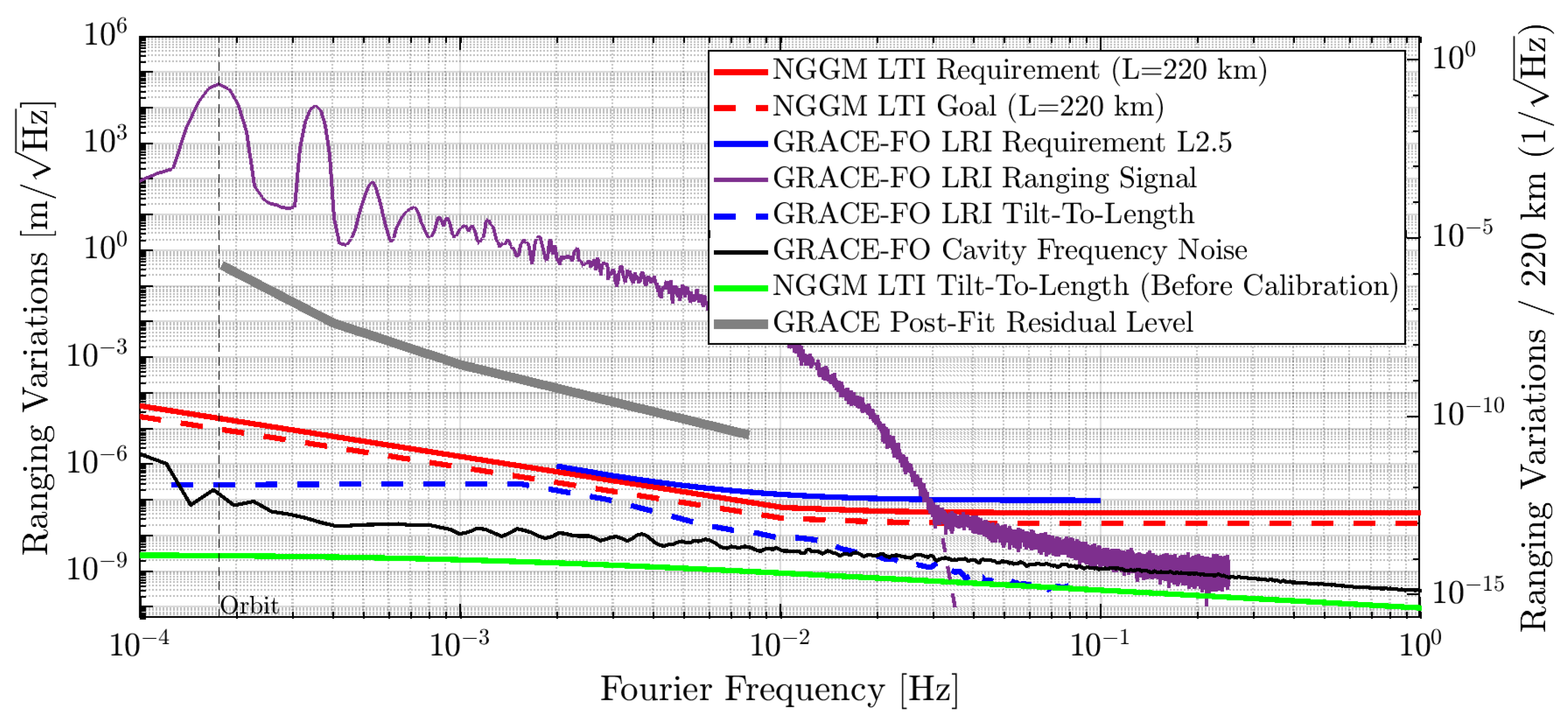
The key science performance requirement for the LTI was the ranging noise in the science measurement band, ranging from 0.1 mHz to 1 Hz.
Figure 3 gives an overview of the measured ranging signal of the LRI on GRACE-FO (purple) in comparison to the NGGM LTI and GRACE-FO requirements and performances. The ranging noise requirement of GRACE-FO was depicted in solid blue, the LRI tilt-to length noise term was shown in dashed blue and the cavity frequency noise in black (ground-based measurement before launch).
The NGGM LTI ranging noise requirement and goal and the expected tilt-to-length coupling were drawn in red and green.
The NGGM LTI had an extended science measurement band requirement down to 0.1 mHz and a stricter ranging noise requirement over the full frequency range. The improved performance was mainly expected to be enabled by a better performance of the satellite platform in terms of the pointing noise, which coupled via tilt-to-length coupling into the ranging noise and an improved thermal noise environment, specifically in the low-frequency region. It was foreseen that the fly would improve the accelerometers on the NGGM to benefit from the improved laser ranging performance, as the accelerometer performance on GRACE FO (and background model errors) was currently limiting the post-fit residuals.
For a more detailed discussion of the LTI related to the NGGM requirements, the satellite environmental requirements and the LTI performance analysis, please refer to [
19]. Below, we focused on a more detailed description of the individual units that formed the LTI.
3. LTI Units
One noticeable feature of the LTI was (similar to the LRI on GRACE-FO) that there was not a single platform–instrument separation, but the individual instrument units were distributed as separate elements within the spacecraft, in accordance with their different needs on the alignment, thermal noise and their thermal dissipation. The optical bench and the retroreflector required a placement with high angular and lateral accuracy and low thermal noise, and the optical cavity required a low thermal noise, but had no alignment requirements. The laser required a very narrow temperature range and the instrument control unit featured a rather high heat dissipation. In fact, the NGGM satellite platform and its payloads formed a highly integrated system necessary to achieve the demanding overall performance. In the following, we gave a description of the LTI units with their functions, challenges and development status.
3.1. Instrument Control Unit (ICU)/Phasemeter
The ICU constitutes the core digital signal processing and control unit of the LTI. The ICU’s primary function is to extract nanometer-stable translation and nanoradian-stable tilt measurements from the interferometric signals of the two optical beams superimposed on the optical bench. Gravity field information was encoded as tiny phase fluctuations in the translation measurements, which was filtered, decimated and formatted in science packets by using the ICU before streaming to the on-board-computer (OBC) for downlink and on-ground data post-processing afterwards.
The pitch and yaw tilt measurements based on the DWS signal were used in-flight to point the laser beam to the remote spacecraft with high precision, either in a fast steering mirror control loop [
21,
22] or by actuating the whole satellite platform.
The ICU was also incorporated as the function to lock the laser head to a Fabry–Pérot Cavity resonance by implementing a Pound–Drever–Hall (PDH) scheme [
23], in which the phase measurement was implemented via self-heterodyning the back-reflected light with spectral sidebands on the light coupled into the cavity. These sidebands were imprinted via phase modulation in a dedicated electro-optical modulator. This allowed to suppress the laser frequency noise of the LTI down to the requirement described in [
19].
To keep a stable optical link performance, and after conducting the laser link acquisition procedures [
19,
24], the ICU on the transponder satellite fed back the beat note phase information into an internal frequency controller. The controller actuated the laser internal piezo actuator and thermal loops in a laser offset phase-locking scheme, operating the transponder laser head with a configurable loop bandwidth of, typically, 10 kHz [
25,
26].
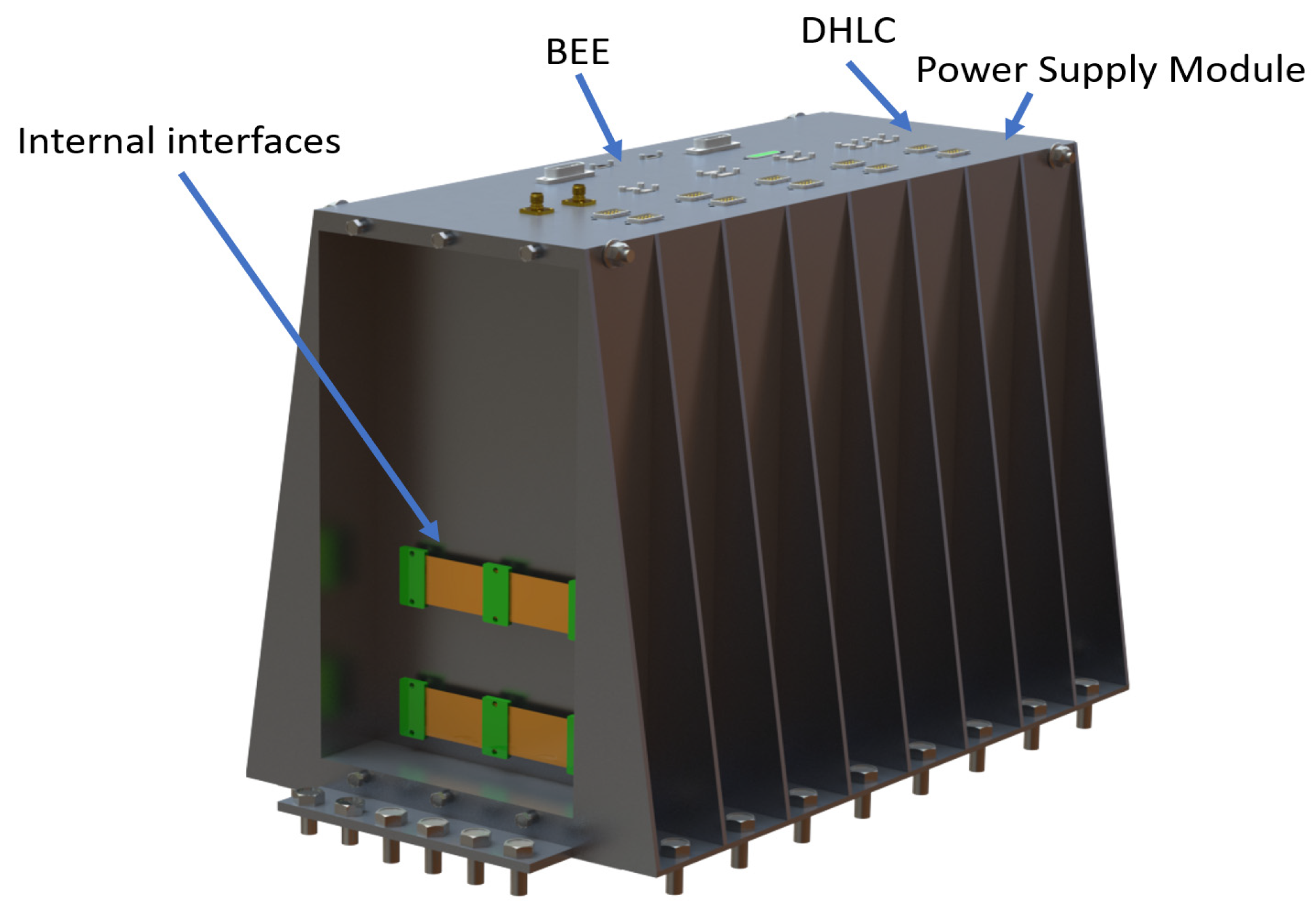
Figure 4 shows the baseline design of the physical assembly of the ICU architecture with its different modules, all-including internal redundancy for a high unit reliability over the mission’s lifetime. The ICU consisted of three mechanical frames, housing the following electronics:
Back-End Electronics (BEE). It houses three major features, the optical bench electronics (OBEs), the cavity lock electronics and the phasemeter digital core electronics. The OBEs implemented the variable gain controllers and anti-aliasing filters to adapt the quadrant photo receiver output signals to the optimum voltage levels required by the analog-to-digital converters. The OBEs also implemented fast-steering mirror control electronics with a two-axis readout and control signals for motor actuation for beam pointing to the remote S/C. The cavity lock electronics implemented the signal conditioning electronics, digitization and actuation electronics for the optical cavity lock control. The phasemeter digital core electronics implemented the digital signal core processing of all fast-digital control loops with stringent requirements in latency based on an FPGA core (e.g., digital phase-locked loops for an interferometric amplitude and phase readout, Pound–Drever–Hall logic for cavity-lock control and fast Fourier transform to support laser link acquisition procedures). It also implemented diagnostic functions for temperature monitoring and debugging functions.
Data Handling and Laser Control Module. It housed two major boards, the instrument control module (ICM) and the laser monitoring and control electronics. The ICM implemented the microprocessor capabilities for unit operation, timing, synchronization and communication with the platform, as well as digital control for laser offset phase locking. The ICM board also managed diagnostic functions for temperature monitoring of the laser. The laser monitoring and control implemented functions such as an ON/OFF switch, optical power monitoring and diagnostics.
Power Supply Module (for power supply and internal distribution to ICU modules). This electronic device received a power supply from the satellite platform. In addition, it provided internal power distribution to the ICU modules, as well as delivering the power supply to other LTI sub-systems such as quadrant photoreceivers and the steering mirror, laser and laser stabilization unit.
The development of precision laser ranging processors, or, in short, phasemeters, that was included in the BEE was pursued by the ESA and DLR for several years in the frame of the LISA mission [
27]. The most critical functions and performance aspects of the phasemeter units were already proven in hardware, supported by technology development activities initiated by the ESA [
28,
29].
Nowadays, this development is running towards a TRL6 unit demonstrator [
30], in which the NGGM mission benefits from previous realizations. With respect to the NGGM, a TRL of four is currently being assessed, allowing for a reasonably fast development of the ICU towards TRL6.
3.2. Laser Head Unit
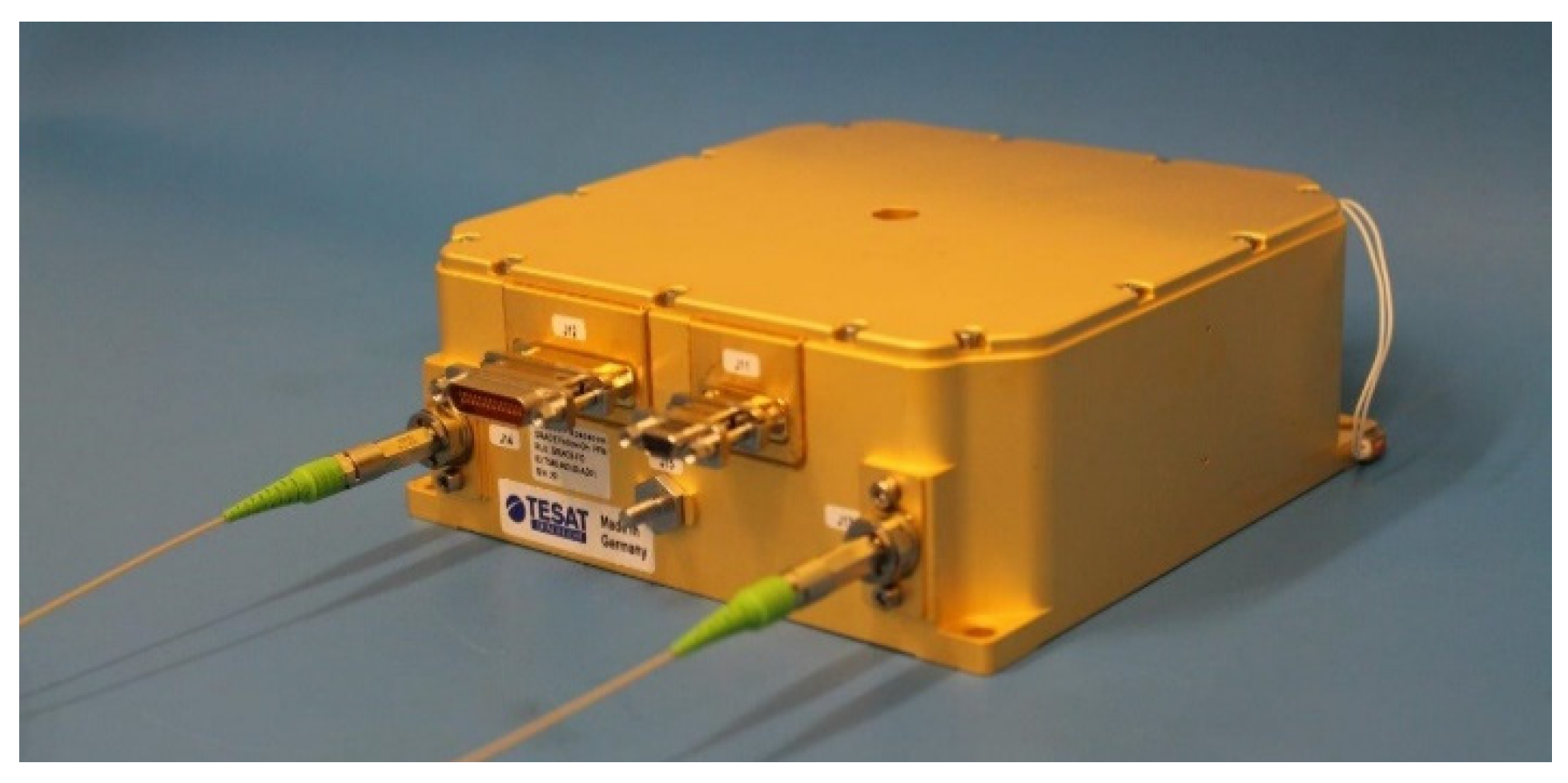
The laser head unit for the NGGM LTI was the reference laser unit (RLU) from TESAT Spacecom. The RLU is a space-qualified, fiber-coupled, low-noise, single-frequency, solid-state laser system with control electronics. It provided 25 mW of polarized optical output power at 1064 nm in a single-mode polarization, maintaining fiber to the optical bench, and was connected to the cavity via a second fiber output. A dedicated telemetry and telecommand (TM/TC) interface facilitated control of the system.
It is routinely used in the European data relay system (EDRS), and also in the LRI on GRACE-FO, and has demonstrated excellent performance and reliability throughout many missions, including LISA pathfinder [
31].
Figure 5 shows the RLU.
The laser was based on a non-planar ring oscillator (NPRO) and was internally partially redundant with respect to the pump laser modules. It achieved the required frequency noise performance when locked to the cavity/laser stabilization unit. The TRL of the RLU with respect to NGGM was assessed with TRL 6, formally limited by the increased mechanical launch loads expected for the NGGM compared to the heritage missions.
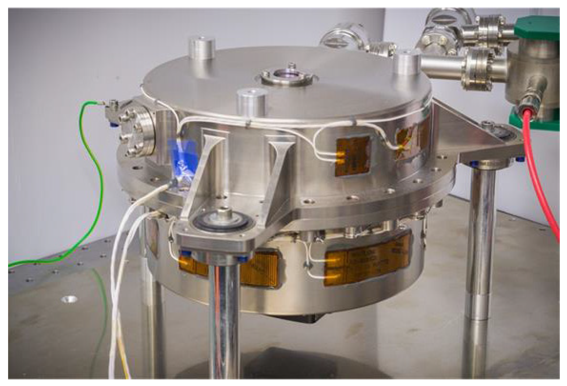
3.3. Laser Stabilization Unit
The laser stabilization unit was based on an optical Fabry–Pérot cavity. The baseline cavity for the NGGM was the ‘optical stabilizing reference cavity’ (OSRC), being developed within the ESA since 2017 within a multi-national European consortium led by Airbus. The OSRC activity aims for a cavity-based laser stabilization system based on an optical cubic cavity for the NGGM mission in the first project phase (1064 nm, cavity one) and for an optical lattice clock system in space (1397 nm, cavity one) in the second project phase.
The OSRC project aims to raise the TRL of core units to TRL 5–6, setting the basis for the advancement towards a flight-ready design in future activities. The laser frequency stability requirement for the NGGM system noise spectral density was (40 Hz)/√Hz √(1 + ((10 mHz)/f)2) for 0.1 mHz < f < 1 Hz, which was compatible with the only flight-ready cavity system currently available by Ball Aerospace that was used by the LRI on GRACE-FO.
The core of the OSRC LSU system was a highly stable optical cavity (designed by NPL) with its longitudinal Eigen modes serving as frequency references. The feedback signal was generated via the Pound–Drever–Hall scheme with the cavity lock electronics of the ICU.
The LSU system could be divided into the following building blocks:
The high stability and narrow linewidth of the LHU were derived from a cubic ultra-stable optical spacer using an ULE spacer of 5 cm in length with a coefficient of thermal expansion below 1 × 10⁻⁸/K near room temperature. Mirrors with fused silica substrate and crystalline coatings were optically contacted to the spacer. Mono-crystalline AlxGa1-xAs multilayer hetero-structures used as mirror coatings showed a Brownian noise contribution roughly an order of magnitude below that of typical dielectric mirrors. The substantial reduction in thermal noise from the mirrors enabled a significant improvement in the overall frequency stability of the optical reference cavities, pushing the ultimate boundaries of linewidth and noise performance that can be achieved in stabilized laser systems.
In terms of TRL, the LSU was assessed with six others for the cavity core and four for the optical arm that performs the connection between the optical fiber coming from the LHU and the optical cavity itself.
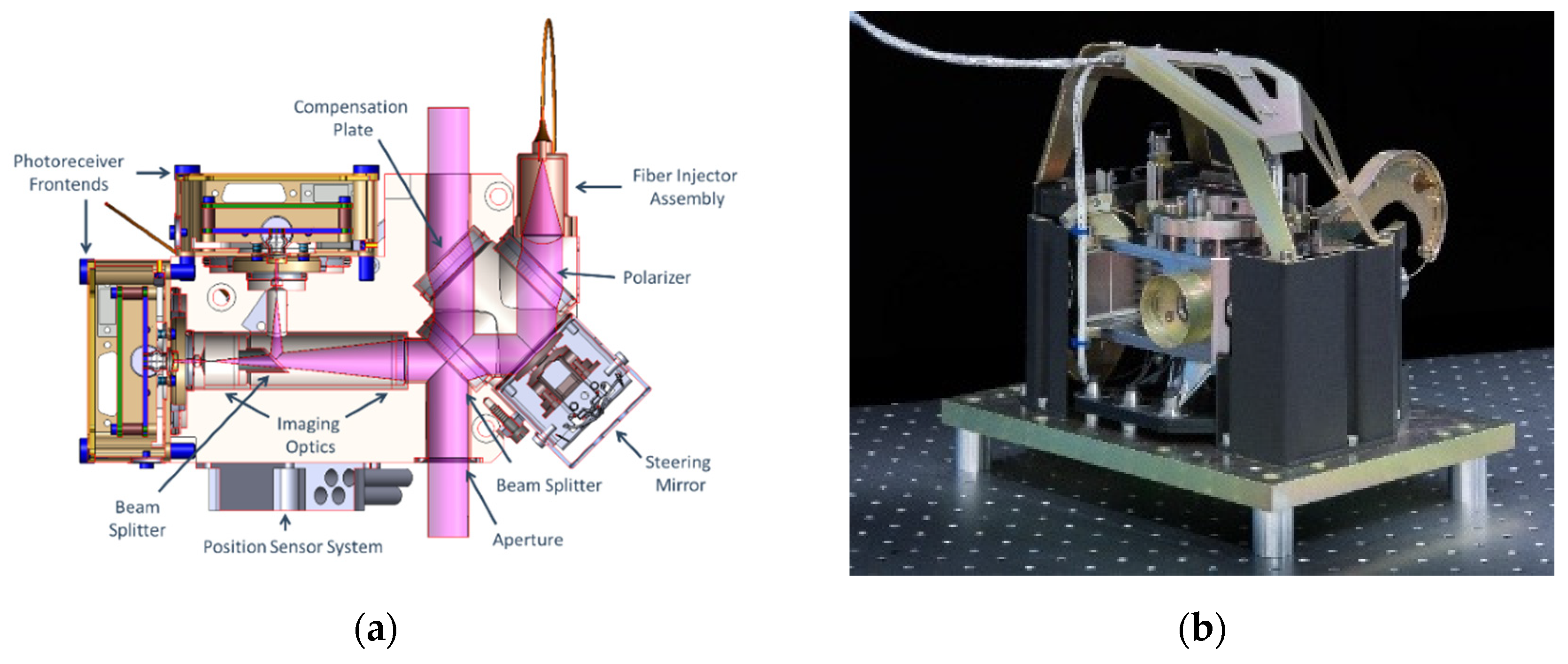
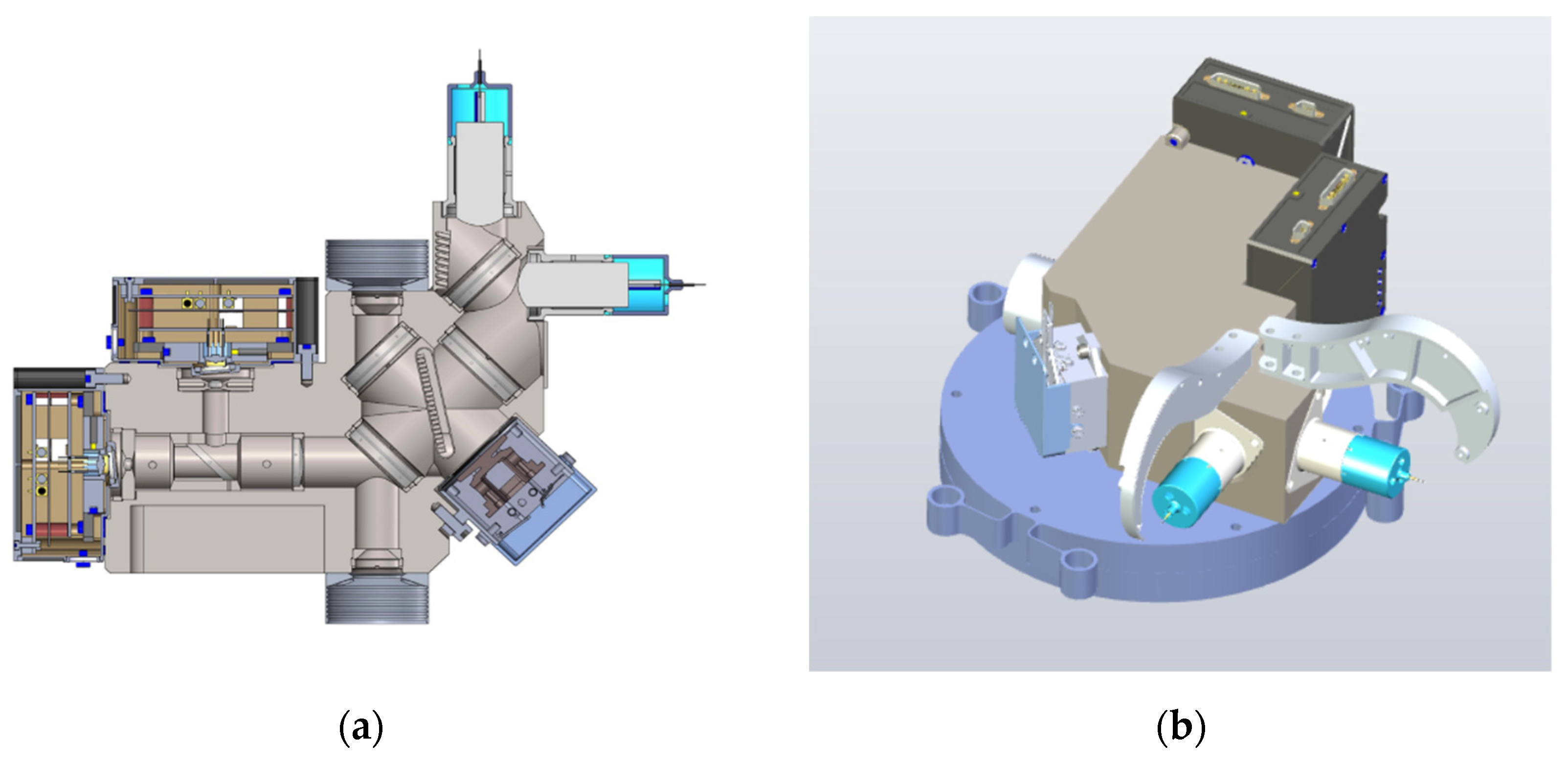
3.4. Optical Bench Assembly (OBA)
The optical bench hosted the majority of the free space interferometer optics. It incorporated the fiber-to-free space interface of the laser, optical elements for beam clean-up, shaping, routing and splitting of the laser light, as well as the FSM and two-quadrant photo receivers. To achieve the required highly stable interferometric measurement between the local oscillator and the received beam from the other spacecraft, the optical bench had several key features, including:
Beam steering: The OBA fine steering mirror allowed the LTI to counter any satellite pointing error with microradian accuracy. Control of the mirror was performed on the basis of the DWS error signal with the ICU.
Beam walk compensation and ranging noise compensation: The OBA entrance aperture and the steering mirror surface were imaged onto the detector plane of the quadrant photoreceivers (QPRs), thereby avoiding any beam walk and aperture diffraction effects on the quadrant photoreceivers. Furthermore, a “compensation plate” was introduced to significantly reduce angular coupling into the ranging measurement.
Equally important were a very good absolute wavefront planarity of λ/12 (
p-
v) over two times the Gaussian beam diameter, a high multipath suppression and a high pointing stability. To achieve this, special care was put into the CTE (coefficient of thermal expansion)-compensated low-stress mounts, optical surfaces vertical to the beam were avoided and critical optics have well-defined, non-zero wedge angles (see
Figure 8). For all but one (the second beam splitter) internal optical components, no fine adjustment was needed, significantly reducing the integration effort and increasing the robustness of the structure. The approach achieved a high thermal noise suppression (due to the high thermal mass enclosing the components) and high beam pointing stability (due to the symmetry of the titanium body with respect to the plane containing the beam). The optical components were mostly out of BK7G18, which matched the CTE to titanium well, further improving the thermo-optical stability of the OBA. The only elements that required precise alignment were the beam collimators, called fiber injector assemblies (FIAs), which were ultra-stable fully monolithic designs, in which the fiber was directly spliced to the collimator lens and the quadrant photoreceivers. The FIAs were aligned in an angle with shim rings and in a lateral position with micrometer screws (which were the ground support equipment). The QPRs were aligned in a longitudinal position with shim rings and in a lateral position again with micrometer screws, which were the ground support equipment and were later removed.
The difference between the GRACE-FO OBA and the NGGM OBA(s) was related mainly to the evolution from an experimental interferometer to the main instrument, leading to a required increase in lifetime, reliability and mechanical loads.
Figure 9 shows the current CAD design status of the NGGM OBA with redundant FIAs and an updated mechanical interface.
The optical bench for the NGGM LTI was based on the design developed for the GRACE-FO LRI, which has been successfully operating in orbit for more than 4 years by now. The heritage of the design was considered high, and the focus on the current development activities lay on the redundant FIAs and the verification of the suitability of the updated mechanical interface.
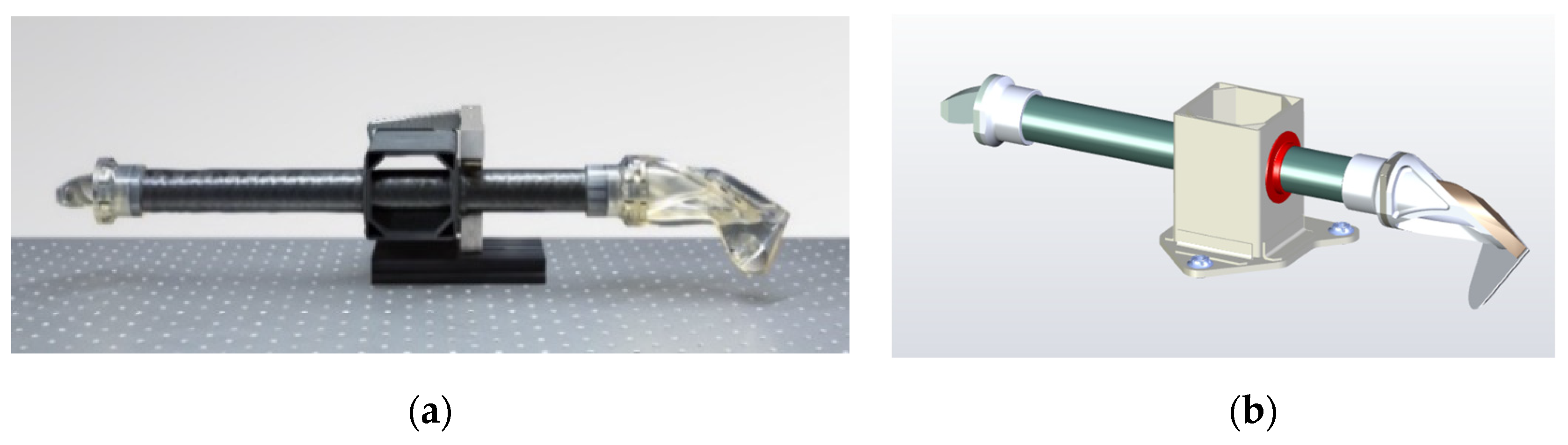
3.5. Retroreflector Unit (RRU)
The retroreflector unit consisted of an off-axis three-mirror retroreflector with its vertex located in the satellite center of mass. It routed the transmitted beam from the optical bench to the other spacecraft. Placing the vertex of each RRU at the satellite CoM enabled the LTI to measure the distance variation of the CoM of the two satellites to a nanometer accuracy without the need to actually have a physical mirror in the CoM, which is usually occupied by the accelerometer test mass.
Key requirements for the RRU were a beam co-alignment error of less than half the beam divergence (the requirement placed on the RRU was 40 µrad), a wavefront distortion of less than λ/15 per surface over two times the beam diameter and an optical path length change/vertex movement of less than some hundred nm/K.
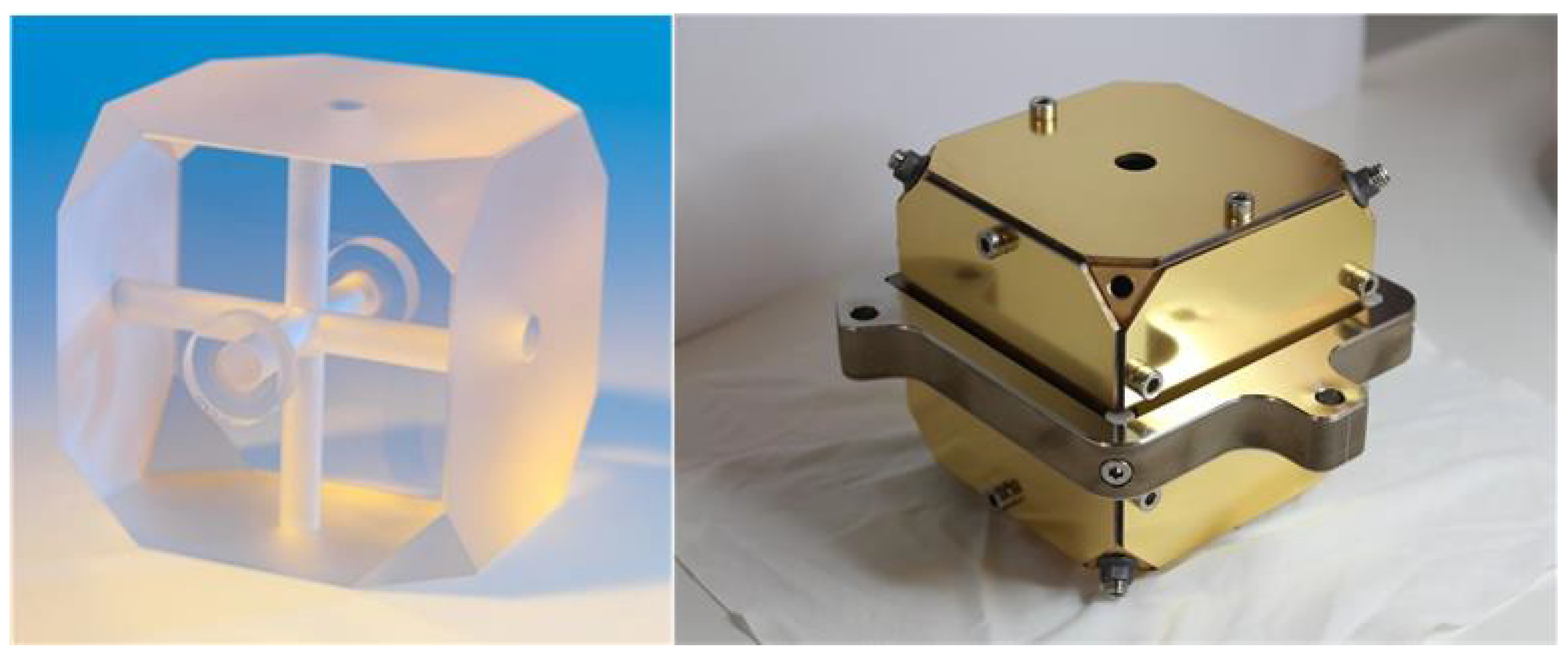
In GRACE-FO, the lateral beam separation required of the retroreflector was 600 mm, driven by the diameter of the cold gas tank. For the NGGM, the beam separation would likely be in the order of 500 mm.
Figure 10a shows, for reference, the RRU of the GRACE-FO LRI, consisting of a highly stable lightweight hybrid structure comprising a carbon-fiber (CFRP) and titanium frame and two bonded zerodur mirror assemblies. While this design met all optical performance requirements of the LTI, it would be subjected to higher environmental loads on the NGGM than one GRACE-FO. An adaptation of the design was, thus, necessary to mitigate the higher loads, in addition to implementing a different beam separation and mounting interface. The concept of the modified RRU is shown in
Figure 10b.
The RRU at first glance is a relatively simple structure, but it is not. To achieve the demanding co-alignment and ranging performance over the full mission duration, stringent requirements were placed on the CFRP tube with respect to the CTE homogeneity, the twist and tilt of the tube endfaces with a moisture release and temperature variation, the CFRP-to-zerodur interface stability, as well as on the zerodur-to-zerodur interfaces.
To achieve the CTE homogeneity, twist and tilt of the CFRP, the basic CFRP layer design both needed to be specifically optimized and special care had to be taken to ensure that the fiber–matrix ratio was kept homogeneous over the diameter. The CFRP-to-zerodur interfaces needed to be CTE-compensated to avoid thermal stress, leading to tilting, surface deformation and potentially cracking. The zerodur-to-zerodur interfaces (seven in total) were all optically contacted and, then, after the required alignment accuracy was achieved through the iteration of the optical contacting and potentially re-polishing, they were reinforced by injecting glue in dedicated glue pockets in the optically contacted surfaces. This approach enabled to meet the challenging co-alignment and ranging noise requirements of the overall structure and survive the launch loads.
With the GRACE-FO heritage, where this technology was successfully applied and is still working perfectly in orbit, a TRL of six was assessed. The design modifications focused on the different beam spacing, the higher launch loads as well as the fine-tuning of the various interfaces.
4. Instrument Options and Next Steps
In addition to the core LTI units described above, several instrument options are currently being discussed. Most prominently, these are the inclusions of an absolute frequency reference and additional functions via the optical link.
4.1. Scale Factor Measurement System
As mentioned in
Section 2, knowledge of the absolute laser frequency was required to transfer the laser phase measurements into actual ranging measurements. In GRACE-FO, the laser ranging instrument (LRI) measurement was referenced to the microwave ranging instrument (MWI), which was stabilized to the ultra-stable oscillator (USO). The USO frequency was measured with high accuracy during a GPS-based orbit and clock error determination. The observed variations in differential LRI and MWI scales in GRACE-FO exhibited variations of approximately 0.2 ppm, corresponding to approximately 60 MHz, and likely absorbed tone errors from both of the instruments. For the NGGM, where there would be no MWI, the absolute frequency had to be derived differently, potentially down to 0.01 ppm, to meet the tightened performance requirements. Several alternatives are currently being studied, including the derivation of the scale factor through post-processing or a dedicated scale factor measurement system, such as a scale factor unit in addition to the LSU, measuring the cavity-free spectral range as described in [
1], an iodine spectroscopy unit or even a (relatively low-performance) frequency comb. The TRL of the SFMS is, depending on the technology assessed as TRL2–4 and a trade-off between different options, currently ongoing.
4.2. Optical Signal Transmission
Adding pseudo-random noise codes to the laser light as a weak phase modulation via an electro-optical modulator (EOM) allowed to measure the absolute range between the S/C to a cm accuracy, the offset between their on-board clocks to µs accuracy and the bi-directional transmission of data with a rate of several 10 kbit/s. While not strictly required for the core NGGM function, this would provide additional flexibility, robustness and redundancy in operation and serve as a technology demonstration for LISA (where these functions are required) and other missions. Those functions and their performance have been demonstrated in laboratory [
32], and are under development for LISA right now.
4.3. Next Steps
The currently running LTI pre-development aims at developing of key LTI units to TRL5 or 6, sufficient for mission adoption in 2023. With the details of a potential cooperation between the ESA and NASA on the LTI not being defined, this means that the instrument control units and the laser stabilization unit are also being developed in Europe towards TRL6 for a potential purely European LTI. This includes the realization of EM-like units, with which critical parameters can be verified in a relevant environment. Therefore, design work is currently ongoing, mainly for the ICU, LSU, OBA and SFMS, while the RRU work is focusing on the overall concept. In parallel, we are supporting the currently running parallel phase A mission studies of Thales Alenia Space, Italy, and Airbus DS, Germany, to ensure the compatibility of both platform concepts with the LTI.
5. Conclusions
Gravity missions, such as GOCE, GRACE and GRACE-FO, provide essential data to monitor Earth’s system, specifically valuable in our aim to better understand the mechanisms of climate change. The precise tracking of the distance between pairs of satellites is key to provide required data, and the technology to enable this by means of laser interferometry is currently under development. The technology demonstrator of the laser ranging interferometer on GRACE-FO already works extremely well in orbit, since more than 4 years have passed with very few interruptions and far superior ranging performance compared to the microwave ranging instrument.
Future missions, such as the NGGM, aim to significantly improve performance by combining the improved ranging performance of the laser interferometry with improved accelerometers and platform performance, and ideally the implementation of at least two pairs of satellites. The transfer of the laser ranging interferometer from a technology demonstrator to a main instrument with higher performance and reliability is pursued by the ESA with the pre-development activity of the so-called laser tracking instrument—LTI. In addition, independent from the current programmatic baseline, which foresees work share between Europe and the US with hardware contributions from both sides to both satellite pairs, the aim of this activity is also to gain the capability to implement the LTI with only European suppliers for all units in case it should be needed.
After a detailed trade between different instrument concepts over recent years, the off-axis transponder concept LTI was selected for the NGGM. With the existing implementation of this concept as a demonstrator on GRACE-FO, a lot of knowledge and technology are already available. The requirements and required technologies for the mission and the individual units are well understood, enabling a clear development plan towards implementation in the NGGM.
On GRACE-FO, the tilt-to-length coupling, the thruster shocks and the absolute laser frequency knowledge (relevant to derive the scale factor between the phase and range) limited the performance of the LRI. For the NGGM, it is, therefore, foreseen that the tilt-to-length coupling needs to be reduced with a reduced satellite pointing noise and tilt-to-length calibration of the LTI. Linear thrusters would eliminate the thruster shocks and the absolute laser frequency knowledge is foreseen to be improved by an order of magnitude either by using a dedicated scale factor measurement system or dedicated post-processing. With these modifications the LTI is expected to meet all NGGM mission requirements.
The unit level design as well as the LTI system engineering activities are progressing in accordance with the timeline of potential mission prime contractors. The focus of the development of the units, which we already provided for GRACE-FO, lies in the necessary modifications for increased reliability and mechanical loads. Increased redundancies, be it full redundancy on a unit level, as foreseen in the fully redundant LTI configuration or partial redundancy, e.g., with respect to photoreceivers, beam collimators and steering mirror electronics on the optical bench, as well as increased parts quality for some electronics, were considered and implemented in the design. The intent was to keep what worked well on GRACE-FO and limit the modifications to what was needed for reliability and changed the mechanical loads. The ICU design was based on the LISA developments and was a newly developed unit for the NGGM. The laser remained the same as that used for GRACE-FO, with minor internal modifications. The foreseen laser stabilization unit was from the OSRC development, which ran in parallel. The least developed instrument unit was the scale factor measurement system, but with several options identified to provide the required functionality, this development was also expected to be fulfilled with “standard engineering” without extraordinary risks with respect to the currently running phase A and LTI pre-development activities.
Having stated all that, the task to measure the changes in the inter-satellite distance to some nm/√Hz still remains a challenging task, and requires a careful design and execution of manufacturing, integration and testing, not only of the LTI, but also the other payload elements, such as the accelerometers and the whole satellite platform.
Author Contributions
Conceptualization, K.N., A.F., M.K., C.D., B.A.C., A.B., V.M., G.H. and J.J.E.D.; Data curation, K.N. and M.W.; Formal analysis, K.N., A.F., M.K., C.D., M.H., B.A.C., A.B., J.F., M.W., V.M., G.H., M.M. and J.J.E.D.; Investigation, K.N., K.V., A.F., M.K., C.D., M.H., B.A.C., A.B., J.F., V.M., G.H., M.M. and J.J.E.D.; Methodology, K.N.; Project administration, K.V. and A.F.; Validation, M.H.; Visualization, K.N., B.A.C. and A.B.; Writing—original draft, K.N., V.M., G.H. and J.J.E.D.; Writing—review and editing, K.N., K.V., M.K., C.D., V.M., G.H. and M.M. All authors have read and agreed to the published version of the manuscript.
Funding
This research was funded by the European Space Agency (ESA), by the activity “Pre-development of a Laser Tracking Instrument”,contract no. 4000134527/21/NL/AD. The view expressed herein can in no way be taken to reflect the official opinion of the European Space Agency. This work, or some authors, were supported by: The Deutsche Forschungsgemeinschaft (DFG, German Research Foundation, project-ID 434617780, SFB 1464) and Clusters of Excellence “QuantumFrontiers: Light and Matter at the Quantum Frontier: Foundations and Applications in Metrology” (EXC-2123, project number: 390837967).
Conflicts of Interest
The authors declare no conflict of interest.
References
- Pail, R.; Bruinsma, S.; Migliaccio, F.; Förste, C.; Goiginger, H.; Schuh, W.D.; Höck, E.; Reguzzoni, M.; Brockmann, J.M.; Abrikosov, O.; et al. First GOCE gravity field models derived by three different approaches. J. Geod. 2011, 85, 819–843. [Google Scholar] [CrossRef] [Green Version]
- Dahle, C.; Murböck, M.; Flechtner, F.; Dobslaw, H.; Michalak, G.; Neumayer, K.H.; Abrykosov, O.; Reinhold, A.; König, R.; Sulzbach, R.; et al. The GFZ GRACE RL06 monthly gravity field time series: Processing details and quality assessment. Remote Sens. 2019, 11, 2116. [Google Scholar] [CrossRef] [Green Version]
- Landerer, F.W.; Flechtner, F.M.; Save, H.; Webb, F.H.; Bandikova, T.; Bertiger, W.I.; Bettadpur, S.V.; Byun, S.H.; Dahle, C.; Dobslaw, H.; et al. Extending the global mass change data record: GRACE Follow-On instrument and science data performance. Geophys. Res. Lett. 2020, 47, e2020GL088306. [Google Scholar] [CrossRef]
- Ciracì, E.; Velicogna, I.; Swenson, S. Continuity of the mass loss of the world’s glaciers and ice caps from the GRACE and GRACE Follow-On missions. Geophys. Res. Lett. 2020, 47, e2019GL086926. [Google Scholar] [CrossRef]
- Chen, J.; Tapley, B.; Wilson, C.; Cazenave, A.; Seo, K.W.; Kim, J.S. Global ocean mass change from GRACE and GRACE Follow-On and altimeter and Argo measurements. Geophys. Res. Lett. 2020, 47, e2020GL090656. [Google Scholar] [CrossRef]
- Eicker, A.; Forootan, E.; Springer, A.; Longuevergne, L.; Kusche, J. Does GRACE see the terrestrial water cycle “intensifying”? J. Geophys. Res. Atmos. 2016, 121, 733–745. [Google Scholar] [CrossRef] [Green Version]
- Kornfeld, R.P.; Arnold, B.W.; Gross, M.A.; Dahya, N.T.; Klipstein, W.M.; Gath, P.F.; Bettadpur, S. GRACE-FO: The Gravity Recovery and Climate Experiment Follow-On Mission. J. Spacecr. Rocket. 2019, 56, 931–951. [Google Scholar] [CrossRef]
- Sheard, B.S.; Heinzel, G.; Danzmann, K.; Shaddock, D.A.; Kliptein, W.M.; Folkner, W.M. Intersatellite laser ranging instrument for the GRACE follow-on mission. J. Geod. 2012, 86, 1083–1095. [Google Scholar] [CrossRef]
- Abich, K.; Abramovici, A.; Amparan, B.; Baatzsch, A.; Okihiro, B.B.; Barr, D.C.; Bize, M.P.; Bogan, C.; Braxmaier, C.; Burke, M.J.; et al. In-Orbit Performance of the GRACE Follow-On Laser Ranging Interferometer. Phys. Rev. Lett. 2019, 123, 031101. [Google Scholar] [CrossRef] [Green Version]
- Bender, P.L.; Wiese, D.; Nerem, R.S. A Possible dual-grace mission with 90 degree and 63 degree inclination orbits. In Proceedings of the 3rd International Symposium on Formation Flying, Missions and Technologies, ESA/ESTEC, Noordwijk, The Netherlands, 23–25 April 2008; pp. 1–6. Available online: https://www.worldcat.org/title/proceedings-of-the-3rd-international-symposium-on-formation-flying-missions-and-technologies-23-25-april-2008-esa-estec-noordwijk-the-netherlands/oclc/809927086?referer=di&ht=edition (accessed on 27 July 2022).
- Pail, R.; Yeh, H.-C.; Feng, W.; Hauk, M.; Purkhauser, A.; Wang, C.; Zhong, M.; Shen, Y.; Chen, Q.; Luo, Z.; et al. Next-Generation Gravity Missions: Sino-European Numerical Simulation Comparison Exercise. Remote Sens. 2019, 11, 2654. [Google Scholar] [CrossRef] [Green Version]
- Gruber, T.; Panet, I.; E.motion2 Team. Proposal to ESA’s Earth Explorer Call 9: Earth System Mass Transport Mission-E.motion2. Deutsche Geodätische Kommission der Bayerischen Akademie der Wissenschaften, Reihe B, Angewandte Geodäsie, Series B. 2015. Available online: https://dgk.badw.de/fleadmin/user_upload/Files/DGK/docs/b-318.pdf (accessed on 27 July 2022).
- Pie, N.; Bettadpur, S.V.; Tamisiea, M.; Krichman, B.; Save, H.; Poole, S.; Nagel, P.; Kang, Z.; Jacob, G.; Ellmer, M.; et al. Time Variable Earth Gravity Field Models from the First Spaceborne Laser Ranging Interferometer. J. Geophys. Res. Solid Earth 2021, 126, e2021JB022392. [Google Scholar] [CrossRef]
- Flechtner, F.; Neumayer, K.H.; Dahle, C.; Dobslaw, H.; Fagiolini, E.; Raimondo, J.C.; Güntner, A. What can be expected from the GRACE-FO laser ranging interferometer for earth science applications? In Remote Sensing and Water Resources; Springer International Publishing: Cham, Switzerland, 2016; pp. 263–280. [Google Scholar] [CrossRef] [Green Version]
- Ghobadi-Far, K.; Han, S.C.; McCullough, C.M.; Wiese, D.N.; Yuan, D.N.; Landerer, F.W.; Sauber, J.; Watkins, M.M. GRACE Follow-On laser ranging interferometer measurements uniquely distinguish short-wavelength gravitational perturbations. Geophys. Res. Lett. 2020, 47, e2020GL089445. [Google Scholar] [CrossRef]
- Ghobadi-Far, K.; Han, S.C.; McCullough, C.M.; Wiese, D.N.; Ray, R.D.; Sauber, J.; Shihora, L.; Dobslaw, H. Along-orbit analysis of GRACE Follow-On inter-satellite laser ranging measurements for sub-monthly surface mass variations. J. Geophys. Res. Solid Earth 2022, 127, e2021JB022983. [Google Scholar] [CrossRef]
- Peidou, A.; Landerer, F.; Wiese, D.; Ellmer, M.; Fahnestock, E.; McCullough, C.; Spero, R.; Yuan, D.N. Spatiotemporal Characterization of Geophysical Signal Detection Capabilities of GRACE-FO. Geophys. Res. Lett. 2022, 49, e2021GL095157. [Google Scholar] [CrossRef]
- Behzadpour, S.; Kvas, A.; Mayer-Gürr, T. GRACE Follow-On Gravity Field Recovery from Combined Laser Ranging Interferometer and Microwave Ranging System Measurements. In Proceedings of the EGU General Assembly Conference Abstracts, Online, 19–30 April 2021; p. EGU21-9415. [Google Scholar] [CrossRef]
- Nicklaus, K.; Cesare, S.; Massotti, L.; Bonino, L.; Mottini, S.; Pisani, M.; Silvestrin, P. Laser metrology concept consolidation for NGGM. CEAS Space J. 2020, 12, 313–330. [Google Scholar] [CrossRef]
- Wegener, H.; Müller, V.; Heinzel, G.; Misfeldt, M. Tilt-to-Length Coupling in the GRACE Follow-On Laser Ranging Interferometer. J. Spacecr. Rocket. 2020, 57, 1362–1372. [Google Scholar] [CrossRef]
- Goswami, S.; Francis, S.P.; Bandikova, T.; Spero, E.R. Analysis of GRACE Follow-On Laser Ranging Interferometer derived inter-satellite pointing angles. IEEE Sens. J. 2021, 21, 19209–19221. [Google Scholar] [CrossRef]
- Heinzel, G.; Álvarez, M.D.; Pizzella, A.; Brause, N.; Delgado, J.J.E. Tracking-Length and Differential-Wave-Front-Sensing Signals from Quadrant Photodiodes in Heterodyne Interferometers with Digital Phase-Locked Loop Readout. Phys. Rev. Appl. 2020, 14, 054013. [Google Scholar] [CrossRef]
- Rees, E.R.; Wade, A.R.; Sutton, A.J.; Spero, R.E.; Shaddock, D.A.; McKenzie, K. Absolute frequency readout derived from ULE cavity for next generation geodesy missions. Opt. Express 2021, 29, 26014–26027. [Google Scholar] [CrossRef]
- Wuchenich, D.; Mahrdt, C.; Sheard, B.S.; Francis, S.P.; Spero, R.E.; Miller, J.; Mow-Lowry, C.M.; Ward, R.L.; Klipstein, W.M.; Heinzel, G.; et al. Laser link acquisition demonstration for the GRACE Follow-On mission. Opt. Express 2014, 22, 11351–11366. [Google Scholar] [CrossRef]
- Francis, S.P.; Lam, T.T.-Y.; McKenzie, K.; Sutton, A.J.; Ward, R.; McClelland, D.; Shaddock, D. Weak-light phase tracking with a low cycle slip rate. Opt. Lett. 2014, 39, 5251–5254. [Google Scholar] [CrossRef] [PubMed]
- Liao, A.; Ni, W.T.; Shy, J.T. Pico-Watt and Femto-Watt Weak-Light Phase Locking. Int. J. Mod. Phys. D 2002, 11, 1075–1085. [Google Scholar] [CrossRef]
- LISA Mission L3 Proposal. Available online: https://www.elisascience.org/files/publications/LISA_L3_20170120.pdf (accessed on 27 July 2022).
- Barke, S.; Brause, N.; Bykov, I.; Delgado, J.J.E.; Enggaard, A.; Gerberding, O.; Heinzel, G.; Kullmann, J.; Perdersen, S.M.; Rasmussen, T. LISA Metrology System. Available online: https://pure.mpg.de/rest/items/item_2058697_2/component/file_2058696/content (accessed on 27 July 2022).
- Gerberding, O.; Diekmann, C.; Kullmann, J.; Tröbs, M.; Bykov, I.; Barke, S.; Brause, N.C.; Delgado, J.J.E.; Schwarze, T.S.; Reiche, J.; et al. Readout for intersatellite laser interferometry: Measuring low frequency phase fluctuations of high-frequency signals with microradian precision. Rev. Sci. Instrum. 2015, 86, 074501. [Google Scholar] [CrossRef] [Green Version]
- Delgado, J.J.E.; Andersen, A.; Bykov, I.; Coutinho, D.; Dovale Alvarez, M.; Fernández Barranco, G.; Gerberding, O.; Guizzo, G.P.; Hornstrup, A.; Jessen, N.C.; et al. Optical phase readout instrument for picometer-level precision heterodyne interferometers. Sens. Transducers J. 2022, 247, 1–7. [Google Scholar]
- McNamara, P.; Racca, G. Introduction to LISA pathfinder, LISA-LPF-RP-0002, 30 March 2009. Available online: https://sci.esa.int/documents/34614/36035/1567257332401-LISA-LPFRP-0002.pdf (accessed on 27 July 2022).
- Delgado, E.; José, J. Laser Ranging and Data Communication for the Laser Interferometer Space Antenna. Ph.D. Thesis, Universidad de Granada, Granada, Spain, 2012. Available online: https://digibug.ugr.es/handle/10481/21038 (accessed on 27 July 2022).
| Publisher’s Note: MDPI stays neutral with regard to jurisdictional claims in published maps and institutional affiliations. |
© 2022 by the authors. Licensee MDPI, Basel, Switzerland. This article is an open access article distributed under the terms and conditions of the Creative Commons Attribution (CC BY) license (https://creativecommons.org/licenses/by/4.0/).


 ,
, 


