
A Novel Design and Development of a Strip-Fed Circularly Polarized Rectangular Dielectric Resonator Antenna for 5G NR Sub-6 GHz Band Applications

 ,
,  ,
,  , ,
, ,  , , and
Abstract
:1. Introduction
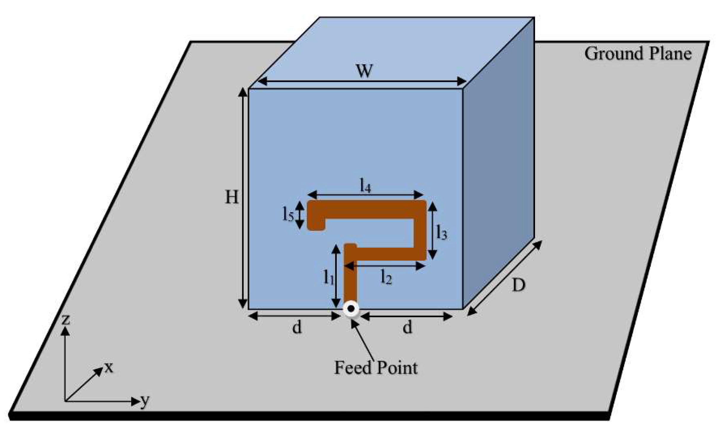
2. Antenna Geometry
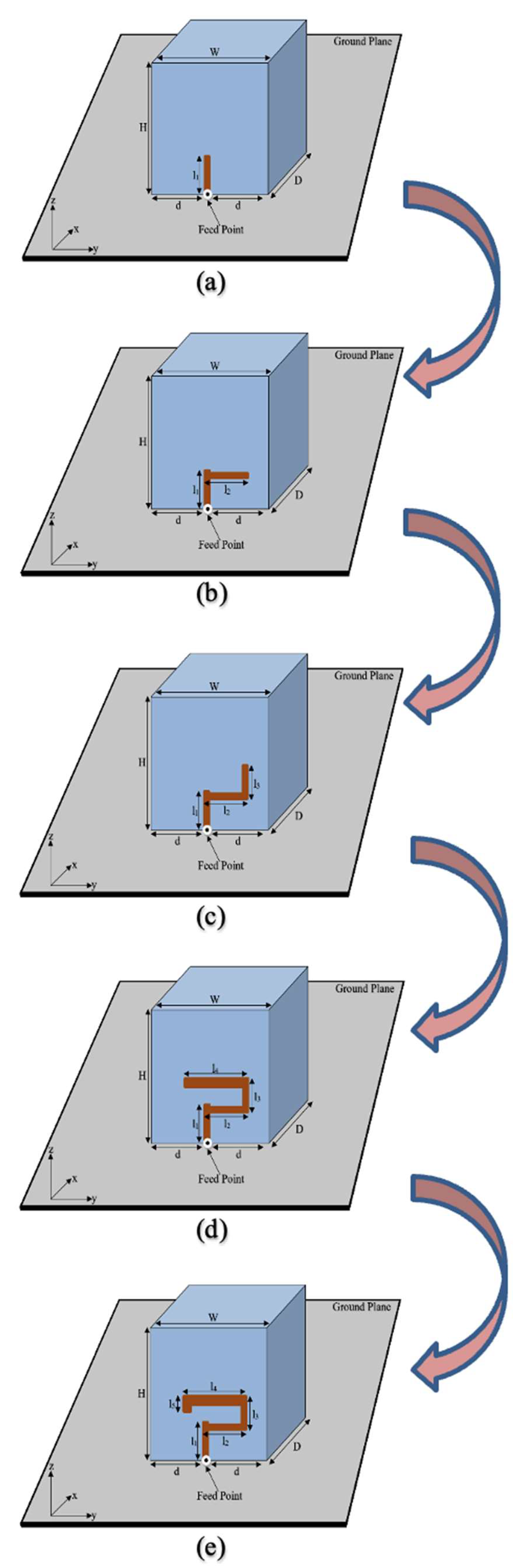
3. Circularly Polarized 5G Antenna Design and Optimization
3.1. Geometry 1
3.2. Geometry 2
3.3. Geometry 3
3.4. Geometry 4
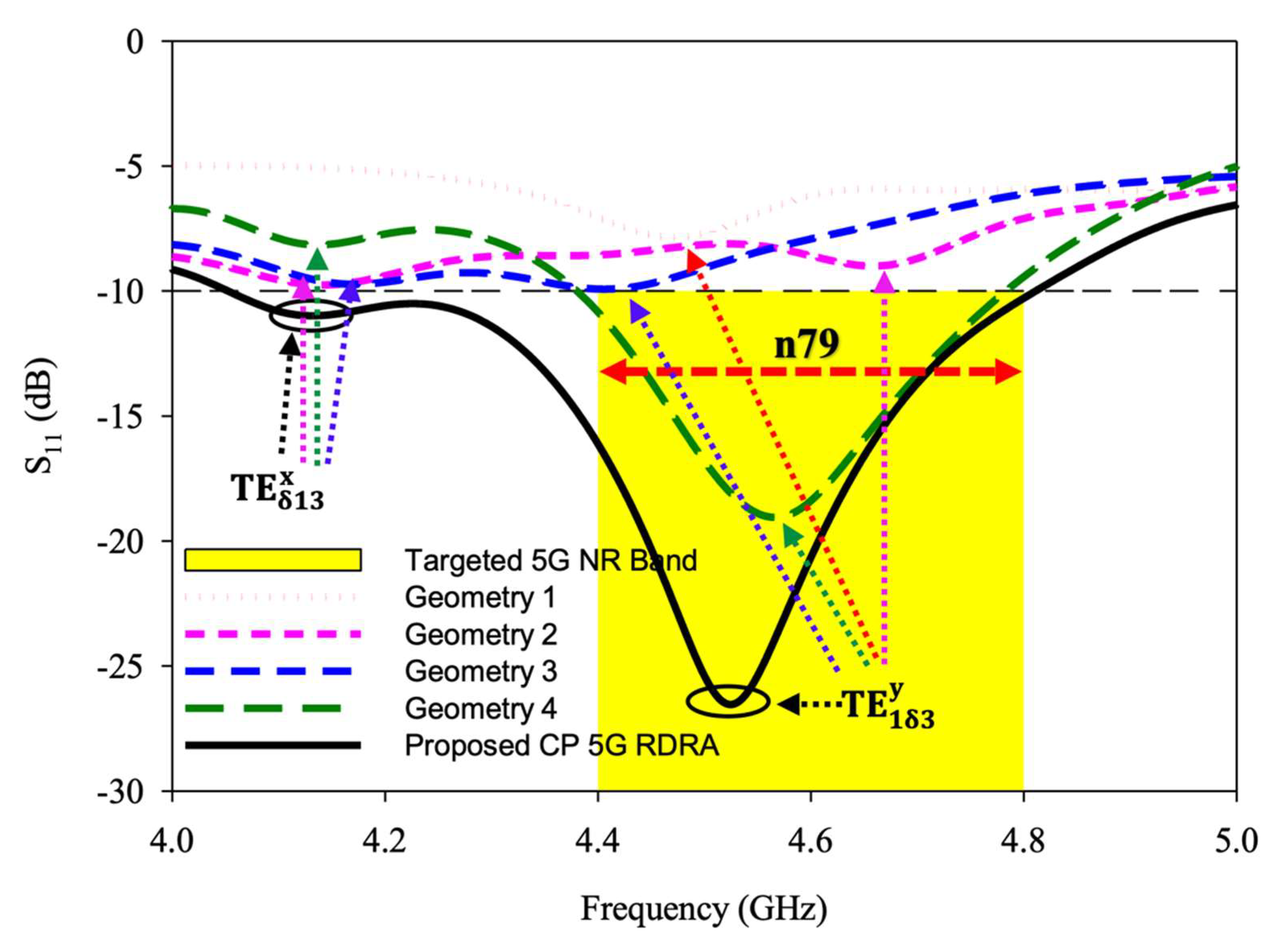
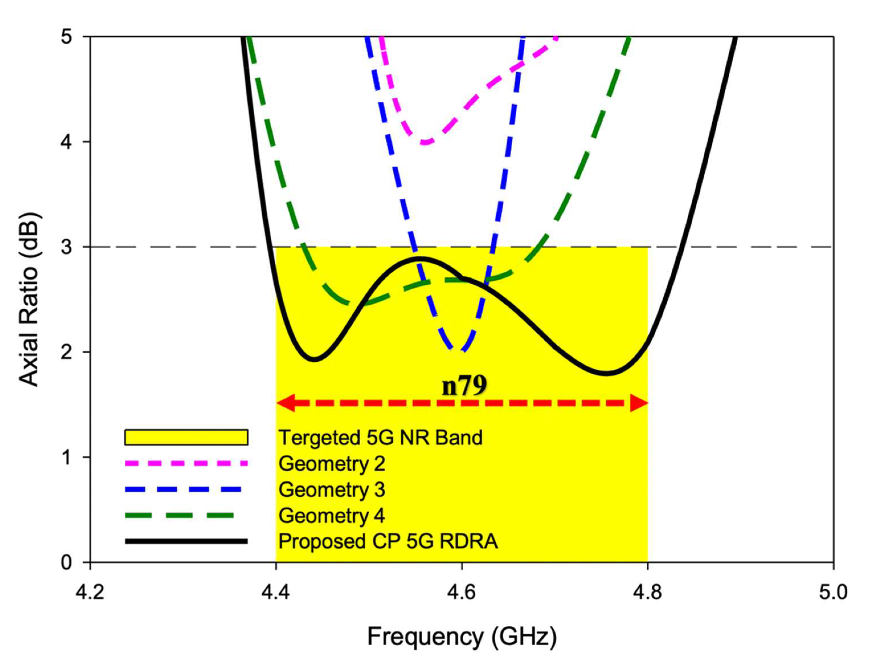
3.5. Geometry of the Proposed CP 5G RDRA
4. Measurement Results
5. Conclusions
Author Contributions
Funding
Institutional Review Board Statement
Informed Consent Statement
Data Availability Statement
Acknowledgments
Conflicts of Interest
References
- Rafique, U.; Khan, S.; Ahmed, M.M.; Kiani, S.H.; Abbas, S.M.; Saeed, S.I.; Alibakhshikenari, M.; Dalarsson, M. Uni-Planar MIMO Antenna for Sub-6 GHz 5G Mobile Phone Applications. Appl. Sci. 2022, 12, 3746. [Google Scholar] [CrossRef]
- Kiani, S.H.; Iqbal, A.; Wong, S.W.; Savci, H.S.; Alibakhshikenari, M.; Dalarsson, M. Multiple Elements MIMO Antenna System with Broadband Operation for 5th Generation Smart Phones. IEEE Access 2022, 10, 38446–38457. [Google Scholar] [CrossRef]
- Illahi, U.; Iqbal, J.; Sulaiman, M.I.; Alam, M.; Su’ud, M.M.; Khattak, M.I. Design and development of a singly-fed circularly polarized rectangular dielectric resonator antenna for WiMAX/Satellite/5G NR band applications. AEU Int. J. Electron. Commun. 2020, 126, 153443. [Google Scholar] [CrossRef]
- Chen, H.N.; Song, J.; Park, J. A Compact Circularly Polarized MIMO Dielectric Resonator Antenna over Electromagnetic Band-Gap Surface for 5G Applications. IEEE Access 2019, 7, 140889–140898. [Google Scholar] [CrossRef]
- Mukherjee, B.; Patel, P.; Mukherjee, J. A review of the recent advances in dielectric resonator antennas. J. Electromagn. Waves Appl. 2020, 34, 1095–1158. [Google Scholar] [CrossRef]
- Ahmad, Z.; Hesselbarth, J. On-Chip Dual-Polarized Dielectric Resonator Antenna for Millimeter-Wave Applications. IEEE Antennas Wirel. Propag. Lett. 2018, 17, 1769–1772. [Google Scholar] [CrossRef]
- Baldazzi, E.; Al-Rawi, A.; Cicchetti, R.; Smolders, A.B.; Testa, O.; van Coevorden Moreno, C.D.; Caratelli, D. A High-Gain Dielectric Resonator Antenna with Plastic-Based Conical Horn for Millimeter-Wave Applications. IEEE Antennas Wirel. Propag. Lett. 2020, 19, 949–953. [Google Scholar] [CrossRef]
- Mishra, N.K.; Das, S.; Vishwakarma, D.K. Beam steered linear array of cylindrical dielectric resonator antenna. AEU-Int. J. Electron. Commun. 2019, 98, 106–113. [Google Scholar] [CrossRef]
- Anuar, S.U.; Jamaluddin, M.H.; Din, J.; Kamardin, K.; Dahri, M.H.; Idris, I.H. Triple band mimo dielectric resonator antenna for lte applications. AEU-Int. J. Electron. Commun. 2020, 118, 153172. [Google Scholar] [CrossRef]
- Mazhar, W.; Klymyshyn, D.M.; Wells, G.; Qureshi, A.A.; Jacobs, M.; Achenbach, S. Low-Profile Artificial Grid Dielectric Resonator Antenna Arrays for mm-Wave Applications. IEEE Trans. Antennas Propag. 2019, 67, 4406–4417. [Google Scholar] [CrossRef]
- Iqbal, J.; Illahi, U.; Yasin, M.N.M.; Albreem, M.A.; Akbar, F.M. Bandwidth enhancement by using parasitic patch on dielectric resonator antenna for sub-6 GHz 5G NR bands application. Alex. Eng. J. 2022, 61, 5021–5032. [Google Scholar] [CrossRef]
- Boyuan, M.; Pan, J.; Wang, E.; Yang, D. Wristwatch-Style Wearable Dielectric Resonator Antennas for Applications on Limps. IEEE Access 2020, 8, 59837–59844. [Google Scholar] [CrossRef]
- Mongia, R.K.; Ittipiboon, A. Theoretical and experimental investigations on rectangular dielectric resonator antennas. IEEE Trans. Antennas Propag. 1997, 45, 1348–1356. [Google Scholar] [CrossRef]
- Mongia, R.K.; Ittipiboon, A.; Cuhaci, M.; Roscoe, D. Circularly polarized dielectric resonator antenna. Electron. Lett. 1994, 30, 1361–1362. [Google Scholar] [CrossRef]
- Leung, K.W.; Wong, W.C.; Luk, K.M.; Yung, E.K.N. Circularly polarised dielectric resonator antenna excited by dual conformal strips. Electron. Lett. 2000, 36, 484–486. [Google Scholar] [CrossRef]
- Wong, W.C.; Leung, K.W. Circularly polarized dielectric resonator antenna excited by dual conformal strips of unequal lengths. Microw. Opt. Technol. Lett. 2001, 29, 348–350. [Google Scholar] [CrossRef]
- Altaf, A.; Yang, Y.; Lee, K.-Y.; Hwang, K.C. Circularly polarized spidron fractal dielectric resonator antenna. IEEE Antennas Wireless Propag. Lett. 2015, 14, 1806–1809. [Google Scholar] [CrossRef]
- Abdulmajid, A.A.; Khalil, Y.; Khamas, S. Higher-order-mode circularly polarized two-layer rectangular dielectric resonator antenna. IEEE Antennas Wirel. Propag. Lett. 2018, 17, 1114–1117. [Google Scholar] [CrossRef]
- Yang, M.; Pan, Y.; Yang, W. A Singly Fed Wideband Circularly Polarized Dielectric Resonator Antenna. IEEE Antennas Wirel. Propag. Lett. 2018, 17, 1515–1518. [Google Scholar] [CrossRef]
- Elahi, M.; Altaf, A.; Yang, Y.; Lee, K.-Y.; Hwang, K.C. Circularly Polarized Dielectric Resonator Antenna with Two Annular Vias. IEEE Access 2021, 9, 41123–41128. [Google Scholar] [CrossRef]
- Gupta, A.; Gangwar, R.K. Dual-Band Circularly Polarized Aperture Coupled Rectangular Dielectric Resonator Antenna for Wireless Applications. IEEE Access 2018, 6, 11388–11396. [Google Scholar] [CrossRef]
- Wang, X.; Sun, L.; Lu, X.; Liang, S.; Lu, W. Single-Feed Dual-Band Circularly Polarized Dielectric Resonator Antenna for CNSS Applications. IEEE Trans. Antennas Propag. 2017, 65, 4283–4287. [Google Scholar] [CrossRef]
- Weiland, T. Time domain electromagnetic field computation with finite difference methods. Int. J. Numer. Model. Electron. Netw. Devices 1996, 9, 295–319. [Google Scholar] [CrossRef]
- Yang, M.; Pan, Y.; Sun, Y.; Leung, K. Wideband Circularly Polarized Substrate-Integrated Embedded Dielectric Resonator Antenna for Millimeter-Wave Applications. IEEE Trans. Antennas Propag. 2020, 68, 1145–1150. [Google Scholar] [CrossRef]
- Trinh-Van, S.; Yang, Y.; Lee, K.; Hwang, K.C. Single-Fed Circularly Polarized Dielectric Resonator Antenna With an Enhanced Axial Ratio Bandwidth and Enhanced Gain. IEEE Access 2020, 8, 41045–41052. [Google Scholar] [CrossRef]
- Sulaiman, M.I.; Khamas, S.K. A Singly Fed Rectangular Dielectric Resonator Antenna with a Wideband Circular Polarization. IEEE Antennas Wirel. Propag. Lett. 2010, 9, 615–618. [Google Scholar] [CrossRef] [Green Version]
- Li, B.; Leung, K.W. Strip-fed rectangular dielectric resonator antennas with/without a parasitic patch. IEEE Trans. Antennas Propag. 2005, 53, 2200–2207. [Google Scholar]
- Petosa, A.; Thirakoune, S. Rectangular Dielectric Resonator Antennas with Enhanced Gain. IEEE Trans. Antennas Propag. 2011, 59, 1385–1389. [Google Scholar] [CrossRef]


| l1 (mm) | l2 (mm) | l3 (mm) | l4 (mm) | l5 (mm) | 3 dB AR Bandwidth (%) | 10 dB S11 Bandwidth (%) | Overlapping AR & S11 Bandwidth (%) |
|---|---|---|---|---|---|---|---|
| 3.5 | 7 | 1 | 8 | 1 | 6.24 | 12.43 | 100 |
| 2 | 8 | 0.5 | 5.65 | 12.18 | 100 | ||
| 9 | 1 | 12 | 0.5 | 6.23 | 11.92 | 100 | |
| 1 | 6.64 | 10.65 | 100 | ||||
| 1 | 7.87 | 10.4 | 100 | ||||
| 2 | 12 | 2.5 | 6.17 | 10.14 | 93.1 | ||
| 3 | 7.08 | 11.67 | 76.2 | ||||
| 1.5 | 9.07 | 11.42 | 66.2 | ||||
| 3 | 10 | 2.5 | 5.64 | 11.16 | 90.5 | ||
| 3 | 6.28 | 8.63 | 86.3 | ||||
| 2 | 7.25 | 8.38 | 100 | ||||
| 5.5 | 7 | 3 | 7 | 1.5 | 4.17 | 9.89 | 100 |
| 1 | 5.32 | 9.63 | 100 | ||||
| 2.5 | 7.59 | 9.38 | 100 | ||||
| 4 | 8 | 3.5 | 7.43 | 9.13 | 100 | ||
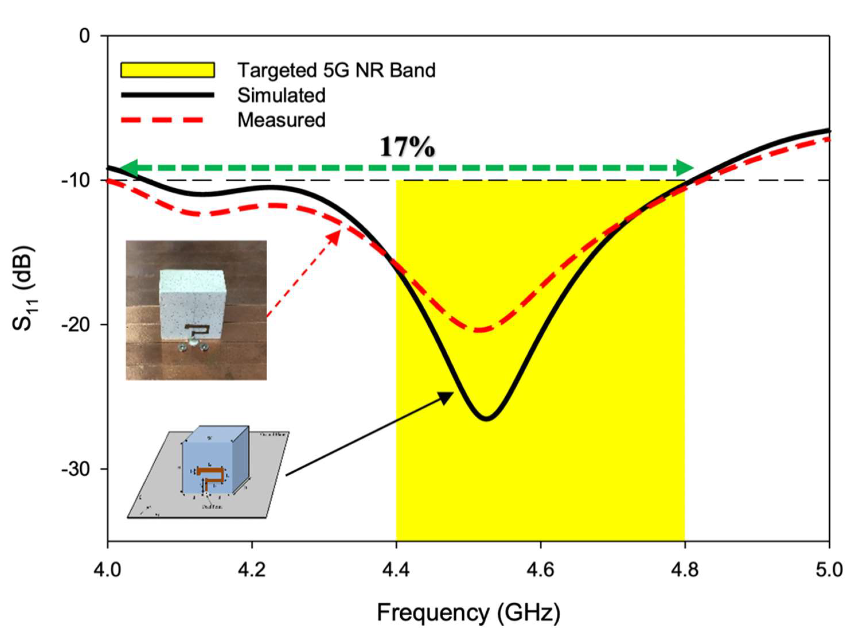
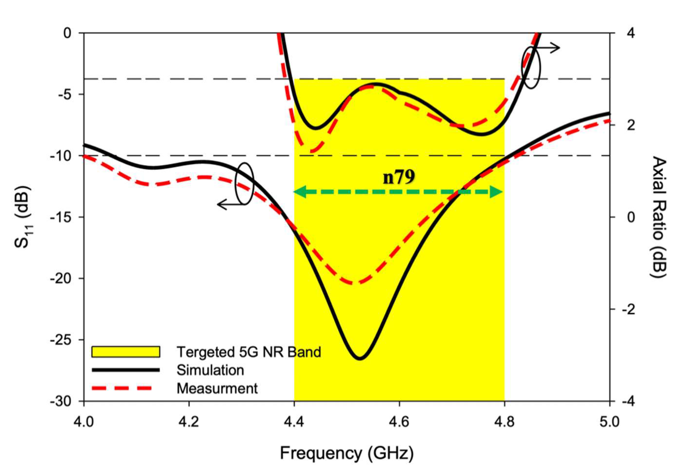
| 5 | 10 | 1.5 | 10 | 17 | 100 | ||
| 9 | 5 | 12 | 2 | 5.07 | 7.9 | 48.3 | |
| 7.5 | 5 | 5 | 8 | 4 | 6.15 | 7.42 | 77.5 |
| 6 | 6 | 3.5 | 4.71 | 7.2 | 100 | ||
| 2.5 | 7.08 | 6.97 | 43.4 | ||||
| 7 | 9 | 2 | 6.15 | 6.75 | 100 | ||
| 2 | 6.1 | 6.54 | 100 | ||||
| 7 | 7 | 8 | 1.5 | 5.3 | 6.34 | 100 | |
| 3.5 | 10.47 | 10.91 | 60.3 | ||||
| 9 | 6 | 10 | 3 | 4.05 | 7.66 | 100 |
| Antenna | Geometry | No of Strips | 10-dB S11 Bandwidth (%) | 3-dB AR Bandwidth (%) | Polarization | 5G NR n79 Coverage (4.4–4.8 GHz) |
|---|---|---|---|---|---|---|
| Geometry 1 |  | 1 | Nil | Nil | Linear | NO |
| Geometry 2 |  | 2 | Nil | Nil | Circular | NO |
| Geometry 3 |  | 3 | Nil | 2 | Circular | NO |
| Geometry 4 |  | 4 | 8.8 | 5.8 | Circular | NO |
| Proposed CP 5G RDRA |  | 5 | 17 | 10 | Circular | YES |
| Excited Mode of 5G CP RDRA | DWM Estimation | CST Calculation | Experimental Measurement |
|---|---|---|---|
| TE | (GHz) | (GHz) | (GHz) |
| 3.89 | 4.13 | 4.12 | |
| 4.53 | 4.52 | 4.51 |
| Ref. | Design Configuration | Excitation Mechanism | Mode of Excitation | Usable CP Frequency | Usable CP Bandwidth | Gain (dBic) | Antenna Geometry | |
|---|---|---|---|---|---|---|---|---|
| [18] | 10 & 3.5 | Rectangular multilayered DRA | Cross-slot with microstrip line | & | 10.5−11.5 GHz | 9.5% | 11 | Complex |
| [19] | 10 | Four metallic walls surrounded RDRA | Cross-slot with microstrip line | 2.2−3.5 GHz | 46.9% | 4.37 | Complex | |
| [20] | 9.6 | Rectangular DRA with two annular vias | Microstrip line coupled rectangular slot | 3.28−3.46 GHz | 5.5% | 6–7.1 | Complex | |
| [21] | 9.8 | Rectangular DRA | Triangular aperture with parasitic strip | 3.46−3.54 GHz | 2.29% | 5 | Complex | |
| [22] | 20.5 | Rectangular DRA | Cross-slot-coupled | 1.25−1.3 GHz | 2.2% | 4.3 | Complex | |
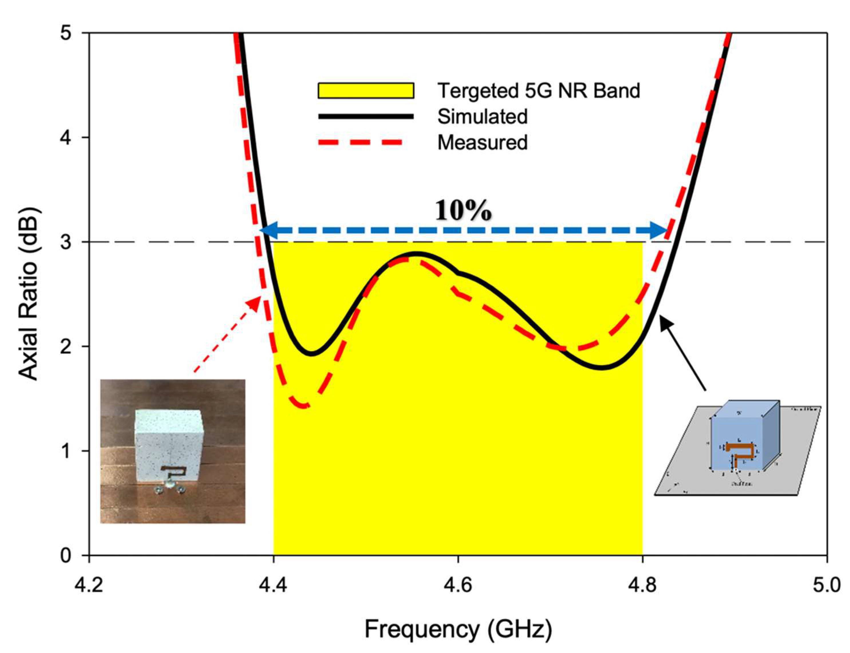
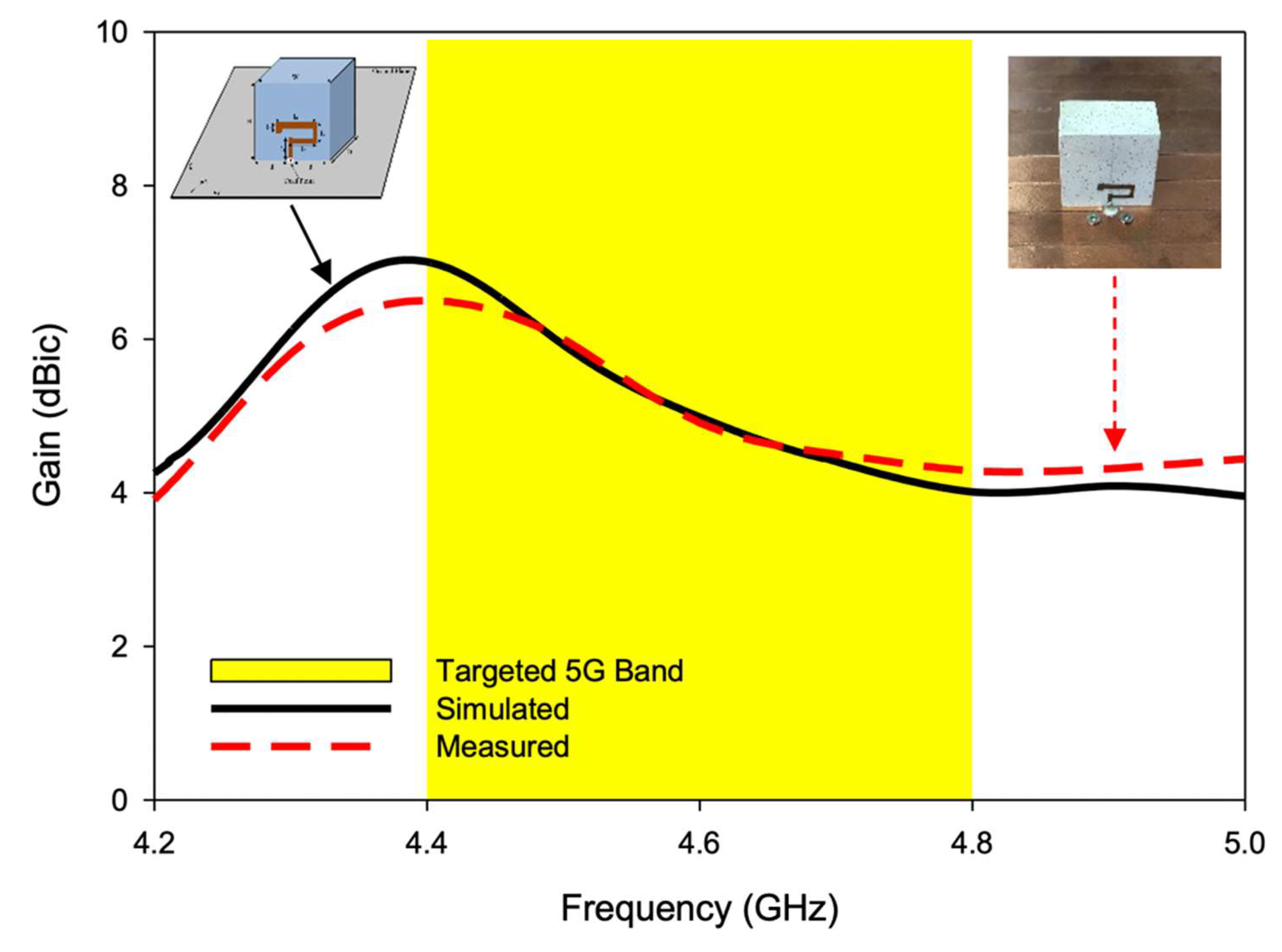
| Proposed CP 5G RDRA | 10 | Rectangular DRA | Unique conformal strip | 4.4−4.8 GHz | 10% | 6.2 | Simple |
Publisher’s Note: MDPI stays neutral with regard to jurisdictional claims in published maps and institutional affiliations. |
© 2022 by the authors. Licensee MDPI, Basel, Switzerland. This article is an open access article distributed under the terms and conditions of the Creative Commons Attribution (CC BY) license (https://creativecommons.org/licenses/by/4.0/).
Share and Cite
Illahi, U.; Iqbal, J.; Irfan, M.; Ismail Sulaiman, M.; Khan, M.A.; Rauf, A.; Bari, I.; Abdullah, M.; Muhammad, F.; Nowakowski, G.; et al. A Novel Design and Development of a Strip-Fed Circularly Polarized Rectangular Dielectric Resonator Antenna for 5G NR Sub-6 GHz Band Applications. Sensors 2022, 22, 5531. https://doi.org/10.3390/s22155531
Illahi U, Iqbal J, Irfan M, Ismail Sulaiman M, Khan MA, Rauf A, Bari I, Abdullah M, Muhammad F, Nowakowski G, et al. A Novel Design and Development of a Strip-Fed Circularly Polarized Rectangular Dielectric Resonator Antenna for 5G NR Sub-6 GHz Band Applications. Sensors. 2022; 22(15):5531. https://doi.org/10.3390/s22155531
Chicago/Turabian StyleIllahi, Usman, Javed Iqbal, Muhammad Irfan, Mohamad Ismail Sulaiman, Muhammad Abbas Khan, Abdul Rauf, Inam Bari, Mujeeb Abdullah, Fazal Muhammad, Grzegorz Nowakowski, and et al. 2022. "A Novel Design and Development of a Strip-Fed Circularly Polarized Rectangular Dielectric Resonator Antenna for 5G NR Sub-6 GHz Band Applications" Sensors 22, no. 15: 5531. https://doi.org/10.3390/s22155531