
Power Electronics for Modern Sustainable Power Systems: Distributed Generation, Microgrids and Smart Grids—A Review


Faculty of Electrical Engineering, Federal University of Uberlandia, Uberlândia 38400-902, Brazil
*
Author to whom correspondence should be addressed.
Sustainability 2022, 14(6), 3597; https://doi.org/10.3390/su14063597
Submission received: 18 February 2022
/
Revised: 10 March 2022
/
Accepted: 14 March 2022
/
Published: 18 March 2022
(This article belongs to the Topic Distributed Generation and Storage in Power Systems)
Abstract
:This work presents and discusses the application of power electronics for the integration of several distributed generation sources, as well as those related to it, the microgrids and the smart grids, to the power sector. Trends and challenges are addressed for the area of study and an embracing overview of the main technologies and techniques is presented for future investigation. As there are many power electronics devices available for employment, in each one of these crucial, modern, sustainable electrical systems, it is important for students, researchers and professionals to understand and compare the state of the art of them all, for the right choice in their respective uses. These apparatuses not only allow grid matching, but also provide new functions that enhance these artifacts’ operations, and of the entire power system. Thus, in this paper, the relationship between power electronics and distributed generation is detailed, with the role and classification of each static converter for the improved operation of wind power, photovoltaic systems, fuel cells, small hydro and microturbines exposed. While the first two are more widely covered in the literature, the last three are rarely discussed and differentiated, in terms of their power electronics interfaces. Then, the same is made for microgrids and smart grids, also scarcely approached in other works, with regard to the characteristics of the power converters applied, confirming their superior performances with the use of power electronics. Finally, conclusions are given.
1. Introduction
Power electronics, the field where semiconductor equipment is studied and developed for the efficient conversion of electrical energy, through advanced control methods, has been playing an increasingly important role in the world. Their devices find applications in the most varied areas of technology, involving electricity. Industrial, mobility and energy sectors raise their productivities and improve the quality of their services when making use of them [1].
At the same time, distributed generation (DG), mainly in the form of renewable energies, has aroused great interest in recent years, due to its admirable potential benefits, such as reduction in the emission of greenhouse gases and pollution in general, improvements in reliability and in power quality, private production of electricity, employment generation, among others [2,3]. Its adoption, and that of its related technologies of microgrids and smart grids, seems the right way to achieve the Sustainable Development Goal (SDG) 7 of the United Nations’ 2030 Agenda, for ensuring “access to affordable, reliable, sustainable and modern energy for all” [4]. It is not by chance that DG has expanded and penetrated all the points of the power system. Indeed, the total installed capacity in the whole world of the most acclaimed sources of DG, solar photovoltaic and wind power, grows exponentially, with the former rising from about 72 GW to 710 GW, and the second from approximately 220 GW to 732 GW, between 2011 and 2020 [5].
Despite this favorable prospect for DG and its affine technologies, problems can arise from its inadequate connections within the power system and its negative impacts can come in several different ways. In the power system’s protection, it can come in the form of non-intended islanding, incorrect automatic reclosing and misleading relay coordination [6,7]. In the power system’s control and stability, changes in the short-circuit level and impacts in the inertia’s constant are some of the possibilities [8]. In the power quality, the injection of current harmonics, the elevation of voltage sags and, in the flicker level, more frequent swells and interruptions, are some examples [9,10,11].
This apparently tragic scenario does not contradict the huge investment that has been made in the DG market. What explains this seemingly paradoxical phenomenon is the fact that, with the correct integration, the number of benefits outweighs the losses, or even eliminates them completely. This is where static power electronic converters come in. These devices can not only make DG compatible with the grid, but can also improve their operation and the overall operation of the system, in terms of efficiency, cost, reliability and power quality. It is also thanks to them that it is possible to erect microgrids and smart grids. For these reasons, it is imperative for today’s power engineers, and all other professionals involved with the energy and sustainability sectors, to understand the relationship between these technologies.
Thus, this work intends to elucidate how the interaction between power electronics, DG, microgrids and smart grids happens. Its purpose is not to detail topologies, but rather to understand the role and importance of power electronics for these three technologies, as well as categorize and differentiate, explicitly, the converters used in each one of them. Moreover, advantages and disadvantages are highlighted.
Other papers found in the literature cover similar topics to the ones addressed here [12,13,14]. Nevertheless, their focuses are mainly on the most popular DG sources: wind turbines and photovoltaic systems. Of course, these are fundamental structures to study, considering their power electronics strategies. Thereby, they are also analyzed in this work, including additional distinct information. However, there are other DG technologies that are rarely mentioned in this scenario: fuel cells, small hydro and microturbines. They are also highly beneficiated from static converters. The last two, for example, are more traditionally known and their conventional similar forms, hydroelectric and thermoelectric power plants, would not greatly profit from power electronics. This is not the case for the new technologies, which work properly only with the direct application of power electronics, as will be explained later. Moreover, although power converters are primordial elements for the operation of microgrids and smart grids, these combined systems and their features are not comprehensively discussed in other general reviews.
In this context, trying to fill a gap found in recent published review articles, concerning Power Electronics for Modern Sustainable Power Systems, the remainder of this article is structured as follows: In Section 2, different configurations, using power converters for integrating some of the DG technologies into the power system, are approached, with wind power, photovoltaic systems, fuel cells, small hydro and microturbines being discussed. In Section 3, microgrids are the main object of study. In Section 4, the theme is smart grids. In both cases, the importance of power electronics is clarified. Finally, conclusions are presented.
2. Power Electronics and Distributed Generation
In this paper, DG is defined as any electric power production technology that can be easily installed in a great variety of geographic and physical locations, regardless of where it is connected (transmission, distribution or consumption side) and of its size, being spread throughout the entire power system or isolated. It, therefore, encompasses wind power, photovoltaic systems, fuel cells, small hydro, cogeneration, biomass energy, small thermal generators and other sources [2].
These technologies, however, have the most distinct electric outputs, while the power system requires current, voltage and frequency standardized parameters. To solve this problem in such a way that none of these devices are disturbed or damaged, there must be means to connect the two. The equipment that accomplishes this task is called “interface”. According to some authors [6,15], and with the IEEE 1547 standard [16], the interfaces can be divided into three basic categories: synchronous machines (SM), induction machines (IM) and power electronics converters. The former two are part of systems that must convert mechanical power to electric power. The output can be, or not, appropriated for the power system. The converters, in turn, are imperative for some sources and can improve the performances of other ones, even if they are already composed of SM or IM. Figure 1 illustrates the connection of DG with the power system through power electronics.
The result of using static converters is that all of the power system’s requirements are attended with high efficiency, but not only that. Other positive characteristics from these DG devices can be provided, such as the provision of ancillary services, active grid management, maximum power extraction, harmonics control, reactive support and voltage regulation [17]. In the next sections, particular DG cases, with the use of power electronics as interface, are explored.
2.1. Power Electronics and Wind Power
Wind power is the technology that transforms the energy from the wind into electricity. This conversion is realized by wind turbines, with the horizontal axis with three blade types being the most used [18]. One of its classifications makes clear the strong bond with power electronics, since the division is given by the degree of dependence with it. Namely, wind turbines can be independent, partially dependent or totally dependent on power electronics converters as interface [12]. Each one of them will be exposed, but it is interesting to notice, beforehand, that even the operation of the independent ones can be enriched with the use of converters. Other classification is based on the speed; if it is or is not variable [13,19]. Relating these two classifications, it can be verified that the independent one does not have variable speed, while the others have.
Wind turbines independent of power electronics (Figure 2a) are coupled directly with the grid, by induction generators with a squirrel-cage rotor. With torque variations, its speed changes minimally (1−2%), which leads to it being considered fixed. Besides that, by the type of the generator used, the turbine requires reactive power absorption. This compensation can be done by the grid or, more usually, locally, by switched capacitor banks (5 to 25 steps) [12]. The biggest advantage of power electronics for this category is in the initial connection of the turbine to the power system. When this occurs, there is a transient with high inrush currents. These currents can have their values substantially reduced with the use of a thyristor converter, the soft starter. After this transient regime, a bypass switch connects the wind turbine directly to the grid [20]. Advantages of the independent turbines that can be considered are the simple construction, the low cost and the absence of complex converters. The disadvantages are the constant speed, the mechanical reinforcements necessary to avoid wear [19] and the possibility of flicker appearance, if the grid is weak, as a consequence of the wind fluctuations [13].
The second classification of turbines, partially dependent, can be partitioned as follows: rotor resistance and doubly fed induction generator (DFIG). Both of them are more complex and expensive solutions. In contrast with the independent ones, however, these have variable speed. In the first one (Figure 2b), this variation is partial, and it differs a little in its structure from those of non-variable speed. The only two modifications are that the rotor is a wounded one and one external variable resistance, controlled by a power electronics converter, is connected to it. This allows for changes in the machine slip, and consequently, although small, in its speed and its output power.
For the DFIG (Figure 2c), the rotor is still the wounded one. However, it is connected, via slip rings, to the power system by a back-to-back converter (AC-DC with a DC-AC) that controls its frequency and, therefore, its speed. The stator is directly coupled to the grid. The first advantage is that, with a small converter (30% of the nominal power of the turbine), a broad variation of speed can be achieved (typically 30% higher or lower than the synchronous speed). The second advantage is the control of the active and reactive powers. In the case of the latter, the compensation is made internally, dispensing the use of capacitor banks. This configuration also makes a smooth connection with the grid, without external means [20]. With these advantages, the wind turbine can participate in ancillary services, besides contributing with improvements in power quality. One last interesting advantage is the reduced noise, due to the low speed with calm winds. On the other hand, one disadvantage is the presence of harmonics of high frequency, which forces the installation of filters in wind parks [19].
The third and last category, the totally dependent wind turbines (Figure 2d), has its electric machines fully connected to the power system with power electronics as the interface (back-to-back). There are various benefits. Beyond the complete speed variation, there is the intern reactive compensation, the smooth connection to the grid [13] and the fast and complete control of active and reactive powers [19]. In contrast, the converter adds losses, complexity and sensibility to the system. The electric machine in this category can be the induction generator of the squirrel-cage rotor type, the conventional synchronous generator (with few poles), the multiple-pole synchronous generator and the permanent magnet (PM) synchronous generator. These last two have the great advantage of eliminating the use of the gearbox. The removal of this item, also present in the other two categories of wind turbines, provides the system with lower maintenance, losses and costs and greater reliability [14]. When synchronous generators, with the exception of the PM, are adopted, the field excitation can be done with the addition of a small rectifier, whose input is the power system itself.
Table 1 summarizes the main characteristics of the different wind turbine classifications, in line with their respective power electronics dependencies.
A 2016 report [21] showed that power electronics, independent and partially dependent with rotor resistance wind turbines, have an almost insignificant relative participation in global market share since 2013. In 2015, for onshore wind parks, the DFIG category was still the favorite one, with an installed capacity of approximately 50% in Europe and around 75% in Asia, North America and the rest of the World. In Europe, however, totally dependent wind turbines also have a nearly 50% market share. In offshore wind parks, this last class is dominant. The different configurations follow a proportional relationship with the wind turbine nominal power. The DFIG concept is the most used for those turbines below 2 MW, while the totally dependent is the preferred solution for capacities higher than that [21]. As there is a strong trend in growing power rating for wind turbines with an average size of 2.6 MW onshore and 5.7 MW offshore machines delivered in 2019, and configurations as large as 12 MW [22], and because of its advantages, such as full power controllability, the totally dependent category will soon be completely predominant in the wind power industry.
2.2. Power Electronics and Photovoltaic Systems
Photovoltaic systems are formed by photovoltaic cells that transform the sunlight directly into electricity. One group of connected cells is called a photovoltaic module or panel, while a photovoltaic array can be considered either a synonym of the latter, or a larger system, formed by several of them connected in series or parallel [23]. The union of panels, in series, also receives a special name: photovoltaic strings. Each one of these schemes provides different voltages, currents and powers. However, for all of them, the output is DC, which makes power electronics mandatory for most parts of the applications.
The apparatuses, which make possible the corresponding electrical link between the photovoltaic arrays and the AC systems, are called indistinctly solar inverters, and may be composed of a single AC-DC stage or by two stages, having one or more DC-DC converters at the front of an inverter itself. Depending on the arrangement between the arrays and the converters and their number, the solar inverters can be classified in five categories, as shown in Figure 3, Figure 4 and Figure 5.
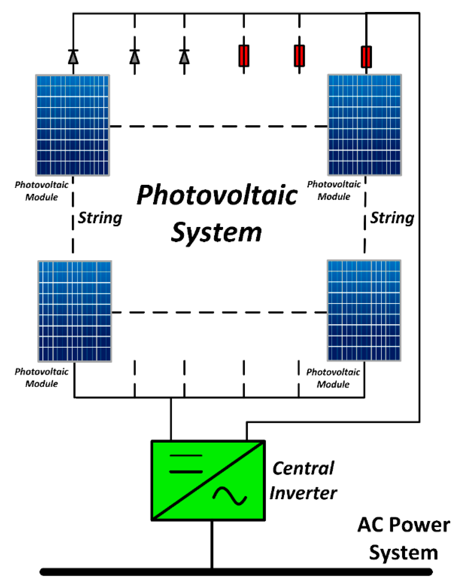
The central inverters (Figure 3) are commonly adopted for systems with relatively high powers and a large number of photovoltaic panels. A single unit can satisfy the entire array. Not infrequently, the strings present in these cases provide voltage high enough to dispense a DC-DC step-up stage or a transformer. On the other hand, diodes or fuses are inserted in each one of them for protection against reverse currents. Some disadvantages are the use of a single maximum power point tracking (MPPT) system, the lack of reliability because of the dependence on only one inverter unit for a big array, the incompatibility between the panels, the losses in the diodes and the use of high voltage DC cables [24].
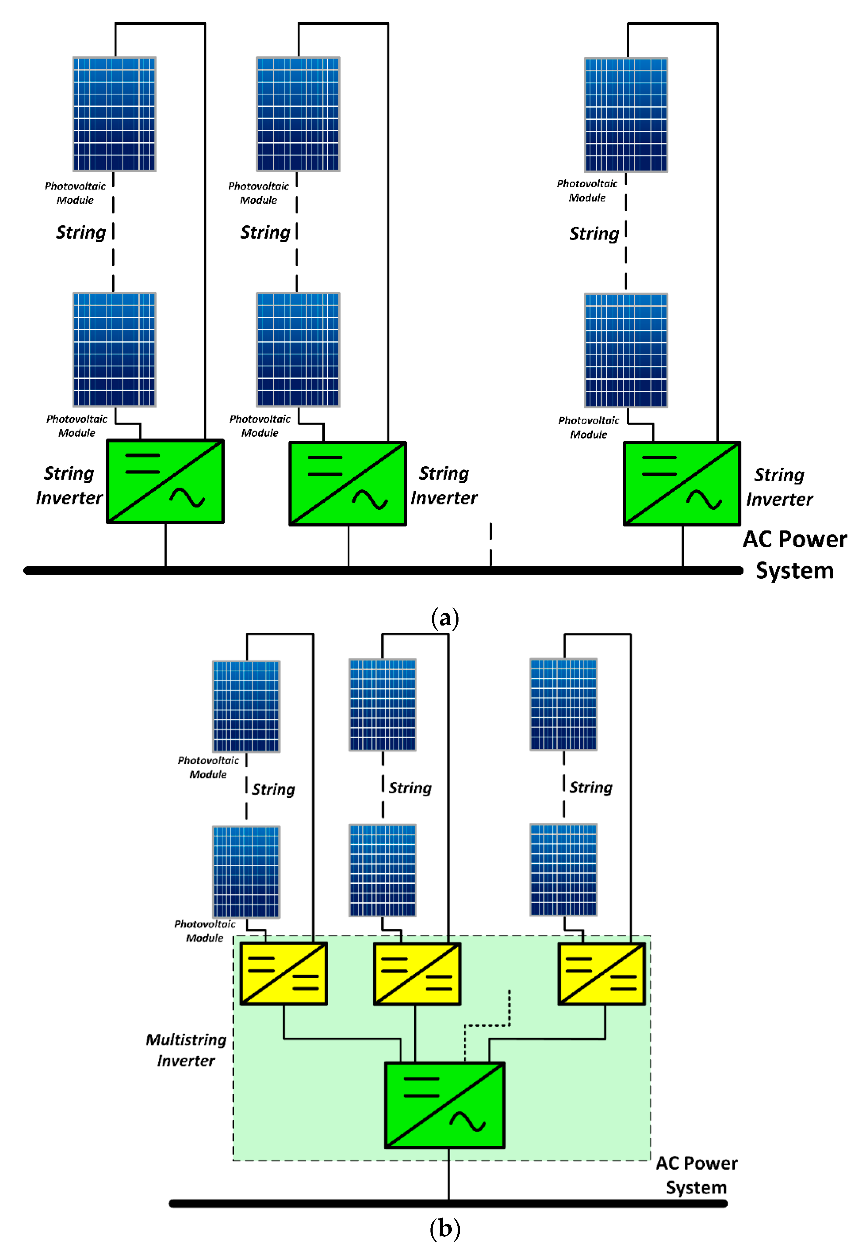
The second configuration is the one of string inverters (Figure 4a) that are, as the name indicates, the ones that are dedicated to each one of the strings. This characteristic allows a higher yield, since the MPPT is oriented and diodes are not used. Again, if the voltage for each string is satisfactory, then there is no need for additional devices to elevate the voltage.
The third category is the one of multistring inverters (Figure 4b). This one is composed of DC-DC converters for each one of the strings and a single DC-AC converter common to all of them. The greatest advantage is the increased efficiency due to the MPPT being individual for each string and having more control. Aside from this, there is an increase in the flexibility because strings from different technologies and orientations can have a unique connection, in addition to the owner being able to later increase the number of panels of its power plant [14].
The fourth of the five configurations is that of the microinverters (Figure 5a). These are connected in one, two, three or four PV(Photovoltaic) modules, having a DC-DC converter, being two-stage or single-stage, with or without a high frequency transformer. The MPPT is panel individual, which augments, considerably, the efficiency and the compatibility. Another interesting characteristic is the fact that the use of microinverters makes the panels plug-and-play devices. In other words, even people with little knowledge of photovoltaic systems can easily install and connect this category. Another consequence is a more flexible arrangement of the panels. In its turn, the high cost of having a single inverter for only one or two panels is a disadvantage [24]. More disadvantages are the narrow MPPT voltage range and the low reliability in the long term, since the system is susceptible to more failures, due to the high temperatures it can reach (more than 60 °C in some cases).
The last configuration of solar inverters is that of the photovoltaic power optimizers (Figure 5b). They are an enhancement of the string inverter, with some benefits of the microinverters. Each one of them is a DC-DC converter that is attached directly to the photovoltaic module, which gives them individual MPPT, yielding a higher efficiency and a wide MPPT voltage range. The photovoltaic power optimizers and the photovoltaic modules are connected in series, forming a string, which, in turn, is connected to a string inverter. The entire system is, therefore, simple, has a high reliability and has fewer components. On the other hand, some of the disadvantages are the high cost, a minimal string length and an improved security system, due to the risk of arcing on the DC wires between the photovoltaic modules and the string inverter [25]. Table 2 summarizes some of the attributes of the solar inverter categories presented.
A factor that is important to highlight is the presence, or not, of transformers in the inverters’ topologies. The use of them, no matter the type, brings galvanic isolation. However, both types, the high frequency transformer of DC-DC converters and the one with low frequency, connected to the grid, diminishes the efficiency of the system. The second one also impairs the inverters by expanding the space occupied, increasing weight, elevating its costs and making the installation more difficult. Proposing to remedy these problems, the more used option has been the transformerless inverters, where the transformer is absent [26,27].
The challenges of adopting this solution begin by the complexity of the topologies. The structures are based, primarily, on the groups of the Full-bridge and Neutral Point Clamped (NPC) single-phase inverters. In the first case, the classical H-bridge, with bipolar, unipolar or hybrid modulation is a trend, as well as the others, more developed, such as the H5, the HERIC, that with DC bypass and the zero-voltage rectifier. For the second type, the classical NPC and the Conergy NPC are available. What explains the large range of strategies is the search for transformerless inverters that are more efficient, secure, smaller and less expensive [27]. Each one of them tries to get, for example, higher efficiency, with the achievement of a zero-voltage stage, avoiding reactive power exchange between the grid and the DC side capacitor, a decrease in or the elimination of the high-frequency content and the reduction in the filters’ requirement [28].
For this transformerless inverters family, great attention must be given to the parasitic capacitors and their leakage currents. The structure of the panels, formed by semiconductors, glass and aluminum, linked to the lack of galvanic isolation, brings up a capacitance and possible currents that can bring risks to people and animals. The calculated value of this capacitance is around 50 and 150 Nf/Kw and depends on various factors, including humidity, distance between the panel and the surface of installation, the material of the cells, among others [29]. The importance of this leakage current is so great that it is determinant in the choice of the transformerless topology [26,27].
One important component of the photovoltaic systems that can be addressed is the MPPT. Perturb and Observe (P&O), Hill Climbing and Incremental Conductance are the more known [30,31], and will be explained here. Nevertheless, there are several others proposed, including more complex methods that use artificial intelligence techniques, such as fuzzy logic and neural networks [32,33]. Recently, even more advanced techniques were proposed and developed, including the musical chairs algorithm (MCA) [34], optimal fuzzy control [35] and nested particle swarm optimization (PSO) [36] methods. The MPPT methods make the photovoltaic arrays work by producing the maximum power available, as changes in irradiation, temperature and in their respective loads, modify their performances. This is reflected in changes in their I-V and P-V operation characteristic curves. The relevance of power electronics is, again, justified here. It is thanks to the DC-DC converters, working with a microcontroller or a digital signal processor (DSP), that the MPPT methods are easily applied. The P&O, as well as the Hill Climbing, operate by disturbing the duty cycle of the DC-DC converter, providing variations (voltage variations for the former and power variations for the latter) that change the point of operation, where the system is working in the P-V curve until it reaches its maximum. The algorithm of the incremental conductance is based on the analysis of the incremental (I/V) and the instantaneous (ΔI/ΔV) conductances. The comparison between the two indicates, with respect to the position of the current point of operation, the position of the maximum power point. Fixed increments of voltage by the DC-DC converter make this point to be reached.
As, specifically, for DC-DC converters, their main functions for photovoltaic applications are voltage regulation and MPPT control, they can be divided in the isolated and non-isolated categories. In the first classification, the buck and boost converters, despite being the cheapest ones, are not well suited because of their weak characteristics in tracking the maximum power point (MPP). The Buck-Boost, Cúk and SEPIC converters have good performance in MPPT, with optimal outcomes. The formal is used in low-power systems, while the last two are better choices for medium-power solutions. In the case of the isolated converters, the flyback-based converters show good results, with high efficiency. In high-power systems, however, H-bridge schemes are superior, mainly in cascaded and multilevel structures. It is important to highlight that the application of any MPPT technique is independent of the topology chosen [37].
2.3. Power Electronics and Fuel Cells
Fuel cells convert chemical energy into electric energy without moving parts and with high efficiency. Pure hydrogen, the main fuel of these devices, does not exist in nature abundantly, but there are many renewable and sustainable sources, such as biomass and solar energy, and methods, including biological processes and plasma reformation, that can be used to produce it [38]. The residues are, generally, only water and heat, with virtually zero greenhouse gases emissions. Besides that, they have high energy density, being up to ten times that of batteries [39]. It is a promising technology with many applications [40], but it still comes at a high price. Power electronics have two roles to make them viable: allow proper operation and reduce costs.
The output of these devices is DC and, therefore, the interface is similar to the one used in photovoltaic systems, the conversion from DC to AC being mandatory for the most part of the applications. The theoretical maximum voltage that each cell produces is 1.2 V [39]. Just like the photovoltaic cells, the fuel cells can be connected together in series and in parallel, to obtain higher levels of voltage and current. With lower power ratings, an inverter stage may be sufficient. In this situation, the number of components is small, the switching losses and frequency variations are lower, and the efficiency is higher. However, since DC voltage in low-power fuel cell systems (less than 1 Kw) is low and applications require higher voltages, a high-gain DC-DC stage is a good solution. On the other hand, when the power rating is superior, this additional stage is largely employed to avoid the use of low-frequency transformers, which are expensive, bulky and heavy. A high-frequency transformer is appropriate in this case due to the lower cost [41]. In addition, the DC-DC converter is very important because it performs the DC isolation function for fuel cell systems [12] and controls the voltage profile, since the fuel cells have some restrictions, such as lower performance with more ripple current, problems with currents in reverse direction and slow response to load changes [42]. It also allows integrated power factor correction and enables proper operation as uninterruptible power supply (UPS) systems [43]. The application of a high-frequency inverter, followed by an AC-AC converter, is also an option [12]. These main structures are illustrated in Figure 6.
2.4. Power Electronics and Small Hydro
Hydroelectric power plants are one of the oldest forms of electricity production, existing for more than a century. Over time, their technology has had little meaningful change, with the exception of the size and the power ratings. Recently, however, they have undergone positive changes due to power electronics. Previously, static converters only attended for rotor excitation and for high-voltage direct current (HVDC) transmission, but not as interface. With its advances and the expansion of small hydro, this picture has changed.
Conventional SM was, for a long time, the most used technology for hydroelectric plants. With the advent of modern small hydro, other types of generators have been chosen, as well as power electronics have gained more room for this DG technology. One of the reasons for this is that the flow variations have more impact on them than the traditional large-scale hydroelectric power stations. A significant benefit of these is the reservoir type, where water is stored by large natural or artificial dams and can be released for the controlled production of electricity. The small hydro power plants, in turn, are often of the run-of-river types, where accumulation is minimal or zero [44]. They depend, therefore, fundamentally, on the natural velocity of the waters and of the flows available at the moment.
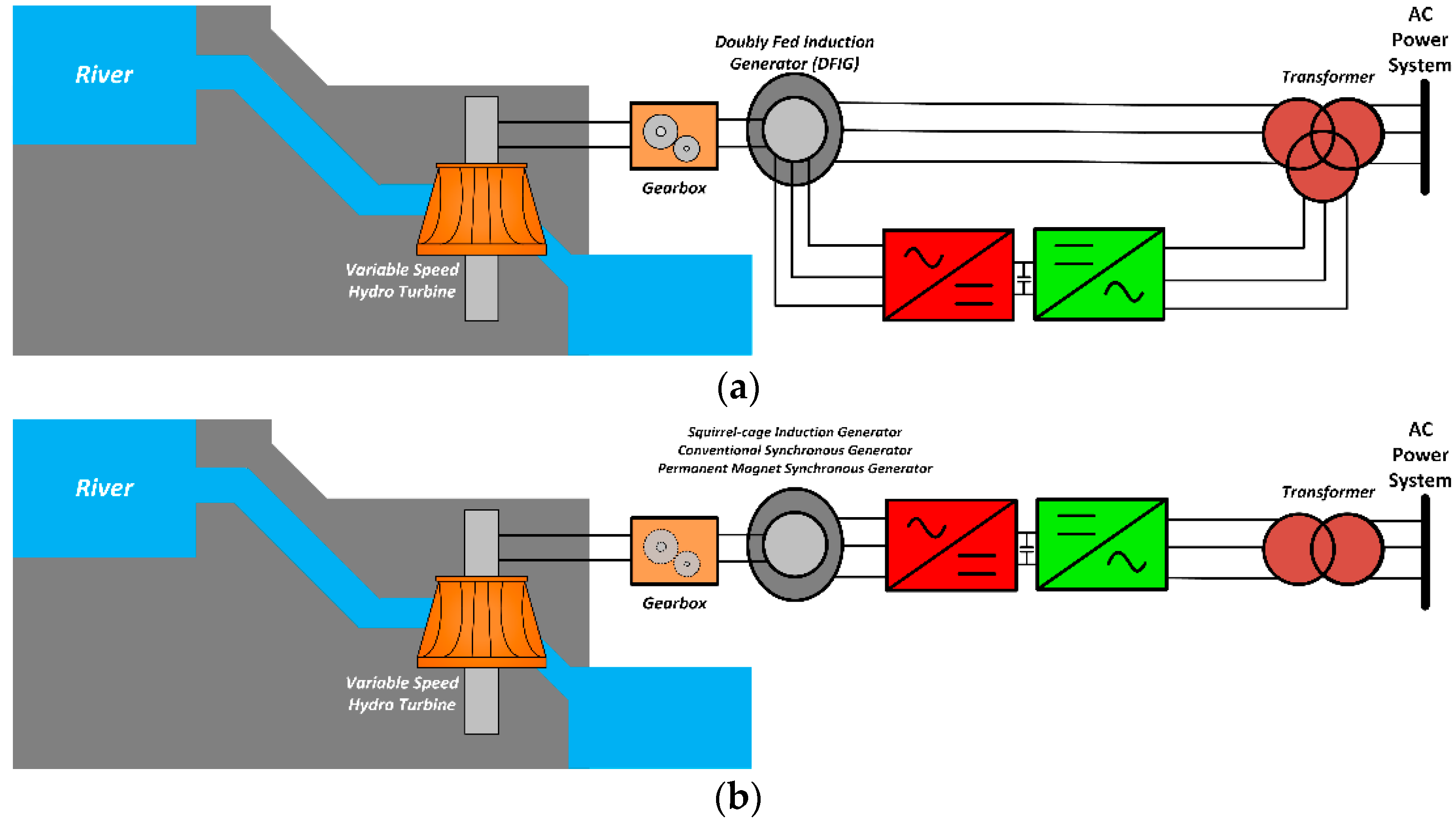
Such specifications require devices that provide more appropriate solutions. The PM SM and the IM are preferred to solve these impasses. The first ones are coupled with fixed speed turbines and gearboxes, and they directly connect the system to the grid [45]. Using the fixed speed solution, variations in the water flow will provoke instability. In this way, variable speed solutions have enhanced operations for small hydro. The benefits are, beyond stability, higher efficiency, flexibility and even smaller flooded areas. In the mechanical part, the variable speed turbine, Francis, is pointed out as the best performance for small hydro. In electrical terms, the power electronics converters have a great importance. The two most common systems adopted are similar to those used in wind turbines. In one of them, the DFIG model, adapted for small hydro, configures a partially dependent power electronics system. In the other one, a totally dependent system, a back-to-back (AC-DC and DC-AC) converter, interweaves the power system with the generator, which can be the squirrel-cage IM, the conventional synchronous and the PM one [45,46]. Figure 7 shows these systems, with variable speed hydro turbines, and their respective electric machines and power electronics schemes.
2.5. Power Electronics and Microturbines
Microturbines are a modern, small-scale electric power generation system technology. They can use several renewable sources, such as biomass [47], biodiesel fuel [48], waste-derived fuels [49], and can compound a combined heat-and-power (CHP) system [50,51]. They work similarly to the traditional turbines, producing electricity from burning some fuel, producing steam, which, in turn, is used to rotate an electrical machine. However, microturbines are smaller and more compact, since they are coupled to the generator in a single-shaft structure, eliminating the gearbox. The speed is, therefore, very high, reaching from 50,000 RPM to 120,000 RPM. For these reasons, a PM SM is the commonly chosen generator [52].
The output is AC, with high frequency, and the connection with the grid cannot be done directly, the use of a power electronics converter being an obligation for this task. To reach the grid frequency (60 or 50 Hz), a three-phase thyristor [52] or diode [53] rectifier can be connected to the output of the electric machine, followed by a voltage source inverter linked to the grid. Figure 8 exhibits this type of microturbine structure. More recently, however, the Pulse Width Modulation (PWM) rectifier has been a favorable choice, due to the reduction in the harmonic components produced that can elevate losses and augment the temperature of the generator [54].
3. Power Electronics and Microgrids
Microgrids can be defined as locally controlled clusters of DG technologies, energy storage and loads, forming a single system that can work in parallel with a grid, as well as in intentional islanding [55,56]. In the parallel operation, microgrids have given external voltage and frequency references, most of the time, by the distribution system, which they are connected to. The islanding operation consists of the opposite of the parallel operation, working in isolation from the rest of the power system, without external voltage or frequency references [57]. Having their own local electric power production and being independent from the grid, microgrids bring greater reliability to their participants and higher power quality. Aside from this, microgrids reunite all the DG benefits in technical, economic, social and environmental terms.
The whole operation of microgrids relies, fundamentally, on their control systems. These are all implemented through the converters connected to the DG units or other devices. To control them is to control the microgrid. Thus, power electronics are essential here. The control strategies are generally divided into two categories: centralized and distributed [58]. In the first case, a central controller defines how each power converter will work in the microgrid, determining its entire performance. In the latter, each converter measures, calculates and decides locally its behavior, without communication with the other units, which are, nevertheless, working in parallel with it.
In an AC microgrid, the power converters may be classified by their control functions in the microgrid [59,60]. Grid-forming converters are those that establish the voltage amplitude and frequency of the microgrid, working as an ideal voltage source (Figure 9a). Grid-feeding converters follow the voltage and frequency references from other units to inject power to the microgrid. It is analogous to an ideal current source (Figure 9b). The last of the converters is the grid-supporting configuration, in which voltage and frequency outputs are regulated to assist the operation of the microgrid (Figure 9c). In Figure 9, Z is an equivalent impedance, i0 is a reference current, and v0 is a reference voltage.
In order for microgrids to have an enhanced performance with control, reliability and flexibility, the DG technologies must have two characteristics: plug-and-play and peer-to-peer [61]. This means that, in the first place, the DG insertion into the microgrid must be independent of any changes in the control and protection of the whole system. They must be simply connected and used as the name indicates, without affecting the other components of the microgrid. In the second place, the system must also be independent of essential devices that provide the parameters for the operation of the rest of the elements of the microgrid. In other words, in the absence of any DG, the microgrid should not completely interrupt its operation. These two attributes can be easily achieved with the use of power electronics. To realize the correct operation of AC microgrids and endow them with the two aforementioned characteristics, a hierarchical control system, with four levels, is proposed [59,62]. The zero level comprehends the intern voltage and current loops of the converters.
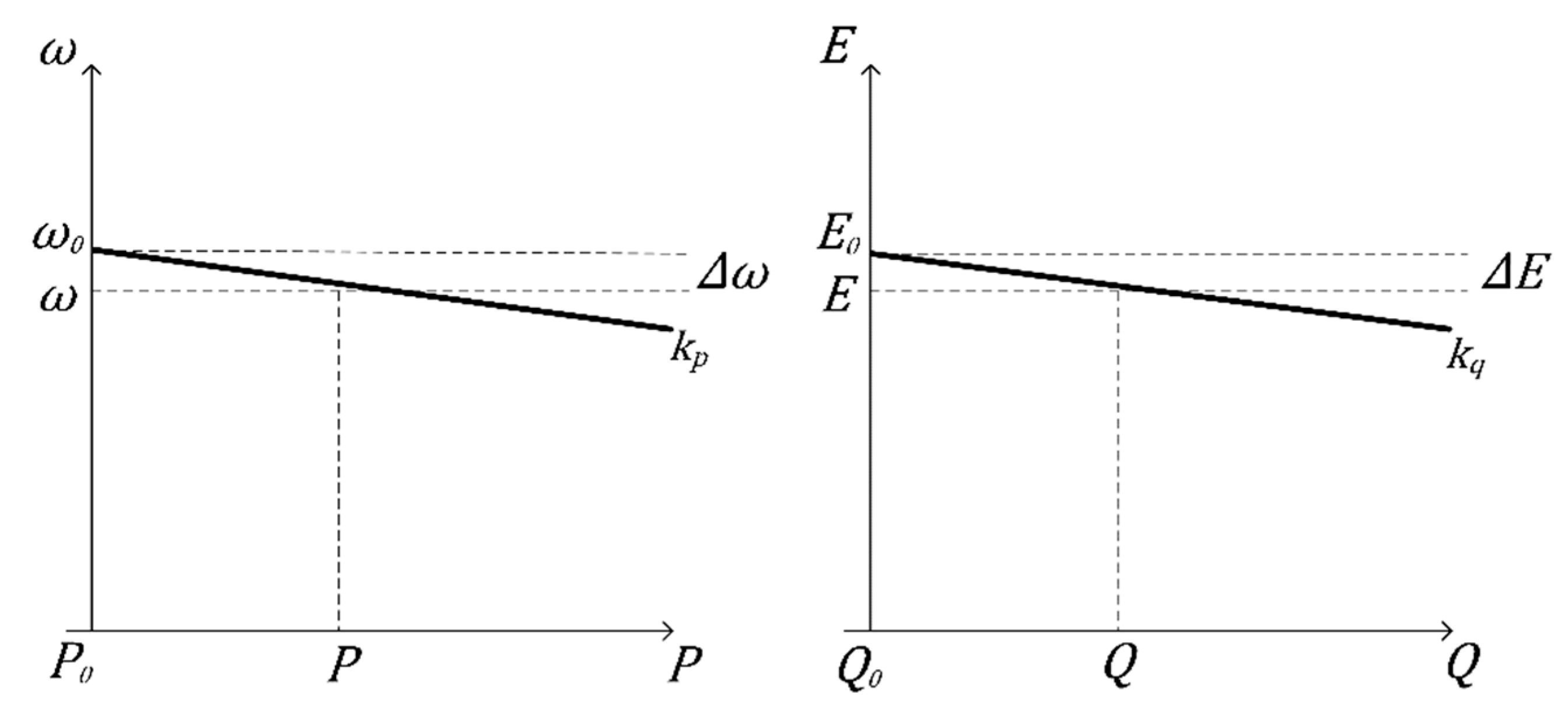
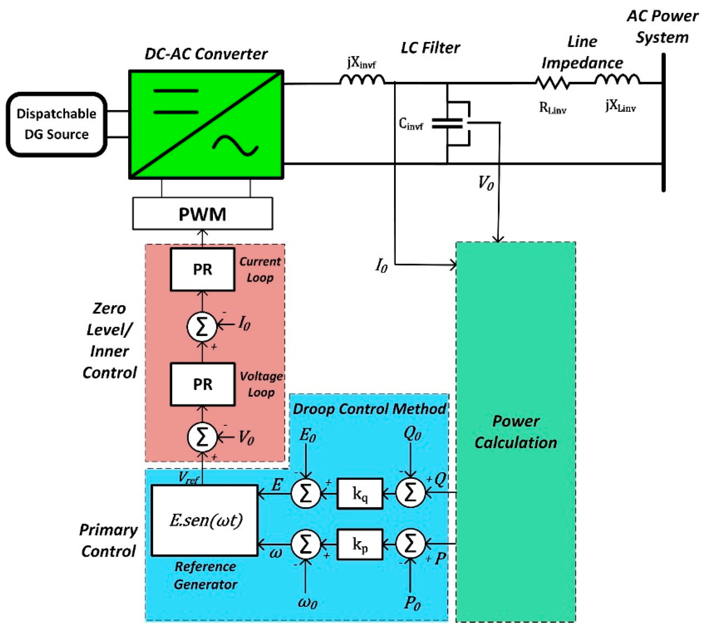
The primary control commands the islanding operation of the microgrid. Although different techniques have been proven to be applied and have great results, such as the master–slave, the droop control method has been the most adopted one, since it provides the electric power sharing of the converters, in parallel with great reliability, without the use of communication systems and with only local measurements [63]. Moreover, such a choice enables the fulfillment of the plug-and-play and peer-to-peer characteristics. In the droop control method, the inverters mimic the multiple SM in parallel behavior in isolated systems. This means that, implementing this technique in the control system of each one of the inverters, in parallel, it is possible to regulate frequency and voltage through the power control. These characteristic relationships between the active power and frequency (P-ω) and the reactive power and voltage (Q-V) are represented in Figure 10, and are given by Equations (1) and (2). The complete control diagram of the inverter, with internal and primary controls, can be seen in Figure 11 (PR: Proportional-Resonant controller).
where ω and E are, respectively, the output frequency and voltage, ω0 and E0 are also frequency and voltage, but the reference ones, kP and kQ are the frequency and voltage droop constants, and P and Q are the active and reactive powers, and P0 and Q0, are the reference active and reactive powers.
Such relationships are valid only if the grid, to which the inverters are connected, is predominantly inductive. The microgrids are, however, generally connected to the distribution system, which has characteristics just opposite to this (X/R < 1). To work around this problem, and still obtain precise power sharing, a virtual impedance loop is added to the inverter control, which emulates the inductive behavior with the grid frequency [64].
The secondary control is for restoration and synchronization. If the microgrid is in islanding operation, under the primary control regime, the voltage and frequency magnitudes of the inverters may not be in the power system baselines. When connecting or reconnecting to the grid, the secondary control uses an external controller and communication, to compensate the deviations in all the converters with power system parameters being measured and used as references. At the end of the procedure, when all of them are established in nominal values of the grid, a bypass switch that intermediates the microgrid with the power system is closed to connect or reconnect both [59].
Lastly, the tertiary control allows the bidirectional active and reactive power flow control between the microgrid and the power system. This is obtained with the comparison between the local powers and reference powers, with the respective action of the microgrid converters [62]. This control involves not only technical, but also economic aspects. In fact, the correct control of the converters enables the microgrids to offer ancillary services, such as voltage and frequency regulation, black-start, as well as improvements in the power quality, such as harmonic compensation, flicker reduction, among others [59].
The hierarchical control of DC microgrids is similar to that of the AC microgrids, having the same control levels [62]. They are, however, simpler. The zero level is still associated with the voltage and current intern loops. The primary control, in turn, is linked to the emulation of virtual resistance, analogous to the AC virtual impedance, which must avoid the current circulation between the sources in parallel, if there is a voltage difference between them. The secondary control has the function of restoration, correcting the voltage deviation, while the tertiary control operates with power flow control, between the DC microgrid and the system in which it is connected.
As can be seen, power electronics are a basilar element in the operation of microgrids. In fact, they are more than that. One of the great benefits of using static converters for deploying microgrids is that they make their architectures extremely diverse. Since power electronics will allow microgrids to work with different devices, such as the many distinct DG technologies and storage systems available in the market, and will adapt their electric outputs as required, there is an infinite number of ways to design their structures. A microgrid can be formed by different production devices, but it can work in the same voltage and frequency levels at any point of it, even if they have incompatible natures, such as wind, solar and microturbines. There are AC, DC and hybrid (AC and DC), single-phase and three-phase microgrids [65,66]. They can be radial or meshed. Their sizes and capacities vary greatly. They can be installed in many different geographic locations. All this is mainly because of the use of power electronics.
One last note about microgrids and power electronics is the connection to the power grid. Traditionally, to physically connect electrical systems, mechanical circuit breakers are used. However, microgrids must act very quickly when entering grid-connected mode or changing to islanded mode, so that failures or elevated transients do not occur. The solution is to employ intelligent static transfer switches [67]. These are very fast switches, with an extremely low time of response, making the transitions imperceptible for DG units and loads of the microgrid. They have many other attributes, such as safer, lighter and smaller structures and no movable parts, and can be based on SCR or IGBT electronic switches.
4. Power Electronics and Smart Grids
Smart grids are a new arrangement of the traditional grid, combining and integrating innovative techniques and technologies of the power sector. It is hard to define them, because they encompass a great diversity of characteristics. Beyond incorporating a great amount of communication, automation, information technologies and digitalization in the conventional electrical grid, they also embrace the DG devices that need power electronics for a good operation, as was seen in Section 2, changing the production side of the power system. Another relevant point is that the smart grids are intended to move intelligence to a decentralized state. That means that the many elements that are connected to the grid must have the capacity to solve problems automatically, locally, and with communication among them [68]. In this way, the consumption, the distribution and the transmission sides will also be affected and transformed. These possibilities, as has been indicated in this paper, are inherent to the application of power electronics.
In the generation area of a smart grid, power converters will have to make units act differently from the conventional manner. They must ensure that DG and storage systems will not only inject active power, but will need to export reactive power, give power and voltage support and make decisions, based on real-time measurements and prices [69]. As for some of the DG sources, static converters should handle these with variable and intermittent natures, such as wind and solar, by smoothing their electric outputs. In this sense, for power electronics to be a genuine enabling technology for the deployment of smart grids, they must have some attributes, such as: high efficiency and reliability, synchronization competences, smart metering, self-healing and bidirectional power flow control [70].
In fact, this last characteristic is very relevant in smart grids. There is the possibility of reverse power flow, an uncommon aspect in the traditional electrical system, which reveals power electronics as a fundamental piece in the management and control of the smart grids [71]. Since there are many distinct players, producing and consuming energy in a smart grid, new responsibilities will arise to guarantee the whole security. Power production must be controlled and DG units may need to work in islanded mode. Loads will need to be regulated and reduce their use to contribute to stability. Roles may even change between these components [72]. These features can be reached via power converters. The unification of specific control techniques and power electronics will allow for the creation of intelligent interfaces among these different agents, sometimes called prosumers, organizing and supervising the operation of the smart grids [70].
That is why it is also important to highlight that a link between smart grids and power electronics is the transformation of the distribution system from passive to active [73]. In future power systems, the insertion of different devices, such as DG sources, energy storage systems and controllable loads [74], can bring more problems than solutions, if the fit-and-forget methodology is applied, making conventional investments inevitable. The active management of the grid allows, on the contrary, the full capacity of work from the new and old devices of the grid to be enabled, lowering the costs. One example that makes this clear is reactive power management. If it is permitted that inverters can operate out of the unity power factor condition, and that this parameter is totally controlled, it is possible that utilities will no longer install capacitor banks, avoiding additional costs. Nevertheless, they can obtain a high capacity of electric power transport and better voltage regulation. Moreover, the distinct DG technologies must work together in the distribution system in hybrid structures. The active management through power converters is fundamental here, optimizing the available energy resources [75]. Another example is the participation in ancillary services. If DG could work with this arrangement through its static converters, not just focusing on active power production, it would really be able to replace the problematic large hydroelectric, nuclear and fossil fuel power plants.
To some authors, smart grids are formed by the integration of many smart microgrids, interconnected with communication, data and power exchange [76], working with efficient energy management systems [77]. Thus, it is evident from what was discussed in the last section, the preponderant influence of power converters in smart grids. Moreover, this cluster of smart microgrids can adhere to the hierarchical control by only changing its scale. In this sense, the tertiary control of each one of the microgrids would be the primary control of the group of smart microgrids, and so forth [62].
The high penetration of power electronics in the generation, distribution and consumption areas of the smart grids brings many benefits. Nevertheless, attention should be paid to one particular issue: harmonic production. Converters can inject currents with non-sinuisodal waveforms, and this can cause problems for the power system. Some of the new devices integrated to the smart grids go further than the conventional situations, by introducing non-characteristic harmonics. This must be considered when connecting any technology associated with power electronics in future electrical systems [78].
Finally, on the transmission side, power converters contribute to the emergence of new equipment and practices that aggregate more intelligence, efficiency, control and reliability into their infrastructures. To be able to maintain stability, with more significant power transfer and higher power quality, and considering conventionally atypical properties, such as the bidirectional power flow, flexible transmission systems, such as high-voltage DC (HVDC) and flexible AC transmissions systems (FACTS), devices entirely based on power electronics can be applied [72]. The smart substation is another example of the direct implementation of power electronics. Automatization and self-healing are some of the attributes attained in this way. One last example is the power line communication (PLC), where a conductor in the transmission system is used, not solely to transport power, but data too. The role of power electronics, here, is to manipulate the waveforms, to send signals and information [79].
5. Conclusions
This paper demonstrated how and why power electronics enormously benefit and enhance the performance of the most modern and sustainable technologies of power production and distribution. Its purpose was to present the research trends that link DG, microgrids and smart grids to static converters, so that those who are interested in such studies can have, to hand, the initial concepts to develop their own projects, acting as a guide for later works. A broad perspective about power converters applied to modern sustainable power systems was given, as well as important insights, showing and explaining the most advanced state-of-the-art technologies and techniques used in each one.
For the DG, the converters not only adapt the electric parameters to coincide with those available in the grid, they also substantially improve the operation of each one of the sources. Higher efficiency, power quality and reliability, advanced control, optimal production and cost reductions are some advantages. Wind turbines tend to be more reliant in power electronics due to the advantages that they bring, eliminating costly equipment that needs maintenance and repair more often, such as the gearbox and the capacitor banks, in addition to providing speed variations and control of the active and reactive powers. For photovoltaic systems, as well as for fuel cells, the static converters are mandatory for AC applications. In the first case, it was seen that the operation is enhanced when power electronics are distributed for a group of panels (strings), or even for each unit, improving the photovoltaic array’s performance through exclusive MPPT, making the most out of the available sunlight. Moreover, the arrays are more flexible and easier to assemble. For the fuel cells, the system can agglomerate different functions, such as integrated power factor correction and the forming of UPS systems. For small hydro, power electronics change from being a simple aid to being fundamental in its operation, especially when they are installed in places where the hydraulic flows are highly variable. Finally, the different small-sized thermic sources, such as CHP and biomass, use microturbines that, in turn, will only work for the most common electrical applications if they have power electronics converters as the interface, since they need to have their high output frequencies adapted.
For microgrids, it was seen that power electronics are essential in order for them to work, providing different control functions and hierarchical control levels that allow parallel to the grid and islanding operation modes, beyond power flow control with the grid. The many distinct and adaptive architectures of microgrids can only be implemented because they use power converters extensively. For smart grids, power electronics are a key piece, in several points on every side of it, from consumption to production, passing through transmission. Among those highlighted in this paper are: intelligent insertion in an embracing way to the power system, DG operation improvement, bidirectional power flow and agent-based controls, the integrated formation of smart microgrids, the transformation of the distribution system, from passive to active, and new devices and techniques for a more advanced and flexible transmission system.
Despite the recent advances, there is a lot to be learned in the relationships among DG, microgrids, smart grids and power electronics. However, as was shown, static converters are becoming protagonists in future grid development. It is up to the professionals in the area to understand and avail the several benefits that they can provide. Thus, in order for the power system to not lose the high power quality and reliability that it has acquired in recent years, and to integrate new technologies that meet the human needs, assist in environment preservation and conservation and mitigate climate change, the adoption of power electronics seems the best answer.
Author Contributions
M.E.T.S.J. and L.C.G.F. conceived, planned, provided critical feedback, improved the final design, analyzed the data, and wrote the paper. All authors have read and agreed to the published version of the manuscript.
Funding
This research was partially financed by the National Council for Scientific and Technological Development (CNPq), under Process 141192/2021-6), the Coordination for the Improvement of Higher Education Personnel (CAPES) and the Research Support Foundation of the State of Minas Gerais (FAPEMIG), under Process TEC-PPM-00485-17.
Institutional Review Board Statement
Not applicable.
Informed Consent Statement
Not applicable.
Data Availability Statement
Not applicable.
Acknowledgments
The authors would like to thank the National Council for Scientific and Technological Development (CNPQ), the Coordination for the Improvement of Higher Education Personnel (CAPES), Research Support Foundation of the State of Minas Gerais (FAPEMIG), and Federal University of Uberlandia (UFU) for supporting and funding this work. They would also like to thank Luiz Carlos de Freitas, João Batista Vieira Júnior, Gustavo Brito de Lima and Ernane Antônio Alves Coelho for supporting this work.
Conflicts of Interest
The authors declare no conflict of interest.
References
- Bose, B.K. Energy, environment, and advances in power electronics. IEEE Trans. Power Electron. 2000, 15, 688–701. [Google Scholar] [CrossRef]
- Souza, M.E.T., Jr. Reflexões Acerca da Geração Distribuída e Suas Implicações no Sistema Elétrico, na Sociedade e no Meio Ambiente (Reflexions about Distributed Generation and Its Implications on the Power System, the Society and the Environment); Federal University of Uberlândia: Uberlândia, Brazil, 2018. [Google Scholar]
- Ellabban, O.; Abu-Rub, H.; Blaabjerg, F. Renewable energy resources: Current status, future prospects and their enabling technology. Renew. Sustain. Energy Rev. 2014, 39, 748–764. [Google Scholar] [CrossRef]
- United Nations (UN). Transforming Our World: The 2030 Agenda for Sustainable Development. 2015. Available online: https://sdgs.un.org/2030agenda (accessed on 17 February 2022).
- International Renewable Energy Agency (IRENA). Renewable Capacity Statistics 2021. 2021. Available online: https://www.irena.org/publications/2021/March/Renewable-Capacity-Statistics-2021 (accessed on 17 February 2022).
- Mozina, C.J. The impact of distributed generation. PAC World 2008, 5, 18–25. [Google Scholar]
- Dugan, R.C.; Mcdermott, T.E. Distributed generation. IEEE Ind. Appl. Mag. 2002, 8, 19–25. [Google Scholar] [CrossRef]
- Knyazkin, V.; Ackermann, T. Interaction between distributed generation and the distribution network: Operation aspects. In Proceedings of the 17th International Conference on Electricity Distribution (CIRED), Yokohama, Japan, 6–10 October 2003. [Google Scholar]
- Barker, P.P.; De Mello, R.W. Determining the impact of distributed generation on power systems. I. Radial distribution systems. In Proceedings of the 2000 Power Engineering Society Summer Meeting, Seattle, WA, USA, 16–20 July 2000; Volume 3, pp. 1645–1656. [Google Scholar]
- Bollen, M.H.J.; Yang, Y.; Hassan, F. Integration of distributed generation in the power system—A power quality approach. In Proceedings of the 13th International Conference on Harmonics and Quality of Power, Wollongong, Australia, 28 September–1 October 2008; pp. 1–8. [Google Scholar]
- Dugan, R.C.; McGranaghan, M.F.; Santosa, S.; Beaty, H.W. Electrical Power Systems Quality, 2nd ed.; McGraw-Hill: New York, NY, USA, 2003. [Google Scholar]
- Blaabjerg, F.; Chen, Z.; Kjaer, S.B. Power electronics as efficient interface in dispersed power generation systems. IEEE Trans. Power Electron. 2004, 19, 1184–1194. [Google Scholar] [CrossRef]
- Blaabjerg, F.; Iov, F.; Kerekes, T.; Teodorescu, R.; Ma, K. Power electronics—key technology for renewable energy systems. In Proceedings of the 2nd Power Electronics, Drive Systems and Technologies Conference, Tehran, Iran, 16–17 February 2011; pp. 445–466. [Google Scholar]
- Carrasco, J.M.; Franquelo, L.G.; Bialasiewicz, J.T.; Galván, E.; PortilloGuisado, R.C.; Prats, M.M.; Leon, J.I.; Moreno-Alfonso, N. Power-electronic systems for the grid integration of renewable energy sources: A survey. IEEE Trans. Ind. Electron. 2006, 53, 1002–1016. [Google Scholar] [CrossRef]
- Bollen, M.H.J.; Hassan, F. Integration of Distributed Generation in the Power System; John Wiley & Sons, Inc.: Hoboken, NJ, USA, 2011. [Google Scholar]
- IEEE Std 1547-2018 (Revision of IEEE Std 1547-2003); IEEE Standard for Interconnection and Interoperability of Distributed Energy Resources with Associated Electric Power Systems Interfaces. IEEE: Piscataway Township, NJ, USA, 2018.
- Kroposki, B.; Pink, C.; DeBlasio, R.; Thomas, H.; Simões, M.; Sen, P.K. Benefits of power electronic interfaces for distributed energy systems. IEEE Trans. Energy Convers. 2010, 25, 901–908. [Google Scholar] [CrossRef] [Green Version]
- Islam, M.R.; Mekhilef, S.; Saidur, R. Progress and recent trends of wind energy technology. Renew. Sustain. Energy Rev. 2013, 21, 456–468. [Google Scholar] [CrossRef]
- Chen, Z.; Guerrero, J.M.; Blaabjerg, F. A review of the state of the art of power electronics for wind turbines. IEEE Trans. Power Electron. 2009, 24, 1859–1875. [Google Scholar] [CrossRef]
- Blaabjerg, F.; Liserre, M.; Ma, K. Power electronics converters for wind turbine systems. IEEE Trans. Ind. Appl. 2011, 48, 708–719. [Google Scholar] [CrossRef] [Green Version]
- European Commission; Joint Research Centre (JRC); Villalba Pradas, A.; Telsnig, T.; Vázquez Hernández, C. JRC Wind Energy Status Report: Market, Technology and Regulatory Aspects of Wind Energy: 2016 Edition. 2018. Available online: https://op.europa.eu/en/publication-detail/-/publication/d131d668-0a13-11e7-8a35-01aa75ed71a1/language-en (accessed on 4 March 2022).
- REN21. Renewables 2020 Global Status Report. 2020. Available online: https://www.ren21.net/reports/global-status-report/ (accessed on 4 March 2022).
- Villalva, M.G.; Gazoli, J.R.; Ruppert Filho, E. Comprehensive approach to modeling and simulation of photovoltaic arrays. IEEE Trans. Power Electron. 2009, 24, 1198–1208. [Google Scholar] [CrossRef]
- Kjaer, S.B.; Pedersen, J.K.; Blaabjerg, F. A review of single-phase grid-connected inverters for photovoltaic modules. IEEE Trans. Ind. Appl. 2005, 41, 1292–1306. [Google Scholar] [CrossRef]
- Vinnikov, D.; Chub, A.; Liivik, E.; Kosenko, R.; Korkh, O. Solar optiverter—A novel hybrid approach to the photovoltaic module level power electronics. IEEE Trans. Ind. Electron. 2018, 66, 3869–3880. [Google Scholar] [CrossRef]
- Kerekes, T.; Teodorescu, R.; Borup, U. Transformerless Photovoltaic Inverters Connected to the Grid. In Proceedings of the APEC 07—Twenty-Second Annual IEEE Applied Power Electronics Conference and Exposition, Anaheim, CA, USA, 25 February–1 March 2007; pp. 1733–1737. [Google Scholar]
- Melo, F.C.; Garcia, L.S.; de Freitas, L.C.; Coelho, E.A.; Farias, V.J.; de Freitas, L.C. Proposal of a photovoltaic AC-module with a single-stage transformerless grid-connected boost microinverter. IEEE Trans. Ind. Electron. 2017, 65, 2289–2301. [Google Scholar] [CrossRef]
- Teodorescu, R.; Liserre, M.; Rodriguez, P. Grid Converters for Photovoltaic and Wind Power Systems; John Wiley & Sons: Hoboken, NJ, USA, 2011. [Google Scholar]
- Chen, W.; Yang, X.; Zhang, W.; Song, X. Leakage current calculation for PV inverter system based on a parasitic capacitor model. IEEE Trans. Power Electron. 2016, 31, 8205–8217. [Google Scholar] [CrossRef]
- Ishaque, K.; Salam, Z. A review of maximum power point tracking techniques of PV system for uniform insolation and partial shading condition. Renew. Sustain. Energy Rev. 2013, 19, 475–488. [Google Scholar] [CrossRef]
- Esram, T.; Chapman, P.L. Comparison of photovoltaic array maximum power point tracking techniques. IEEE Trans. Energy Convers. 2007, 22, 439–449. [Google Scholar] [CrossRef] [Green Version]
- Eltawil, M.A.; Zhao, Z. MPPT techniques for photovoltaic applications. Renew. Sustain. Energy Rev. 2013, 25, 793–813. [Google Scholar] [CrossRef]
- Reisi, A.R.; Moradi, M.H.; Jamasb, S. Classification and comparison of maximum power point tracking techniques for photovoltaic system: A review. Renew. Sustain. Energy Rev. 2013, 19, 433–443. [Google Scholar] [CrossRef]
- Eltamaly, A.M. A novel musical chairs algorithm applied for MPPT of PV systems. Renew. Sustain. Energy Rev. 2021, 146, 111135. [Google Scholar] [CrossRef]
- Kim, J.-C.; Huh, J.-H.; Ko, J.-S. Optimization design and test bed of fuzzy control rule base for PV system MPPT in micro grid. Sustainability 2020, 12, 3763. [Google Scholar] [CrossRef]
- Eltamaly, A.M. A novel strategy for optimal PSO control parameters determination for PV energy systems. Sustainability 2021, 13, 1008. [Google Scholar] [CrossRef]
- Raghavendra, K.V.G.; Zeb, K.; Muthusamy, A.; Krishna, T.N.V.; Kumar, S.V.S.; Kim, D.H.; Kim, M.; Cho, H.; Kim, H.J. A comprehensive review of DC–DC converter topologies and modulation strategies with recent advances in solar photovoltaic systems. Electronics 2020, 9, 31. [Google Scholar] [CrossRef] [Green Version]
- Chaubey, R.; Sahu, S.; James, O.O.; Maity, S. A review on development of industrial processes and emerging techniques for production of hydrogen from renewable and sustainable sources. Renew. Sustain. Energy Rev. 2013, 23, 443–462. [Google Scholar] [CrossRef]
- Cheng, K.W.E.; Sutanto, D.; Ho, Y.L.; Law, K.K. Exploring the power conditioning system for fuel cell. In Proceedings of the 2001 IEEE 32nd Annual Power Electronics Specialists Conference, Vancouver, BC, Canada, 17–21 June 2001; Volume 4, pp. 2197–2202. [Google Scholar]
- Sharaf, O.Z.; Orhan, M.F. An overview of fuel cell technology: Fundamentals and applications. Renew. Sustain. Energy Rev. 2014, 32, 810–853. [Google Scholar] [CrossRef]
- Kirubakaran, A.; Jain, S.; Nema, R.K. A review on fuel cell technologies and power electronic interface. Renew. Sustain. Energy Rev. 2009, 13, 2430–2440. [Google Scholar] [CrossRef]
- Das, V.; Padmanaban, S.; Venkitusamy, K.; Selvamuthukumaran, R.; Blaabjerg, F.; Siano, P. Recent advances and challenges of fuel cell based power system architectures and control–A review. Renew. Sustain. Energy Rev. 2017, 73, 10–18. [Google Scholar] [CrossRef]
- Maciel, R.S.; de Freitas, L.C.; Coelho, E.A.A.; Vieira, J.B.; de Freitas, L.C.G. Front-end converter with integrated PFC and DC–DC functions for a fuel cell UPS with DSP-based control. IEEE Trans. Power Electron. 2014, 30, 4175–4188. [Google Scholar] [CrossRef]
- Paish, O. Small hydro power: Technology and current status. Renew. Sustain. Energy Rev. 2002, 6, 537–556. [Google Scholar] [CrossRef]
- Nababan, S.; Muljadi, E.; Blaabjerg, F. An overview of power topologies for micro-hydro turbines. In Proceedings of the 2012 3rd IEEE International Symposium on Power Electronics for Distributed Generation Systems (PEDG), Aalborg, Denmark, 25–28 June 2012; pp. 737–744. [Google Scholar]
- Singh, R.R.; Chelliah, T.R.; Agarwal, P. Power electronics in hydro electric energy systems–A review. Renew. Sustain. Energy Rev. 2014, 32, 944–959. [Google Scholar] [CrossRef]
- Jurado, F.; Cano, A.; Carpio, J. Biomass based micro-turbine plant and distribution network stability. Energy Convers. Manag. 2004, 45, 2713–2727. [Google Scholar] [CrossRef]
- Nascimento, M.A.; Lora, E.S.; Corrêa, P.S.; Andrade, R.V.; Rendon, M.A.; Venturini, O.J.; Ramirez, G.A. Biodiesel fuel in diesel micro-turbine engines: Modelling and experimental evaluation. Energy 2008, 33, 233–240. [Google Scholar] [CrossRef]
- Seljak, T.; Katrašnik, T. Designing the microturbine engine for waste-derived fuels. Waste Manag. 2016, 47, 299–310. [Google Scholar] [CrossRef] [PubMed]
- Dong, L.; Liu, H.; Riffat, S. Development of small-scale and micro-scale biomass-fuelled CHP systems–A literature review. Appl. Therm. Eng. 2009, 29, 2119–2126. [Google Scholar] [CrossRef] [Green Version]
- Karellas, S.; Karl, J.; Kakaras, E. An innovative biomass gasification process and its coupling with microturbine and fuel cell systems. Energy 2008, 33, 284–291. [Google Scholar] [CrossRef]
- Bertani, A.; Bossi, C.; Fornari, F.; Massucco, S.; Spelta, S.; Tivegna, F. A microturbine generation system for grid connected and islanding operation. In Proceedings of the IEEE PES Power Systems Conference and Exposition, New York, NY, USA, 10–13 October 2004; Volume 1, pp. 360–365. [Google Scholar]
- Lasseter, R.H. Dynamic models for micro-turbines and fuel cells. In Proceedings of the 2001 Power Engineering Society Summer Meeting. Conference Proceedings, Vancouver, BC, Canada, 15–19 July 2001; Volume 2, pp. 761–766. [Google Scholar]
- Khaburi, D.A.; Nazempour, A. Design and simulation of a PWM rectifier connected to a PM generator of micro turbine unit. Sci. Iran. 2012, 19, 820–828. [Google Scholar] [CrossRef] [Green Version]
- Lasseter, R.H. MicroGrids. In Proceedings of the 2002 IEEE Power Engineering Society Winter Meeting. Conference Proceedings, New York, NY, USA, 27–31 January 2002; Volume 1, pp. 305–308. [Google Scholar]
- Hatziargyriou, N.; Asano, H.; Iravani, R.; Marnay, C. Microgrids. IEEE Power Energy Mag. 2007, 5, 78–94. [Google Scholar] [CrossRef]
- Villeneuve, P.L. Concerns generated by islanding. IEEE Power Energy Mag. 2004, 2, 49–53. [Google Scholar] [CrossRef]
- Olivares, D.E.; Mehrizi-Sani, A.; Etemadi, A.H.; Cañizares, C.A.; Iravani, R.; Kazerani, M.; Hajimiragha, A.H.; Gomis-Bellmunt, O.; Saeedifard, M.; Palma-Behnke, R.; et al. Trends in microgrid control. IEEE Trans. Smart Grid 2014, 5, 1905–1919. [Google Scholar] [CrossRef]
- Rocabert, J.; Luna, A.; Blaabjerg, F.; Rodriguez, P. Control of power converters in AC microgrids. IEEE Trans. Power Electron. 2012, 27, 4734–4749. [Google Scholar] [CrossRef]
- Katiraei, F.; Iravani, R.; Hatziargyriou, N.; Dimas, A. Microgrids management. IEEE Power Energy Mag. 2008, 6, 54–65. [Google Scholar] [CrossRef]
- Lasseter, R.H.; Paigi, P. Microgrid: A conceptual solution. In Proceedings of the 2004 IEEE 35th Annual Power Electronics Specialists Conference, Aachen, Germany, 20–25 June 2004; Volume 6, pp. 4285–4290. [Google Scholar]
- Guerrero, J.M.; Vasquez, J.C.; Matas, J.; De Vicuña, L.G.; Castilla, M. Hierarchical control of droop-controlled AC and DC microgrids—A general approach toward standardization. IEEE Trans. Ind. Electron. 2010, 58, 158–172. [Google Scholar] [CrossRef]
- Coelho, E.A.A.; Cortizo, P.C.; Garcia, P.F.D. Small-signal stability for parallel-connected inverters in stand-alone AC supply systems. IEEE Trans. Ind. Appl. 2002, 38, 533–542. [Google Scholar] [CrossRef]
- Guerrero, J.M.; De Vicuna, L.G.; Matas, J.; Castilla, M.; Miret, J. Output impedance design of parallel-connected UPS inverters with wireless load-sharing control. IEEE Trans. Ind. Electron. 2005, 52, 1126–1135. [Google Scholar] [CrossRef]
- Guerrero, J.M.; Chandorkar, M.; Lee, T.L.; Loh, P.C. Advanced control architectures for intelligent microgrids—Part I: Decentralized and hierarchical control. IEEE Trans. Ind. Electron. 2012, 60, 1254–1262. [Google Scholar] [CrossRef] [Green Version]
- Guerrero, J.M.; Loh, P.C.; Lee, T.L.; Chandorkar, M. Advanced control architectures for intelligent microgrids—Part II: Power quality, energy storage, and AC/DC microgrids. IEEE Trans. Ind. Electron. 2012, 60, 1263–1270. [Google Scholar] [CrossRef] [Green Version]
- Kroposki, B.; Pink, C.; Lynch, J.; John, V.; Daniel, S.M.; Benedict, E.; Vihinen, I. Development of a high-speed static switch for distributed energy and microgrid applications. In Proceedings of the 2007 IEEE Power Conversion Conference, Nagoya, Japan, 2–5 April 2007; pp. 1418–1423. [Google Scholar]
- Amin, S.M.; Wollenberg, B.F. Toward a smart grid: Power delivery for the 21st century. IEEE Power Energy Mag. 2005, 3, 34–41. [Google Scholar] [CrossRef]
- Carnieletto, R.; Brandao, D.I.; Farret, F.A.; Simões, M.G.; Suryanarayanan, S. Smart grid initiative. IEEE Ind. Appl. Mag. 2011, 17, 27–35. [Google Scholar] [CrossRef]
- Simões, M.G.; Roche, R.; Kyriakides, E.; Suryanarayanan, S.; Blunier, B.; McBee, K.D.; Nguyen, P.H.; Ribeiro, P.F.; Miraoui, A. A comparison of smart grid technologies and progresses in Europe and the US. IEEE Trans. Ind. Appl. 2012, 48, 1154–1162. [Google Scholar] [CrossRef] [Green Version]
- Momoh, J.A. Smart Grid: Fundamentals of Design and Analysis; John Wiley & Sons, Inc.: Hoboken, NJ, USA, 2012. [Google Scholar]
- Liserre, M.; Sauter, T.; Hung, J.Y. Future energy systems: Integrating renewable energy sources into the smart power grid through industrial electronics. IEEE Ind. Electron. Mag. 2010, 4, 18–37. [Google Scholar] [CrossRef]
- Djapic, P.; Ramsay, C.; Pudjianto, D.; Strbac, G.; Mutale, J.; Jenkins, N.; Allan, R. Taking an active approach. IEEE Power Energy Mag. 2007, 5, 68–77. [Google Scholar] [CrossRef]
- Albogamy, F.R.; Khan, S.A.; Hafeez, G.; Murawwat, S.; Khan, S.; Haider, S.I.; Basit, A.; Thoben, K.-D. Real-Time Energy Management and Load Scheduling with Renewable Energy Integration in Smart Grid. Sustainability 2022, 14, 1792. [Google Scholar] [CrossRef]
- Aziz, A.S.; Tajuddin, M.F.N.; Adzman, M.R.; Ramli, M.A.M.; Mekhilef, S. Energy Management and Optimization of a PV/Diesel/Battery Hybrid Energy System Using a Combined Dispatch Strategy. Sustainability 2019, 11, 683. [Google Scholar] [CrossRef] [Green Version]
- Farhangi, H. The path of the smart grid. IEEE Power Energy Mag. 2009, 8, 18–28. [Google Scholar] [CrossRef]
- Ramli, M.A.M.; Bouchekara, H.R.E.H.; Alghamdi, A.S. Efficient Energy Management in a Microgrid with Intermittent Renewable Energy and Storage Sources. Sustainability 2019, 11, 3839. [Google Scholar] [CrossRef] [Green Version]
- Bollen, M.H.; Etherden, N.; Yang, K.; Chang, G.W. Continuity of supply and voltage quality in the electricity network of the future. In Proceedings of the 2012 IEEE 15th International Conference on Harmonics and Quality of Power, Hong Kong, China, 17–20 June 2012; pp. 375–377. [Google Scholar]
- Fang, X.; Misra, S.; Xue, G.; Yang, D. Smart grid—The new and improved power grid: A survey. IEEE Commun. Surv. Tutor. 2011, 14, 944–980. [Google Scholar] [CrossRef]
Figure 1.
Main DG interface configurations with power converters. Alternating current (AC) and direct current (DC).
Figure 1.
Main DG interface configurations with power converters. Alternating current (AC) and direct current (DC).

Figure 2.
Wind turbine configurations: (a) independent, (b) partially dependent with rotor resistance, (c) partially dependent DFIG and (d) totally dependent of power electronics.
Figure 2.
Wind turbine configurations: (a) independent, (b) partially dependent with rotor resistance, (c) partially dependent DFIG and (d) totally dependent of power electronics.

Figure 3.
Solar central inverter configuration.

Figure 4.
Solar inverter configurations: (a) string inverter and (b) multistring inverter.

Figure 5.
Solar inverter configurations: (a) microinverter and (b) photovoltaic power with power optimizer.
Figure 5.
Solar inverter configurations: (a) microinverter and (b) photovoltaic power with power optimizer.

Figure 6.
Main configurations of two-stage power converters for fuel cells.

Figure 7.
Variable speed small hydro categories: (a) partially dependent DFIG and (b) totally dependent of power electronics.
Figure 7.
Variable speed small hydro categories: (a) partially dependent DFIG and (b) totally dependent of power electronics.

Figure 8.
Microturbine structure with a rectifier followed by an inverter.

Figure 9.
Control functions of AC microgrid converters: (a) grid forming, (b) grid feeding and (c) grid supporting [59].
Figure 9.
Control functions of AC microgrid converters: (a) grid forming, (b) grid feeding and (c) grid supporting [59].

Figure 10.
Frequency and voltage droop characteristics.

Figure 11.
Inner and primary controls diagram (droop control method) of a DG unit and inverter for AC microgrid.
Figure 11.
Inner and primary controls diagram (droop control method) of a DG unit and inverter for AC microgrid.


Table 1.
Discussion about the main advantages and disadvantages of wind turbine configurations.
| Wind Turbine Configuration | Speed Variation | Reactive Compensation | Initial Connection | Electric Machine * | Gearbox | Comments |
|---|---|---|---|---|---|---|
| Independent | Fixed; Minimum (1−2%) | Grid; Capacitor banks | High inrush; Soft-starter | Squirrel-cage IG | Apply | Simple construction; Low cost; Possibility of flicker |
| Partially dependent with rotor resistance | Variable; Partial (small) | Grid; Capacitor banks | High inrush; Soft-starter | Wounded Rotor IG | Apply | - |
| Partially dependent DFIG * | Variable; Partial (±30%) | Internal | Soft connection; Without external means | DFIG | Apply | Small converter; Active and reactive power control; Reduced noise; Harmonic distortion |
| Totally dependent | Variable; Complete | Internal | Soft connection; Without external means | Squirrel-cage IG; Conventional SG; Multiple-pole SG; PM SG | Apply; Except: Multiple-pole and PM SG | Complete, fast active and reactive power control; High cost; Complex and sensible |
* DFIG: doubly fed induction generator; IG: induction generator; SG: synchronous generator; PM: permanent magnet.
Table 2.
Discussion about the main solar inverters’ operational characteristics.
| Solar Inverter Categories | PV System Capacity | PV Modules Connection | MPPT | Diode/Fuse Requirement | Number of Stages | Comments |
|---|---|---|---|---|---|---|
| Central Inverter | High power level | Array Level (all strings) | Array Level (all strings) | Yes | 1 (DC-AC) | High voltage; Panels’ incompatibility (maintenance issue). |
| String Inverter | Low power level | Single string | String Level | No | 1 (DC-AC), 2 (DC-DC + DC-AC) | Good efficiency; Low cost. |
| Multistring Inverter | Low to medium power level | Multiple strings | String Level | Yes * | 2 (DC-DC + DC-AC) | Flexibility; High efficiency. |
| Microinverter | Low power level | Module Level | Module Level | No | 1 (DC-AC) | Plug-and-play device High flexibility/modular; High cost; Excellent for shading conditions. |
| PV Power Optimizer | Low to medium power level | Module Level | Module Level | No | 1 (DC-DC) | High efficiency; Improved security system mandatory; Excellent for shading conditions; Operation together with DC-AC converter. |
* For three or more parallel strings at the MPPT input.
Publisher’s Note: MDPI stays neutral with regard to jurisdictional claims in published maps and institutional affiliations. |
© 2022 by the authors. Licensee MDPI, Basel, Switzerland. This article is an open access article distributed under the terms and conditions of the Creative Commons Attribution (CC BY) license (https://creativecommons.org/licenses/by/4.0/).
Share and Cite
MDPI and ACS Style
Souza Junior, M.E.T.; Freitas, L.C.G. Power Electronics for Modern Sustainable Power Systems: Distributed Generation, Microgrids and Smart Grids—A Review. Sustainability 2022, 14, 3597. https://doi.org/10.3390/su14063597
AMA Style
Souza Junior MET, Freitas LCG. Power Electronics for Modern Sustainable Power Systems: Distributed Generation, Microgrids and Smart Grids—A Review. Sustainability. 2022; 14(6):3597. https://doi.org/10.3390/su14063597
Chicago/Turabian StyleSouza Junior, Marcus Evandro Teixeira, and Luiz Carlos Gomes Freitas. 2022. "Power Electronics for Modern Sustainable Power Systems: Distributed Generation, Microgrids and Smart Grids—A Review" Sustainability 14, no. 6: 3597. https://doi.org/10.3390/su14063597
Note that from the first issue of 2016, this journal uses article numbers instead of page numbers. See further details here.