Article

Optimal PI-Controller-Based Hybrid Energy Storage System in DC Microgrid

by
Maya Vijayan
1,
Ramanjaneya Reddy Udumula
1,*,
Tarkeshwar Mahto
1,
Bhamidi Lokeshgupta
1,
B Srikanth Goud
2,
Ch Naga Sai Kalyan
3,
Praveen Kumar Balachandran
4,
Dhanamjayulu C
5,
Sanjeevikumar Padmanaban
6 and
Bhekisipho Twala
7,*
1
Electrical and Electronics Engineering, SRM University-AP, Neerukonda 522502, India
2
Electrical and Electronics Engineering, Anurag University, Hyderabad 500088, India
3
Electrical and Electronics Engineering, Vasireddy Venkatadri Institute of Technology, Guntur 522508, India
4
Electrical and Electronics Engineering, Vardhaman College of Engineering, Hyderabad 501218, India
5
School of Electrical Engineering, Vellore Institute of Technology, Vellore 632014, India
6
Department of Energy Engineering, Aalborg University, 9100 Aalborg, Denmark
7
Faculty of Engineering and Built Environment, Tshwane University of Technology (BTA), Pretoria 0001, South Africa
*
Authors to whom correspondence should be addressed.
Sustainability 2022, 14(22), 14666; https://doi.org/10.3390/su142214666
Submission received: 5 October 2022 / Revised: 3 November 2022 / Accepted: 4 November 2022 / Published: 8 November 2022
(This article belongs to the Section Energy Sustainability)

Abstract

:
Power availability from renewable energy sources (RES) is unpredictable, and must be managed effectively for better utilization. The role that a hybrid energy storage system (HESS) plays is vital in this context. Renewable energy sources along with hybrid energy storage systems can provide better power management in a DC microgrid environment. In this paper, the optimal PI-controller-based hybrid energy storage system for a DC microgrid is proposed for the effective utilization of renewable power. In this model, the proposed optimal PI controller is developed using the particle swarm optimization (PSO) approach. A 72 W DC microgrid system is considered in order to validate the effectiveness of the proposed optimal PI controller. The proposed model is implemented using the MATLAB/SIMULINK platform. To show the effectiveness of the proposed model, the results are validated with a conventional PI-controller-based hybrid energy storage system.

1. Introduction

Nowadays, DC microgrids are increasingly popular because of their various applications such as electric vehicles (EVs) [1], uninterruptible power supplies (UPS) [2], and so on. DC microgrids consist of various renewable energy sources (RES) such as solar, wind, fuel cells, etc., along with hybrid energy storage systems (HESS) to maximize efficiency and neutralize fluctuating voltage [3]. Generally, the energy storage system (ESS) can be established by various devices such as the battery, supercapacitors (SC), flywheels, ultracapacitors, and so on. Among all storage devices, batteries are the most commonly used for ESSs. The utilization of batteries alone in the ESS can lead to a reduction in battery life due to a longer response time of the battery under rapidly varying environments [4,5]. Thus, the usage of more than one device to form a HESS is becoming popular and has several advantages. The combination of a fast-responding SC along with a slow-responding battery in HESS can reduce the burden on the battery from the intermittent nature of an RES. Here, the SC has a higher power capacity to meet power fluctuations during the transient period, and similarly, the battery has a high energy capacity to compensate for power requirements during a steady state [6,7]. The structure of the DC microgrid is illustrated in Figure 1, and connects various power generation systems, RESs, ESSs, and different types of loads such as EVs, smart buildings, etc. The necessity of sustainable energy has motivated researchers to focus upon study of the DC microgrid.
In a HESS, the steady-state period is handled by the battery, while in the transient period the SC regulates the power flow [8,9,10,11,12,13,14,15]. A HESS with a better energy-management scheme will improve the life of the battery and reduce issues related to the DC microgrid [7]. To understand the better energy operation of a HESS, a detailed comparison of batteries with supercapacitors [16] is shown in the Table 1.
Bidirectional converters play a vital role in the better power management of DC microgrid environments. The various converter configurations, such as isolated and non-isolated topologies, are presented in the literature for integrating a HESS with a DC microgrid. Non-isolated topologies are mostly preferred over isolated topologies, due to their ease of control. Bidirectional DC-DC boost converter topologies are more accurate for HESS applications [1]. Dual active bridge converters [17], interleaved bidirectional converters [18], and bidirectional SEPIC converters [19] are also finding application in HESSs. Non-isolated buck-boost converters are employed between the source and load to provide bidirectional operation. Figure 2 shows the different HESS configurations presented in the literature. Figure 2a,b shows a passive HESS configuration, where the battery and SC are directly connected to the DC bus. The major limitation of this configuration is that it is uncontrollable. Figure 2c,d represents a semi-active configuration, where one of the storage devices is connected to a converter and the other is directly connected to the DC bus. Figure 2e,f shows an active configuration, which consists of a converter for both the ESSs. Therefore, this configuration is fully controllable and more efficient. In an active configuration, either two DC-DC converters can be separately connected to the ESS, as in Figure 2e, or a multiple-input DC-DC converter topology can be used, as depicted in Figure 2f.
There are numerous control algorithms reported in the literature, such as artificial intelligence, fuzzy controls, artificial neural networks, game theory, and genetic algorithms [20,21,22,23,24]. A model predictive control-based SC system is introduced in [21]. Further, several authors have proposed a PI-controller-based HESS for DC microgrids [22,23,24,25], a robust model predictive controller for energy management of HESS grids [26,27,28]. This paper presents the optimal PI-controller-based HESS for effective power management of DC microgrids. The modeling, analysis, and design of the bidirectional boost converter are developed to integrate the DC grid with a HESS. The prime objective of the proposed model is to maintain constant DC grid power, irrespective of load and source disturbances. To achieve the aforementioned goal, the optimal PI controller is proposed in this work with the help of the particle swarm optimization (PSO) approach. In order to validate the proposed optimal controller, the results are compared with a conventional PI-controller-based HESS. This work attempts to accentuate the response enhancement of the aforementioned system for varying grid conditions, such as source and load fluctuations, with the PSO-optimized PI controller. The organization of the paper is as follows. Section 2 presents the system configuration and design following an introduction from Section 1. Mathematical modeling of the HESS is presented in Section 3. Section 4 presents the simulation, result analysis, and performance comparisons of various parameters within the proposed system. The conclusion of the paper is provided in Section 5.

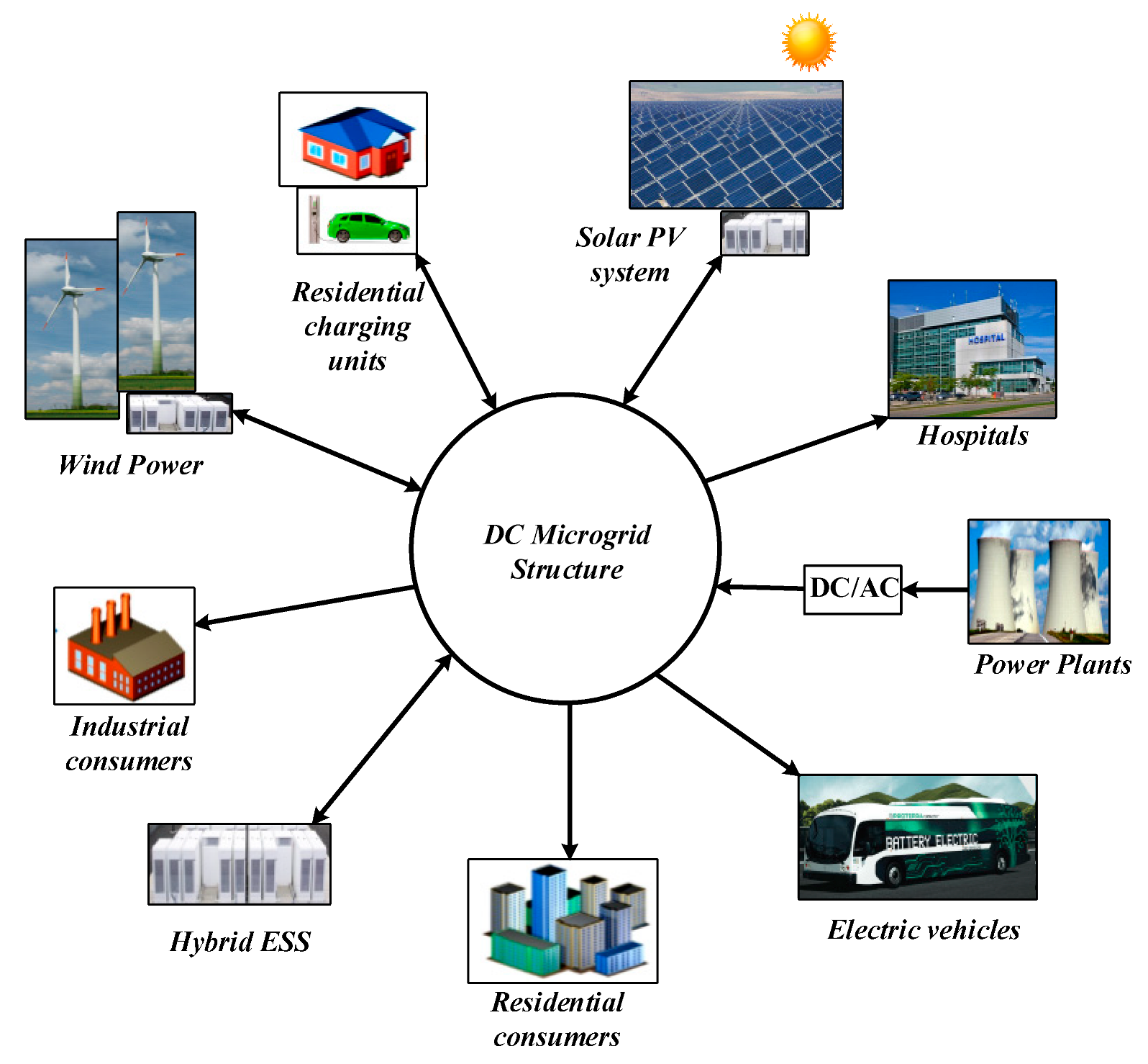
2. System Configuration and Design

Two or more interdependent energy storage systems that are capable of operating as a single unit wherein one surpasses the other, such as batteries, fuel cells, SCs, etc. are known as HESSs. The schematic configuration of a HESS is depicted in Figure 3; it consists of a battery, supercapacitor, and bidirectional boost converter (BBC) for both battery and SC. Figure 4 illustrates the control scheme of a HESS. There are three proportional–integral (PI) controllers used for the voltage control loop and current control loops of the battery and SC, respectively. The voltage control loop regulates grid voltage, whereas the current control loops compensate for the power imbalance between SC and battery during source and load variations.

2.1. Converter Design

The design and analysis of the BBC is carried out in continuous-conduction mode (CCM). Figure 5 shows the steady-state waveforms for the charging–discharging modes of the BBC. Both the battery and the SC have charging–discharging operations, so the BBC is considered [22]. Two BBCs are used to link the battery and SC to the DC microgrid. Each BBC has two switches, with Mb1 and Mb2 for the battery and Ms1 and Ms2 for the SC. The output filter capacitors (Cb and Cs) of the BBCs are considered together as Co. Here, the microgrid is represented as a resistive load RL with grid voltage Vg. The BBCs are connected to the load through a common output capacitor filter, Co. The DC grid is considered to be a constant voltage source with Vg = 24 V. From Figure 3, the voltage across the inductors Lb and Ls is provided by
L b d i L b t d t = V t b
L s d i L s t d t = V t s
where Vtb and Vts are the terminal voltage of battery and supercapacitor, respectively, and Lb and Ls are the inductance of the BBC of battery and SC, respectively. Next, the current through the capacitor is provided by
C b d v g t d t = V g R L
C s d v g t d t = V g R L
where Vg represents the microgrid voltage, and Cb and Cs are the output capacitor filter of battery BBC and SC BBC, respectively. Thus, the values of inductor and capacitor can be found from (1)–(4) as
L b = V g δ b Δ i L b f s
L s = V g δ s Δ i L s f s
C b = V g δ b Δ v g R L f s
C s = V g δ s Δ v g R L f s
where ∆iLb and ∆iLs are the ripple current in the inductor and are taken as 5%, ∆Vg is the capacitor ripple voltage, which is considered as 2%, fs is the switching frequency, δb and δs are the duty cycle of the battery and SC, respectively, and RL represents resistive load.

2.2. Small-Signal Analysis of Boost Converter

The small-signal model of a BBC as depicted in Figure 3 is provided as follows:
L b d i L b t d t = v t b 1 δ b v g
C b d v c b t   d t = 1 δ b i L b v g R L
L s d i L s t d t = v t s c 1 δ s v g
C s d v c s t   d t = 1 δ s i L s v g R L
where Lb and LS are the inductance of the battery converter and SC converter, respectively.
The transfer functions obtained after the small-signal modeling are as follows. The voltage-mode control transfer function:
G v δ b s = v ^ g i ^ L b = 1 δ b v g L b i L b s L b C b s 2 + L b R L s + 1 δ b 2
G v δ s s = v ^ g i ^ L s = 1 δ s v g L s i L s s L s C s s 2 + L s R L s + 1 δ s 2
The current-mode control transfer functions:
G i δ b s = i ^ L b δ ^ b = C b v g s + 2 1 δ b i L b L b C b s 2 + L b R L s + 1 δ b 2
G i δ s s = i ^ L s δ ^ s = C s v g s + 2 1 δ s i L s L s C s s 2 + L s R L s + 1 δ s 2
The output transfer impedance for the battery and SC converters can be obtained from (13)–(16):
G v i b s = v ^ g i ^ L b = 1 δ b v g L b i L b s L b C b s 2 + L b R L s + 1 δ b 2
G v i s s = v ^ g i ^ L s = 1 δ s v g L s i L s s L s C s s 2 + L s R L s + 1 δ s 2

3. Mathematical Modeling

3.1. Battery Model

Lead acid batteries (LAB) are considered to be an ESS. The mathematical model of an LAB represented as a controlled voltage source and internal resistance is shown in the Figure 6.
The controlled voltage source E b a t   can be expressed as [29,30,31]:
E c h a r = E o K Q i t + 0.1 Q . i * K Q Q i t .   i t + E x p t
E d i s c h a r = E o K Q Q i t . i t + i * + E x p t
The terminal voltage of the battery Vtb can be expressed as [29,30]:
V t b = E b a t i R
where Exp(t) represents the exponential zone voltage, I represents current in the battery, E o is constant voltage in the battery, K is the polarization constant, Q is battery capacity, it is actual charge in the battery, A is amplitude of the exponential zone, B is the inverse of the exponential zone time constant, i* is filter current, and RL is the internal resistance of the battery.
The battery SOC is a key factor in the battery’s operation. Battery SOC will vary slower than in an SC. So, the SOC is kept at 50% [30]. The battery discharge characteristics are shown in Figure 7.

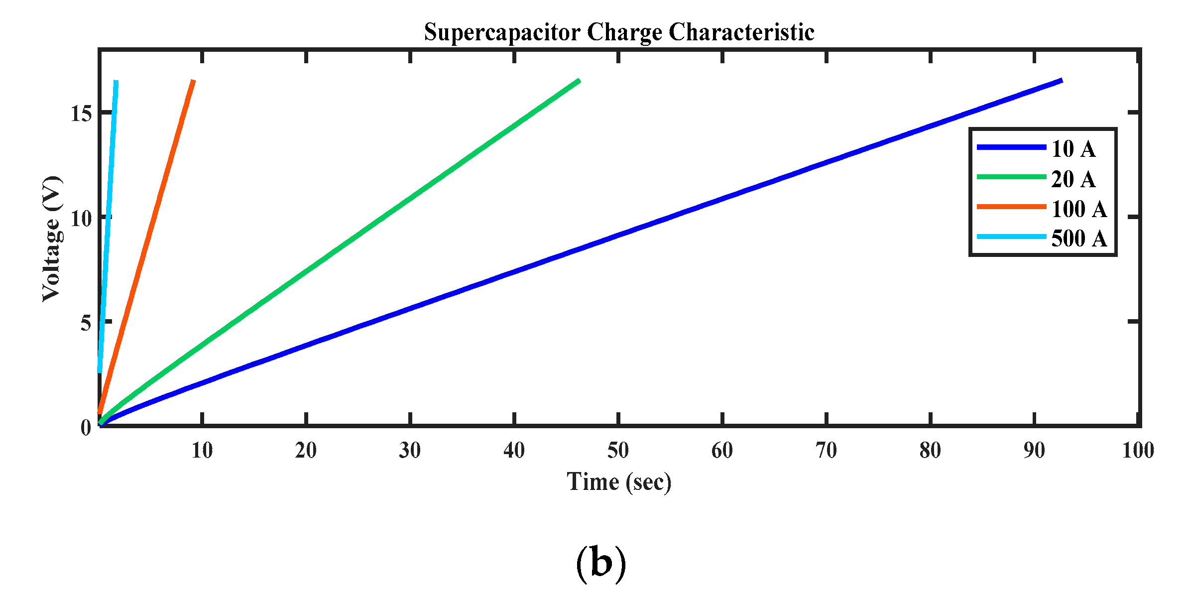
3.2. Supercapacitor Model

The equivalent circuit for the supercapacitor is shown in Figure 8. For a fully charged SC, the SOC will be 100%, and if it is empty, SOC will be 0%. The mathematical model of an SC is obtained by combining the Helmholtz model and the Gouy–Chapman model. The expression for the SOC of an SC is provided below [32,33]:
S O C = Q i n i t i a l 0 t i τ d τ Q T
The total internal charge Q T in coulombs is expressed as [32,33]:
Q T = i s c d t
i t is provided by the expression [33]:
i t = i s c .   1 u t + i s e l f d i s . u t
When i s c = 0, the SC will be self-discharging; then, the Q T is represented as [33]:
Q T = i s e l f d i s d t
The controlled-voltage-source output voltage [33]:
V T = N s Q T d N p N e ϵ ϵ 0 A r + 2 N e N s R T F   s i n h 1 Q T N p N e 2 A r 8 R T ϵ ϵ 0 c
The terminal voltage of SC Vts is obtained from the Stern equation as [33]:
V t s = N s Q T d N p N e ϵ ϵ 0 A r + 2 N e N s R T F   s i n h 1 Q T N p N e 2 A r 8 R T ϵ ϵ 0 c R s c .   i s c
where ε is the permittivity of electrolytic material (Fm−1), ε0 is the permittivity of free space (Fm−1), Ns is a number of SCs connected in series, Np is a number of SCs connected in parallel, Ne is a number of electrode layers, R is the ideal gas constant, T is operating temperature, c is molar constant (mol-m−3), d is the thickness of the Helmholtz layer (m), and iSC is SC current [32,33].

3.3. Controller Design

The role of a controller is crucial in the DC microgrid environment for better power management between the RES and HESS. In this work, the optimal PI-controller-based HESS for a DC microgrid is developed for the effective utilization of renewable power. In this model, the proposed optimal PI controller is developed using the particle swarm optimization approach. The role of the PI controller is to regulate the DC-DC boost converter. The control scheme provides a stable operation between converter characteristics and external uncertainties. A low-pass filter (LPF) is used to perform power-sharing in the HESS, which splits the total current into higher- and lower-frequency components. To reduce the delay in the system, 31 rad/s is chosen as the cut-off frequency of the LPF [2].
The power flow equation of the proposed HESS–DC microgrid system is provided by
P l t = P b t + P s c t + P g t = P a v g t + P ^ t r a n s t
where Pl(t) is the total power of load, Pb(t) is the battery power, Psc(t) is the SC power, Pg(t) is the grid power, Pavg(t) is the total average power, and P ^ trans(t) is the transient power demand that the HESS must supply or absorb from the DC microgrid to balance the load conditions and maintain the DC microgrid power as constant.
The general form of the PI controller is provided by
P I x = K p x + K i x s

3.4. PSO Algorithm

The PSO algorithm is a multi-agent parallel-search technique which maintains a swarm of particles, with each particle in the swarm representing a potential solution [23]. It was developed by Eberhart and Kennedy in 1995, and is inspired by the behavior of birds and fish swarms. In PSO, all the randomly initiated particles are evaluated, and the fitness is computed together with the best values of each particle and the entire swarm. Then, a loop searches for an optimal solution. In the loop, the particle’s velocity is updated first by the personal and global best values; then, the current velocity will update the position of the particle. This can be illustrated by the equation
V j t + 1 = w * V j t + C 1 r 1 p j X j t + C 2 r 2 p g X j t
where t is the iteration number, j is the particle number, the personal best value of particle j at a given stage is represented by the vector pj, the global best values calculated from all the particles at t is represented by the vector pg, C1 and C2 are the acceleration parameters, and vectors r1 and r2 are uniformly distributed random variables which have values between 0 and 1. The current velocity updates the particle positions to attain an optimal solution as shown below:
X j t + 1 = X j t + V j t + 1  
The PSO algorithm has a lot of advantages, as it has very simple calculations and is an algorithm without a derivative. It has a limited number of parameters which have less impact on the solution, and is easy to implement [23]. Figure 9 shows the PSO tuning of the PI controller. In this paper, the PSO algorithm which is used to determine the optimal values of parameters of the PI controller has already been designed. The integral square value of error (ISE) is the objective function used. It is based on the error obtained from the input–output comparison. The maximum value of every computation is the updated value of the next stage. If e(t) represents the voltage-tracking error at a particular instant of time t, then ISE can be expressed as:
I S E = 0 e 2 t d t

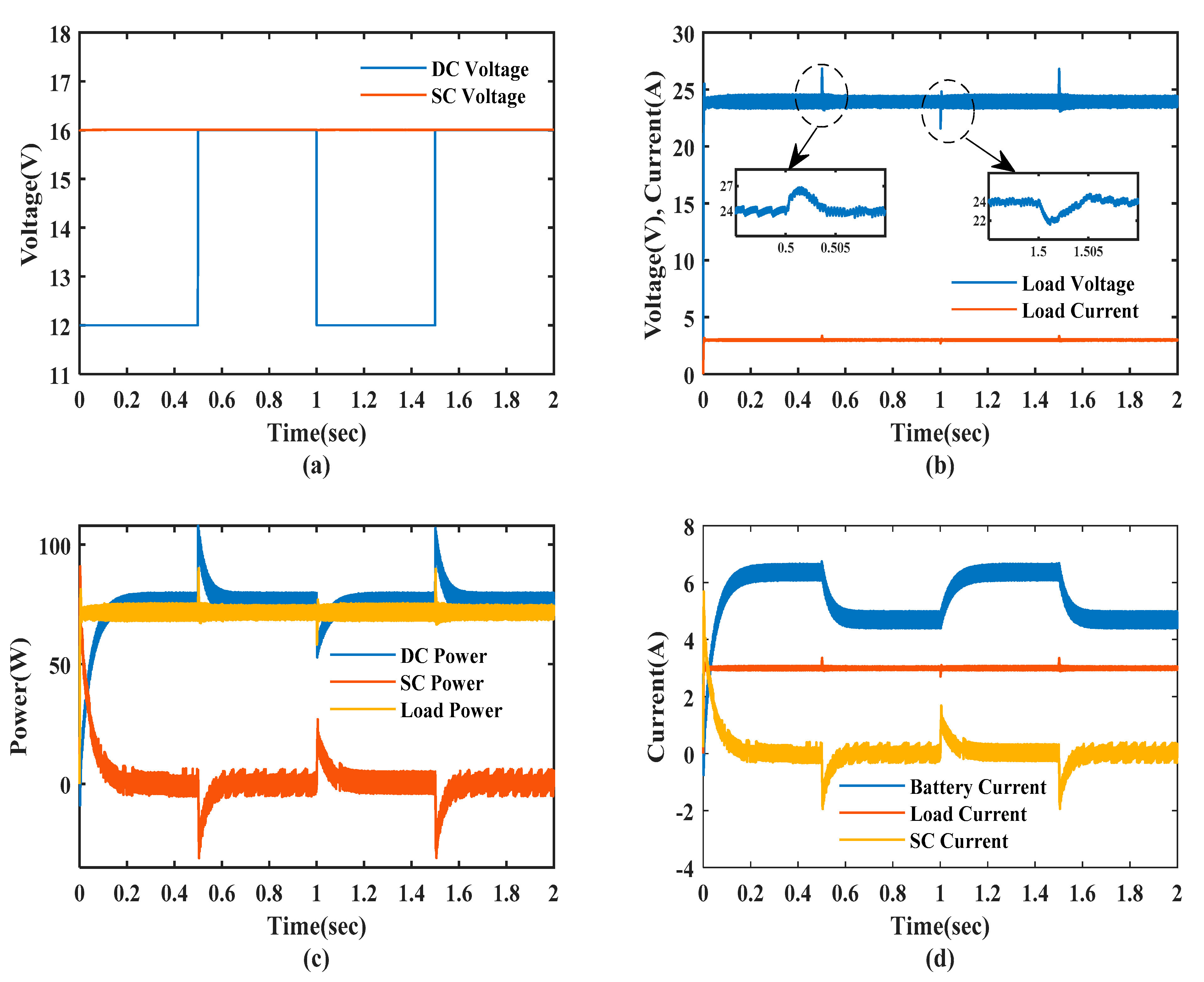
4. Results and Discussions

To validate the analysis and to evaluate the performance of a PI-controller-based HESS and optimal PI-controller-based HESS, simulations are carried out using MATLAB/Simulink platform. A controlled DC voltage source is considered as the main DC bus to study the performance of a HESS for line and load perturbations. The design specifications of bidirectional boost converters for both the battery and SC are illustrated in Table 2.
Figure 10 and Figure 11 depict the simulation waveforms of the conventional PI controller and the proposed optimal PI-controller-based HESS with a sudden increase and decrease in source voltage at 0.5 s and 1 s, respectively. The source voltage of 12 V is offered at t = 0 s, and at time t = 0.5 s there is a sudden increase in the source voltage from 12 V to 16 V. At this instant, there is a sudden fluctuation in the load voltage which leads to an imbalance between DC grid power and load power. Under such conditions, the load current increases while the requirement of load power is constant at 72 W. As power supplied by the source during a sudden increase in voltage is more than the power demanded by the load, and DC grid voltage increases more than 24 V, The excess power is absorbed by the SC for a short duration until the grid voltage is regulated to 24 V by the battery. Thus, by this energy-management scheme, the battery and SC charge accordingly in order to maintain the constant grid voltage at 24 V. Further, during this period of time, the SC compensates for the power, and thus, reduces the burden on the battery.
From the simulation results, it can clearly be seen that the settling time for the conventional PI-controller-based HESS is around 30 m whereas the settling time of 6 m is achieved with the proposed optimal PI-controller-based HESS, which resulted in faster dynamic response and better DC grid regulation with of the proposed optimal PI controller for a sudden increase in source voltage. Similarly, a sudden decrease in source voltage from 16 V to 12 V at t = 1 s results in load current decreases, while the requirement of load power is constant at 72 W. As power supplied by the source during a sudden decrease in source voltage is less than the power demanded by load, and DC grid voltage decreases less than 24 V, SC supplies the deficit power for a short duration until the battery can regulate the grid voltage to 24 V. Under this condition, the settling times for the conventional PI and optimal PI controller are 25 m and 5 m, respectively. From the simulation results, it clearly shows that the proposed optimal PI-controller-based HESS has better performance than the conventional PI controller for source disturbance. Further, the proposed optimal PI controller is 5 times faster than the conventional PI controller.
Figure 12 and Figure 13 show the simulation waveforms of the conventional PI controller and the proposed optimal PI-controller-based HESS with a sudden increase and decrease in load demand at t = 0.4 s and t = 1 s, respectively. The load current of 1 A is offered at t = 0 s; at time t = 0.4 s there is a sudden increase in the load current from 1 A to 2 A. At this instant, there is a sudden fluctuation in the load voltage which leads to an imbalance between DC grid power and load power. During this period of time, the SC compensates for the power, and thus, reduces the burden on the battery. Then, the voltage is restored to its actual value, that is, 24 V. The response time for the conventional PI-controller-based HESS with a sudden increase in load disturbance is around 14 m, whereas a response time of 8 m is achieved with the optimal PI controller, which results in a faster response for the HESS to the load disturbance.
Further, the sudden decrease in load current is introduced at t = 1 s, and the voltage spike due to the load change is restored to its actual value, with a response time for the conventional PI-controller-based HESS around 13 m and a response time of 7 m achieved with the optimal PI controller. From the simulation results, it is clearly shown that the proposed optimal PI-controller-based HESS has better performance than the conventional PI controller for load disturbance. Further, the proposed optimal PI-controller is two times faster than a conventional PI controller.
The performance parameters such as settling time and maximum peak overshoot are evaluated for the conventional PI controller and proposed optimal PI-controller-based HESS with source and load disturbance. The peak overshoot during source disturbance and load disturbance is evaluated as follows.
% M P = V g , r e f V g , m a x V g , r e f
Figure 14 illustrates the performance evaluation of the conventional and proposed optimal PI controllers. The advantages of the proposed control over conventional control are depicted in the graph. The proposed controller is five times faster in response during source variations. Under varying load conditions, the proposed controller is two times faster compared to the conventional one. The percentage voltage overshoot is improved under increasing values of source voltage and load. In Case II, the source voltage is decreased, causing reduction in the grid voltage to the nominal value. Thus, HESS regulates the power, and there is a voltage undershoot of 9.5% and 10.1% for a short duration with the conventional and proposed controllers. For the proposed controller, undershooting is slightly more than that of the conventional controller.
In case IV, the DC-grid-side load is back to the rated load condition, which leads to an increase in grid voltage. This causes an overshoot of 11.6% and 12.5% for the conventional and proposed controllers for a short duration. This is settled within milliseconds. Thus, the proposed controller overshoot is slightly more than that of the conventional controller. From the above results, it can be noted that the improvement in response time is greater with the proposed controller. Conversely, the peak undershoots during a sudden reduction of load and source are marginal for the proposed control method.

5. Conclusions

In this paper, the optimal PI control for a HESS-based DC microgrid is developed for effective power management. The modeling, analysis, and design of BBCs are carried out. The optimal PI controller is designed for a BBC with battery and SC as storage devices. The performance of the proposed optimal PI-controller-based HESS is analyzed with changes in source and load variations. The controller effectively regulates the DC grid voltage with changes in source and load variations. The effectiveness of the proposed optimal PI controller is compared with the conventional PI controller strategy for HESS. Simulation results show the settling time has been reduced sharply and improved peak overshoot. The proposed optimal PI controller has robustness during load and source uncertainties. Subsequent work will address the proposed controller feasibility for various DC-DC converter topologies in HESS applications, and propose controllers for different RESs.

Author Contributions

Conceptualization, M.V. and R.R.U.; Data curation, M.V., R.R.U. and B.L.; Formal analysis, M.V., R.R.U. and T.M. and B.S.G.; Funding acquisition, S.P. and B.T.; Investigation, M.V., R.R.U., B.L., C.N.S.K. and P.K.B.; Methodology, M.V. and R.R.U.; Project administration, R.R.U., D.C., S.P. and B.T.; Resources, R.R.U. and B.T.; Software, M.V. and D.C.; Supervision, R.R.U. and B.T.; Validation, M.V.; Writing—original draft, M.V., R.R.U., T.M., B.L.; Writing—review & editing, R.R.U., T.M. and B.L. All authors have read and agreed to the published version of the manuscript.

Funding

This research received no external funding.

Institutional Review Board Statement

Not applicable.

Informed Consent Statement

Not applicable.

Data Availability Statement

Not applicable.

Conflicts of Interest

The authors declare no conflict of interest.

References

  1. Ortuzar, M.; Moreno, J.; Dixon, J. Ultracapacitor-Based Auxiliary Energy System for an Electric Vehicle: Implementation and Evaluation. IEEE Trans. Ind. Electron. 2007, 54, 2147–2156. [Google Scholar] [CrossRef]
  2. Song, M.-S.; Son, Y.-D.; Lee, K.-H. Non-isolated Bidirectional Soft-switching SEPIC/ZETA Converter with Reduced Ripple Currents. J. Power Electron. 2014, 14, 649–660. [Google Scholar] [CrossRef] [Green Version]
  3. Bayat, H.; Yazdani, A. A Hybrid MMC-Based Photovoltaic and Battery Energy Storage System. IEEE Power Energy Technol. Syst. J. 2019, 6, 32–40. [Google Scholar] [CrossRef]
  4. Ibanez, F.M.; Florez, A.M.B.; Gutierrez, J.S.; Echeverrria, J.M. Extending the Autonomy of a Battery for Electric Motorcycles. IEEE Trans. Veh. Technol. 2019, 68, 3294–3305. [Google Scholar] [CrossRef]
  5. Choudhury, T.R.; Nayak, B.; De, A.; Santra, S.B. A comprehensive review and feasibility study of DC-DC converters for different PV applications: ESS, future residential purpose. EV Charg. Energy Syst. 2020, 11, 641–671. [Google Scholar] [CrossRef]
  6. Dougal, R.A.; Liu, S.; White, R.E. Power and life extension of battery, ultracapacitor hybrids. IEEE Trans. Compon. Packag. Technol. 2002, 25, 120–131. [Google Scholar] [CrossRef] [Green Version]
  7. Lu, D.; Fakham, H.; Zhou, T.; Francois, B. Application of petri nets for the energy management of a photovoltaic based power station including storage units. Renew. Energy 2010, 35, 1117–1124. [Google Scholar] [CrossRef]
  8. Garcia, O.; Zumel, P.; de Castro, A.; Cobos, A. Automotive DC-DC bidirectional converter made with many interleaved buck stages. IEEE Trans. Power Electron. 2006, 21, 578–586. [Google Scholar] [CrossRef]
  9. Zhao, B.; Song, Q.; Liu, W.; Sun, Y. Overview of dual-activebridge isolated bidirectional DC–DC converter for high-frequency-link power-conversion system. IEEE Trans. Power Electron. 2014, 29, 4091–4106. [Google Scholar] [CrossRef]
  10. Lahyani, A.; Venet, P.; Guermazi, A.; Troudi, A. Battery/Supercapacitors Combination in UPS. IEEE Trans. Power Electron. 2013, 28, 1509–1522. [Google Scholar] [CrossRef]
  11. Vazquez, S.; Lukic, S.M.; Galvan, E.; Franquelo, L.G.; Carrasco, J.M. Energy storage systems for transport and grid applications. IEEE Trans. Ind. Electron. 2010, 57, 3881–3895. [Google Scholar] [CrossRef] [Green Version]
  12. Kollimalla, S.K.; Mishra, M.K.; Ukil, A.; Gooi, H.B. DC grid voltage regulation using new HESS control strategy. IEEE Trans. Sustain. Energy 2016, 8, 772–781. [Google Scholar] [CrossRef]
  13. Kanchev, H.; Lu, D.; Colas, F.; Lazarov, V.; Francois, B. Energy Management and Operational Planning of a Microgrid With a PV-Based Active Generator for Smart Grid Applications. IEEE Trans. Ind. Electron. 2011, 58, 4583–4592. [Google Scholar] [CrossRef] [Green Version]
  14. Arunkumar, C.R.; Manthati, U.B. Design and Small Signal Modeling of Battery-Supercapacitor HESS for DC Microgrid. In Proceedings of the TENCON 2019–2019 IEEE Region 10 Conference (TENCON), Kochi, India, 17–20 October 2019; pp. 2216–2221. [Google Scholar]
  15. Tummuru, N.R.; Mishra, M.K.; Srinivas, S. Dynamic energy management of HESS with high-gain PV converter. IEEE Trans. Energy Convers. 2015, 30, 150–160. [Google Scholar] [CrossRef]
  16. Kim, S.; Chou, P.H. Energy Harvesting with Supercapacitor-Based Energy Storage. In Smart Sensors and Systems; Springer: Cham, Switzerland, 2015; pp. 215–241. [Google Scholar]
  17. Huang, W.; Abu Qahouq, J.A. Energy Sharing Control Scheme for State-of-Charge Balancing of Distributed Battery Energy Storage System. IEEE Trans. Ind. Electron. 2014, 62, 2764–2776. [Google Scholar] [CrossRef]
  18. Hredzak, B.; Agelidis, V.G.; Demetriades, G.D. A Low Complexity Control System for a Hybrid DC Power Source Based on Ultracapacitor–Lead–Acid Battery Configuration. IEEE Trans. Power Electron. 2013, 29, 2882–2891. [Google Scholar] [CrossRef]
  19. Rani, B.I.; Ilango, G.S.; Nagamani, C. Control Strategy for Power Flow Management in a PV System Supplying DC Loads. IEEE Trans. Ind. Electron. 2012, 60, 3185–3194. [Google Scholar] [CrossRef]
  20. García, P.; Torreglosa, J.P.; Fernández, L.M.; Jurado, F. Optimal energy management system for stand-alone wind turbine/photovoltaic/hydrogen/battery hybrid system with supervisory control based on fuzzy logic. Int. J. Hydrogen Energy 2013, 38, 14146–14158. [Google Scholar] [CrossRef]
  21. Mardani, M.M.; Khooban, M.H.; Masoudian, A.; Dragicevic, T. Model Predictive Control of DC–DC Converters to Mitigate the Effects of Pulsed Power Loads in Naval DC Microgrids. IEEE Trans. Ind. Electron. 2018, 66, 5676–5685. [Google Scholar] [CrossRef] [Green Version]
  22. Manandhar, U.; Tummuru, N.R.; Kollimalla, S.K.; Ukil, A.; Beng, G.H.; Chaudhari, K. Validation of Faster Joint Control Strategy for Battery- and Supercapacitor-Based Energy Storage System. IEEE Trans. Ind. Electron. 2017, 65, 3286–3295. [Google Scholar] [CrossRef]
  23. Abdelmalek, S.; Dali, A.; Bettayeb, M.; Bakdi, A. A new effective robust nonlinear controller based on PSO for interleaved DC–DC boost converters for fuel cell voltage regulation. Soft Comput. 2020, 24, 17051–17064. [Google Scholar] [CrossRef]
  24. Arunkumar, C.R.; Manthati, U.B.; Srinivas, P. Accurate modelling and analysis of battery–supercapacitor hybrid energy storage system in DC microgrid systems. Energy Syst. 2021, 13, 1055–1073. [Google Scholar] [CrossRef]
  25. Scarabaggio, P.; Carli, R.; Dotoli, M. Noncooperative Equilibrium Seeking in Distributed Energy Systems Under AC Power Flow Nonlinear Constraints. IEEE Trans. Control Netw. Syst. 2022, 1–12. [Google Scholar] [CrossRef]
  26. Carli, R.; Cavone, G.; Pippia, T.; De Schutter, B.; Dotoli, M. Robust Optimal Control for Demand Side Management of Multi-Carrier Microgrids. IEEE Trans. Autom. Sci. Eng. 2022, 19, 1338–1351. [Google Scholar] [CrossRef]
  27. Karimi, H.; Jadid, S. Optimal energy management for multi-microgrid considering demand response programs: A stochastic multi-objective framework. Energy 2020, 195, 116992. [Google Scholar] [CrossRef]
  28. Yao, M.; Molzahn, D.K.; Mathieu, J.L. An Optimal Power-Flow Approach to Improve Power System Voltage Stability Using Demand Response. IEEE Trans. Control Netw. Syst. 2019, 6, 1015–1025. [Google Scholar] [CrossRef]
  29. Talukder, S. Mathematicle Modelling and Applications of Particle Swarm Optimization. Master’s Thesis, Mathematical Modelling and Simulation. Blekinge Institute of Technology, Karlskrona, Sweden, 2011. Thesis No.: 2010:8. [Google Scholar]
  30. Mathworks. Implement Generic Battery Model-Simulink-MathWorks United Kingdom. Available online: http://www.mathworks.co.uk/help/physmod/powersys/ref/battery.html (accessed on 9 February 2020).
  31. Tremblay, O.; Dessaint, L.-A. Experimental Validation of a Battery Dynamic Model for EV Applications. World Electr. Veh. J. 2009, 3, 289–298. [Google Scholar] [CrossRef] [Green Version]
  32. Mathworks. Implement Generic Supercapacitor Model-Simulink-MathWorks India. Available online: https://in.mathworks.com/help/physmod/sps/powersys/ref/supercapacitor.html (accessed on 9 February 2020).
  33. Oldham, K.B. A Gouy–Chapman–Stern model of the double layer at a (metal)/(ionic liquid) interface. J. Electroanal. Chem. 2008, 613, 131–138. [Google Scholar] [CrossRef]
Figure 1. Structure of a DC microgrid.
Sustainability 14 14666 g001
Figure 2. Various hybrid ESS configurations (a,b) passive configuration, (c,d) semi-active configuration, (e,f) active configuration.
Sustainability 14 14666 g002
Figure 3. Schematic of HESS in active configuration.
Sustainability 14 14666 g003
Figure 4. Control scheme of HESS.
Sustainability 14 14666 g004
Figure 5. Steady-state waveforms of HESS charging–discharging modes.
Sustainability 14 14666 g005
Figure 6. Equivalent circuit of lead acid battery.
Sustainability 14 14666 g006
Figure 7. Discharge characteristics of 12 V, 7 Ah lead acid battery.
Sustainability 14 14666 g007
Figure 8. (a) Equivalent circuit of SC, (b) SC charge characteristics.
Sustainability 14 14666 g008aSustainability 14 14666 g008b
Figure 9. Block diagram representation of the PSO-based controller.
Sustainability 14 14666 g009
Figure 10. Performance comparison of conventional control strategy for sudden changes in source voltage: (a) DC voltage and SC voltage, (b) load voltage and load current, (c) DC power, SC power, and load power, (d) battery current, load current, and SC current.
Sustainability 14 14666 g010
Figure 11. Performance comparison of proposed optimal PI control strategy for sudden changes in source voltage: (a) DC voltage and SC voltage, (b) load voltage and load current, (c) DC power, SC power, and load power, (d) battery current, load current, and SC current.
Sustainability 14 14666 g011
Figure 12. Performance comparison of conventional control strategy for sudden changes in load: (a) load voltage and load current, (b) battery current, load current, and SC current, (c) DC power, SC power, and load power, (d) battery voltage and SC voltage.
Sustainability 14 14666 g012
Figure 13. Performance comparison of proposed optimal PI control strategy for sudden changes in load: (a) load voltage and load current, (b) battery current, load current, and SC current, (c) DC power, SC power, and load power, (d) battery voltage and SC voltage.
Sustainability 14 14666 g013
Figure 14. Performance comparison of conventional control strategy with proposed optimal PI control strategy: (a) Settling time, (b) Voltage overshoot.
Sustainability 14 14666 g014
Table 1. Parameter comparison of battery and SC.
ParametersBatterySupercapacitor
Recharge cycle lifetime< 10 3 cycles> 10 6 cycles
Self-discharge rate5%30%
Voltage3.7 V–4.2 V0 V–2.7 V
Energy density (Wh/kg)High (20–150)Low (0.8–10)
Power density (W/kg)Low (50–300)High (500–400)
Fastest charging timeHourss~min
Fastest discharging time0.3~3 h<a few min
Charging circuitComplexSimple
Table 2. Parameters of the Hybrid ESS unit.
System ParametersValues
Battery voltage (Vb)12 V
SC voltage (VSC)16 V
Load resistance (RL)8 Ω
Inductance of battery converter (Lb)2 mH
Inductance of SC converter (LS)1.8 mH
Output capacitor filter values (Co)250 μF
Power output (Pdc)72 W
Switching frequency (fs)20 kHz
Output voltage (Vdc)24 V
Publisher’s Note: MDPI stays neutral with regard to jurisdictional claims in published maps and institutional affiliations.

