
Analysis of Control Methods for the Traction Drive of an Alternating Current Electric Locomotive
by
 ,
,
Sergey Goolak
1, 
Viktor Tkachenko
1,
Pavol Šťastniak
2,*,
Svitlana Sapronova
3 and
Borys Liubarskyi
4 1
Department of Electromechanics and Rolling Stock of Railways, State University of Infrastructure and Technologies, Kyrylivska Str., 9, 04071 Kyiv, Ukraine
2
Department of Transport and Handling Machines, University of Žilina, Univerzitná 8215/1, 010 26 Žilina, Slovakia
3
Department of Cars and Carriage Facilities, State University of Infrastructure and Technologies, Kyrylivska Str., 9, 04071 Kyiv, Ukraine
4
Department of Electrical Transport and Diesel Locomotive, National Technical University «Kharkiv Polytechnic Institute», Kyrpychova Str., 2, 61002 Kharkiv, Ukraine
*
Author to whom correspondence should be addressed.
Symmetry 2022, 14(1), 150; https://doi.org/10.3390/sym14010150
Submission received: 3 November 2021
/
Revised: 21 December 2021
/
Accepted: 4 January 2022
/
Published: 13 January 2022
(This article belongs to the Special Issue Symmetry and Asymmetry Principles in Latest Advances and Prospects of the Materials Science and Engineering)
Abstract
:The analysis of operating conditions of traction drives of electric locomotives with asynchronous traction motors has been carried out. It was found that during operation in the output converter of an asynchronous motor, defects may occur, which leads to asymmetric modes of its operation. Models of a traction drive of an electric locomotive with asynchronous motors with scalar and vector control of the output converter are proposed, taking into account asymmetric operating modes. As a result of the simulation, the starting characteristics of the traction drive were obtained for various control methods both in normal and emergency modes of the drive. For the drive-in emergency mode, the following cases were investigated: the balance of the converter output voltages and the turn-to-turn circuit of 10% of phase A winding of the motor stator; imbalance of the output voltages of the inverter and an intact motor; imbalance of the output voltages of the converter and interturn short circuit of 10% of phase A winding of the motor stator. Comparison of the simulation results have shown that in emergency modes in the traction drive, the torque ripple on the motor shaft in the drive with vector control is 13% less, and in scalar control, the phase current unbalance coefficient is 22% less. The results of this work can be used to study the influence of the output converter control methods on the energy efficiency indicators of the traction drive of an AC electric locomotive.
1. Introduction
Reducing operating losses is a major challenge for optimal rail transport management. A lot of research has been devoted to this problem. For example, works [1,2,3] are devoted to the study of resistance to motion by improving the design of wheelsets. The influence of the car design on energy losses during movement is considered in articles [4,5]. The work [6] discusses the issues of increasing the reliability of structural elements and the traction drive of crews. The processes in the traction drive of an electric locomotive on curved track sections were investigated in [7].
The traction drive of an electric locomotive is the most complex and energy-intensive element of a railway rolling stock. A topological overview of the rolling stock architecture and the concept of the quality of traction power supply for railways are considered in the article [8]. This work indicates that the traction drive of modern electric locomotives is built on the basis of an asynchronous traction motor. Further, the directions of the development of traction drive control systems are shown in this work. However, the issues of constructing traction drive control systems and the influence of the traction drive on the power quality indicators in this work are considered only conceptually. To reduce the negative impact of the operation of the traction electric drive on the traction power supply system, and, consequently, to increase the power factor of the traction drive, it is proposed to use on-board energy storage devices. The article also does not study the influence of the operation of a traction drive with energy storage devices on the quality indicators of traction power supply.
Studies of the energy efficiency of traction rolling stock with electric energy storage units can be contained in works [9,10]. Despite the obviously correct results concerning the issues of increasing the power factor of the traction drive, these works do not show how the proposed solutions will affect the drive efficiency. This question is relevant since additional devices in the drive lead to an increase in power loss.
This issue was investigated in the article [11], which is devoted to the determination of the optimal operating modes of the traction drive. In it, the authors proposed to optimize the power factor and efficiency according to the criterion of maximum energy efficiency.
In [11], the issues of the influence of the quality of power supply of the traction drive and modes of its operation on energy efficiency are not considered. The problem of the quality of power supply of the traction drive of an electric locomotive is also considered in [12]. It is shown in the work that the process of voltage change in the contact network is stochastic. The works [13,14,15] are devoted to the study of the influence of the operating modes of the electric rolling stock on the voltage parameters of the contact network. In particular, work [15] shows that the magnetic losses in the steel of the traction motor depend on the rotational speed of the motor shaft. The analysis of the listed works proves that the power factor and efficiency of the traction drive depend on the operating modes of the electric rolling stock.
In an asynchronous traction drive, the control system is responsible for the quality of control and optimization of operating modes. In work [8], it is indicated that in drives with an asynchronous traction motor, control systems can be of the following types:
- -
- Scalar.
- -
- Vector.
- -
- With direct torque control.
Scalar control systems for an asynchronous drive [16,17], in comparison with vector systems and systems with direct torque control, have a simpler structure and higher performance. However, they can only control one channel—torque. Due to the asymmetric modes of stator currents during starting of the traction motor and at low rotation frequency, the significant ripple of the motor torque can occur. This, in turn, is the reason for the reduced power factor of the drive and increased dynamic loads in the drive elements. In [17], it was proposed to use a damper to damp the torque pulsations on the shaft.
In systems with a vector type of control [18,19,20], control is carried out via two channels—speed and flux linkage. In this regard, in systems with vector control, it is possible to spread control over these channels in time. In this case, the flux linkage control channel operates first, and the speed control channel is turned on after that. This makes it possible to significantly reduce electromagnetic oscillations in the traction drive at a low speed of the traction motor. Slow response to a change in the moment of resistance of the traction drive is a drawback of the vector-type control system. This factor is important for traction drive control, since, in the operation of electric rolling stock, the change in the moment of resistance occurs frequently. This is due to the stochastic nature of the adhesion coefficient and dynamic processes in the wheel-rail contact.
Traction drive with direct torque control [21,22,23] allows you to most effectively solve this problem. In these systems, control, as well as in vector systems, is carried out through two channels—flux linkage and electromagnetic torque. The introduction of a torque control link into the control system makes it possible to quickly respond to changes in the resistance moment and, thereby, to provide more accurate control of the traction drive.
The listed works show the advantages and disadvantages of various types of asynchronous drive control. The work is based on the hypothesis of strict symmetry of the traction drive windings and the converter arms. However, during operation, various types of malfunctions can occur in the traction drive, which can lead to asymmetric modes of operation of the traction motor or power converter.
In works [24,25,26], it is shown that in operation, the parameters of power transistors of the output converter of an electric locomotive traction drive often deviate from the nominal value. Moreover, as a rule, these deviations are asymmetric with respect to different arms of the converter. This leads to the emergence of asymmetric modes of the power supply system of traction motors. This, in turn, leads to a ripple of the motor torque and imbalance of the stator phase currents even in the steady-state operation of the traction drive.
In operation in traction motors, asymmetry of the stator windings may occur, caused by such a defect as interturn short circuit [27,28,29]. Unbalanced stator windings also lead to ripple in motor torque and imbalance in stator phase currents. Thus, both the asymmetric modes of the traction motor power supply system and the asymmetry of its windings lead to an increase in losses in the electric locomotive traction drive. The consequence of this is a decrease in the energy parameters of the traction drive, such as power factor and efficiency.
Thus, the study of the influence of asymmetric modes of the power supply system and the asymmetry of the traction motor windings on the operation of the AC traction drive is relevant.
The aim of the study is to analyze the efficiency of scalar and vector control of the output converter of the traction drive of an AC electric locomotive in normal and asymmetric operating modes.
To accomplish the task, the following was completed:
- -
- Selection of a mathematical model of a traction motor, which allows us to investigate the operation of the motor in the presence of asymmetry in its windings and in the presence of asymmetry in the power supply system.
- -
- Simulation of the control system of the output converter with scalar and vector control.
- -
- Received starting characteristics for scalar and vector traction drive control system for normal operation.
- -
- The starting characteristics were obtained for the scalar and vector traction drive control system for the emergency (asymmetric) mode: (1) in the traction motor; (2) in the output converter; (3) simultaneously in the traction motor and the output converter.
- -
- The comparison of the obtained starting characteristics.
This work can be used in the study of the energy efficiency of the traction drive of AC electric locomotives, in the study of the interaction between the contact network and the electric rolling stock, in the calculation of optimal control systems for the traction drive of the electric rolling stock.
2. Materials and Methods
Investigations of the operation of an asynchronous traction drive with various control systems of the output inverter were carried out on the basis of a mathematical model, the equations of which are written in three-phase coordinates. These equations were supplemented with equations allowing us to take into account the change in the values of the mutual phase inductances and the main inductance of the magnetizing circuit when changing the geometry of the winding stator.
A simulation model of a traction drive with various control systems for the output inverter is implemented in the MATLab software. In the study of the starting characteristics of the traction drive on the simulation model, eight numerical experiments were carried out. The first experiment consisted in obtaining starting characteristics for a traction drive with a scalar control system, which operates in a normal mode. The second one is for the same drive, provided that a turn-to-turn closure of 10% of the winding occurred on phase A of the stator of the traction motor winding. The third is for the same drive, provided that the resistance of one of the power transistors of phase B of the output converter has decreased by 2%. The fourth—for the same drive, provided that on phase A of the stator of the traction motor winding, there was an interturn short circuit of 10% of the winding and the resistance of one of the power transistors of phase B of the output converter decreased by 2%. The fifth, sixth, seventh, and eighth experiments were carried out similarly to the first, second, third, and fourth experiments, only with a vector control system. The starting characteristics of the traction drive with different control systems were compared: the results of the first and fifth, second and sixth, third and seventh, and fourth and eighth experiments.
The object of research is an AC electric locomotive with an asynchronous traction motor of the DS-3 series (country of origin—Ukraine). The technical characteristics of the electric locomotive are presented in Table 1 [30].
The rest of the parameters required for the implementation of simulation models of the traction drive were obtained as a result of calculations and are given below.
3. Results of the Analysis of Control Methods for the Output Converter of the Traction Drive of an AC Electric Locomotive
3.1. Justification of the Choice of a Mathematical Model of an Induction Motor
There are many models of induction motors described in various studies. Each model is designed to solve a particular problem. On the one hand, it would be logical to use a model of an asynchronous motor in two-phase αβ or dq coordinates. This is useful when building a vector control system. On the other hand, to implement the set task of studying the processes in the traction drive in the presence of asymmetric modes in the traction motor, one should choose a mathematical model in a three-phase coordinate system. In addition, the model should work adequately in the presence of asymmetric modes in the power supply system. To accomplish these tasks, the model described in the study [31] is suitable. This model is implemented in the MATLab software environment. The electrical part of the model is made using electrical elements. This will allow the study of asymmetric modes in the presence of asymmetry in the power supply system. The magnetic and mechanical parts are realized with structural elements. This allows, using the methodology given in the study [32], to investigate the operation of the motor in the presence of asymmetry in its windings.
3.2. Simulation of the Control System of the Output Converter with Scalar and Vector Control
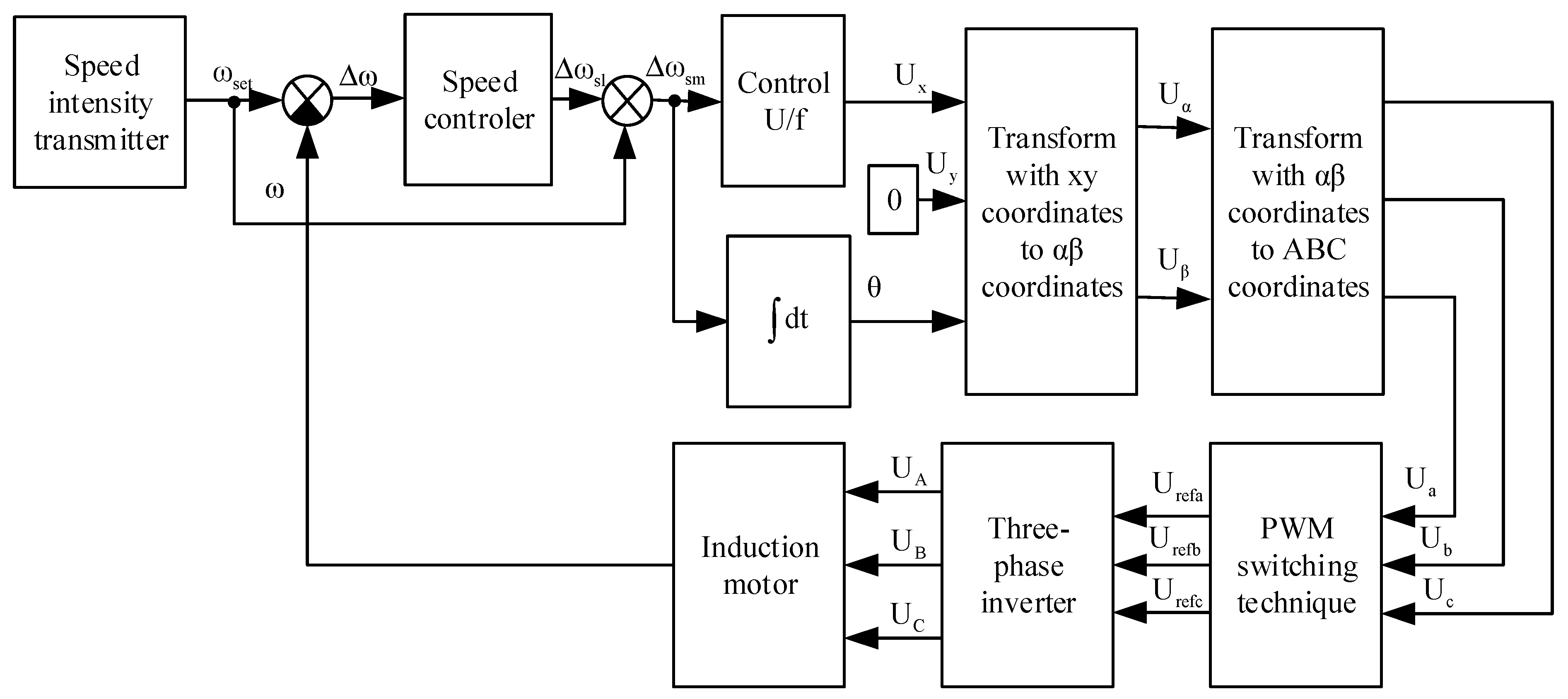
The block diagram of the scalar control system is presented in the study [23] and is shown in Figure 1.
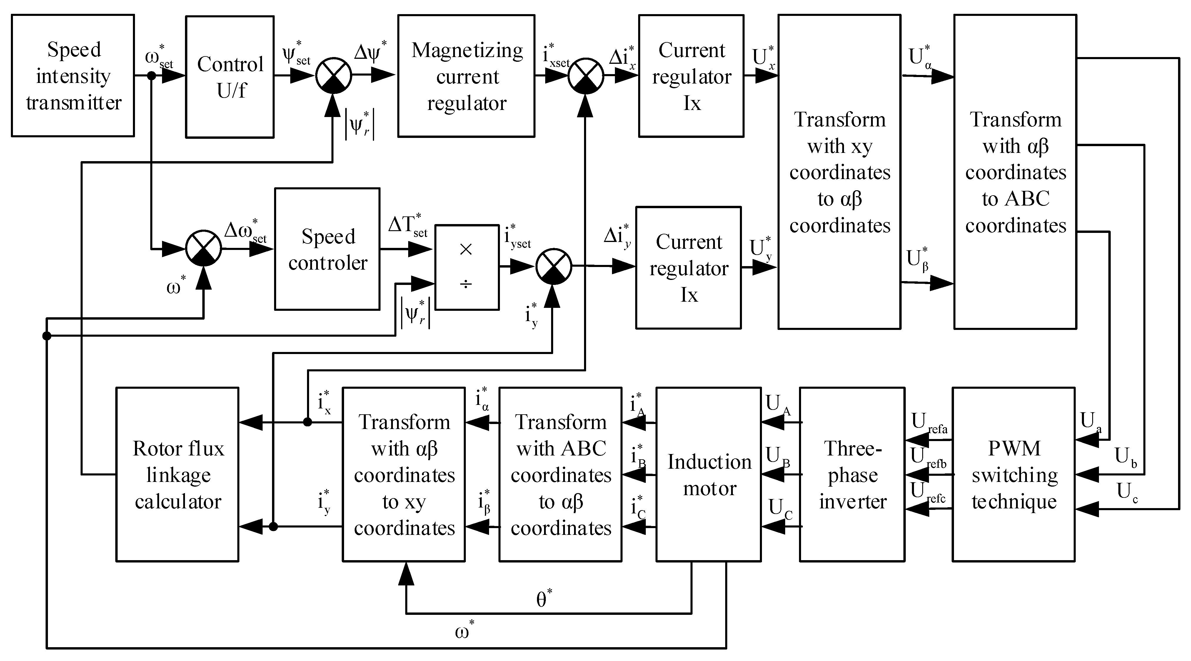
The block diagram of the vector control system is presented in the study [24] and is shown in Figure 2.
In the structural diagrams of scalar (Figure 1) and vector control (Figure 2), a speed intensity regulator was used. It was calculated based on the following considerations. When starting off an electric locomotive, its acceleration should not exceed the boundary acceleration. The boundary acceleration is determined from the conditions for solving the traction problem [33]
where FT is locomotive pulling force when starting off (Figure 1).
a = FT/m = 27523/90000 = 0.306, m/s2,
m—locomotive weight (Table 1).
The angular acceleration, converted to the motor shaft, is determined by the expression
where μr—gear ratio (Table 1).
dω/dt= (a·μr)/(R·ηr) = (0.306·4.105)/(0.6·0.955) = 2.192, rad/s2,
R—wheel radius (Table 1).
ηr—gearbox efficiency.
Time to reach the set rotation speed
where ωset—set value of the electric angular speed of rotation of the motor shaft.
tset = ωset/(dω/dt),
Then the equation describing the work of the speed intensity generator has the form
ω = (dω/dt)·t, at 0 < t < tset,
ω = ωset, at 0 < t < tset.
To comply with the U/f regulation law, the set value of the rotor flux linkage is selected from the expression
where Unom—nominal line voltage of the traction motor (Table 2).
ψr = Unom/(√3·ωset),
Coordinate transformations from ABC to αβ are described by the expressions
iα = 2·(iA − (iB + iC)/2)/3,
iβ = (iB − iC)/√3.
Coordinate transformations from αβ to ABC are described by the expressions
uA = uα,
uB = −uα/2 + (√3·uβ)/2,
uC = −uα/2 − (√3·uβ)/2.
Coordinate transformations from xy to αβ are described by the expressions
iα = ix·cos θr − iy·sin θr,
iβ = ix·sin θr + iy·cos θr.
Coordinate transformations from αβ to xy are described by the expressions
ix = iα·cos θr + iβ·sin θr,
iy = −iα·sin θr + iβ·cos θr.
Calculation of the rotor flux linkage module is provided in the mathematical model of an induction motor [30], and thus is not given.
Calculations of current and speed controllers were performed according to the methodology given in [34,35,36]. The calculations were carried out in relative units. The calculation results are shown in Table 3.
The moment of inertia, reduced to the motor shaft, was calculated by the formula
where N—the number of traction motors of an electric locomotive (Table 1).
JΣ = (m·R2)/(μr2·ηr·N),
Then the proportionality coefficient of the moment of inertia of the traction motor
where J—moment of inertia of the traction motor (Table 2).
kj = (JΣ + J)/J,
Mutual inductance of the magnetic circuit
where Lμ—total inductance of the magnetic circuit (Table 2).
Lm = (2·Lμ)/3,
Total inductance of the stator winding
where Lσs—leakage inductance of the stator winding (Table 2).
Ls = Lσs + Lm,
Total inductance of the rotor winding reduced to the stator winding
where Lrs—leakage inductance of the rotor winding, reduced to the stator winding (Table 2).
Lr = Lrs + Lm,
When conducting research, the voltage inverter will not be used, since the nonsinusoidal shape of the traction current will not have a significant effect on the nature of the processes that are being investigated [22,25].
The voltages supplied to the traction motor were determined by the expression
where Ud—input voltage of the inverter, equal to the line voltage of the motor.
Uphs = Ud·Urefph,
Urefph—phase voltage of the control circuit, expressed in relative units.
Since the inverter will not be used in building the model, the maximum frequency of the current in the magnetizing circuit of the traction motor will be equal to the nominal frequency. Thus τPWM = Tb.
In the MATLab software environment, a scalar control circuit was simulated, the block diagram of which is shown in Figure 1. In the same environment, the vector control circuit was simulated, the block diagram of which is shown in Figure.
3.3. Simulation Results
The study of scalar and vector control systems was carried out at a traction motor rotation frequency of 600 rpm in the starting mode of an electric locomotive without a train.
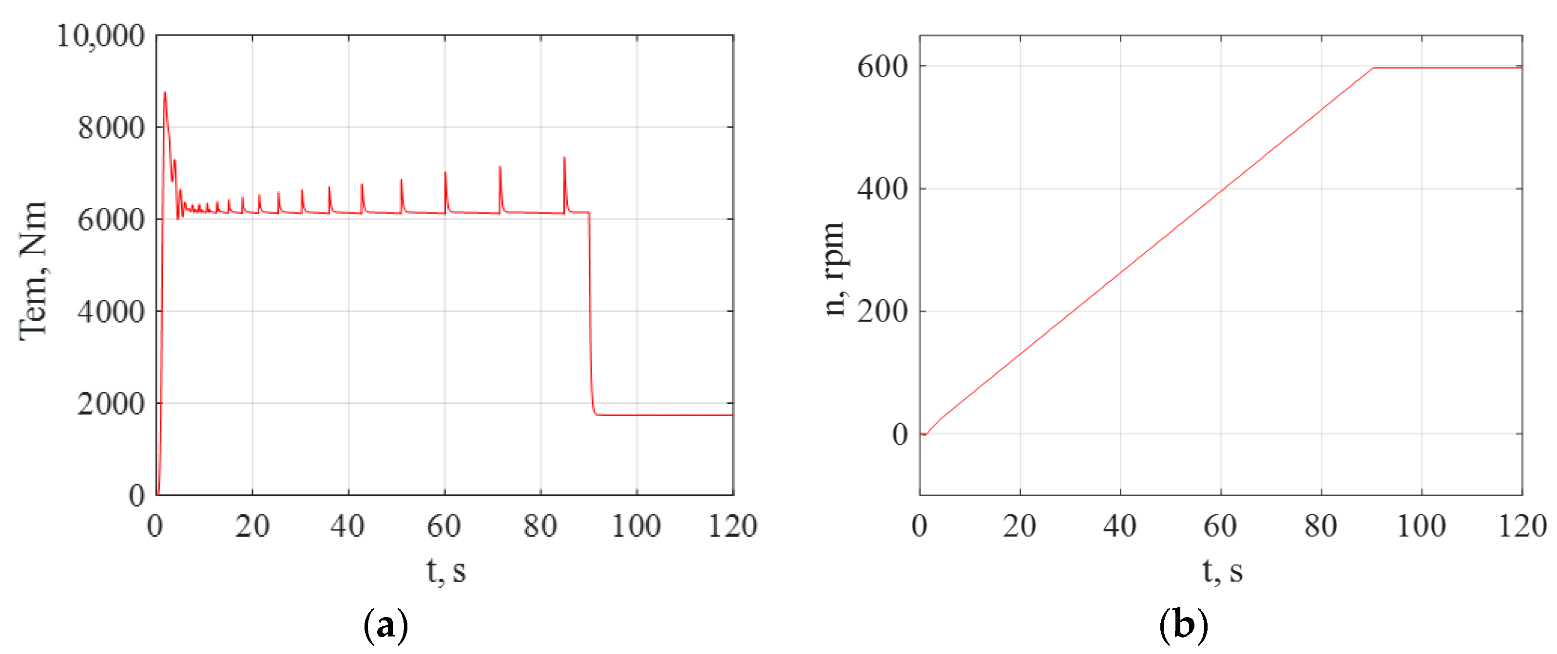
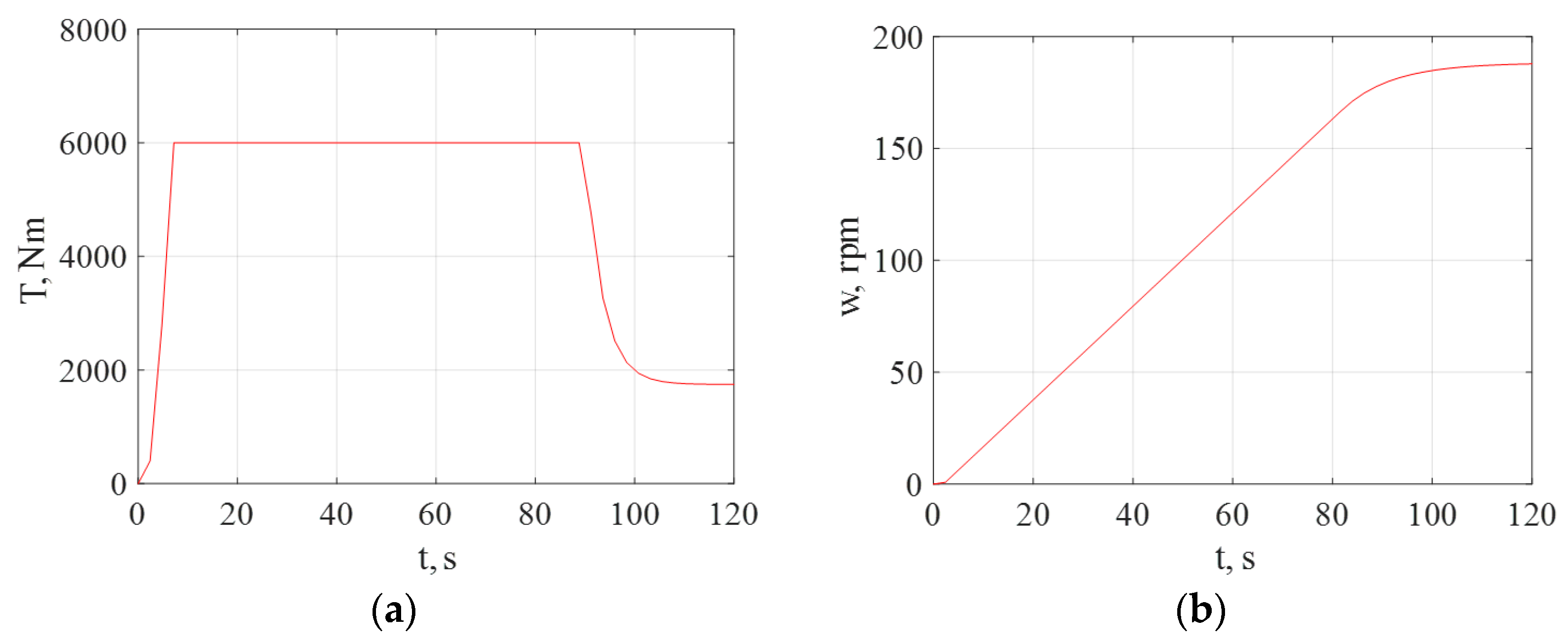
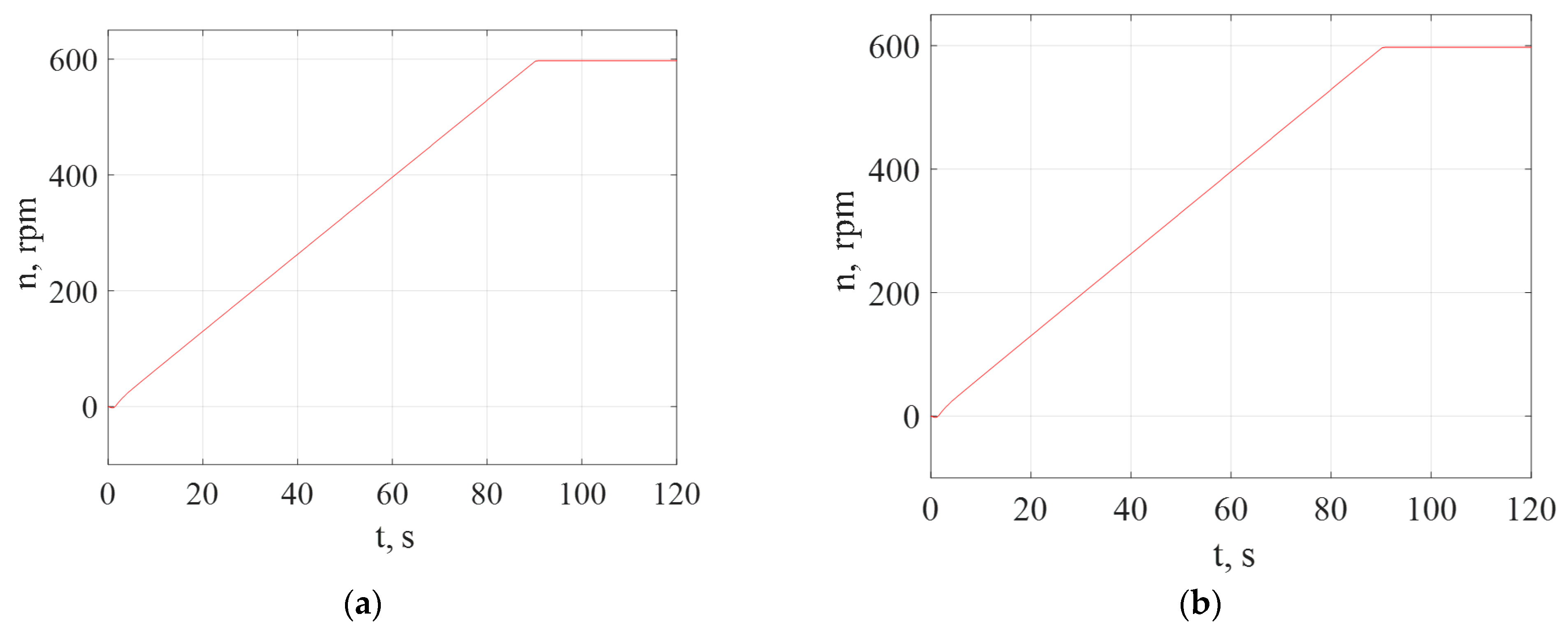
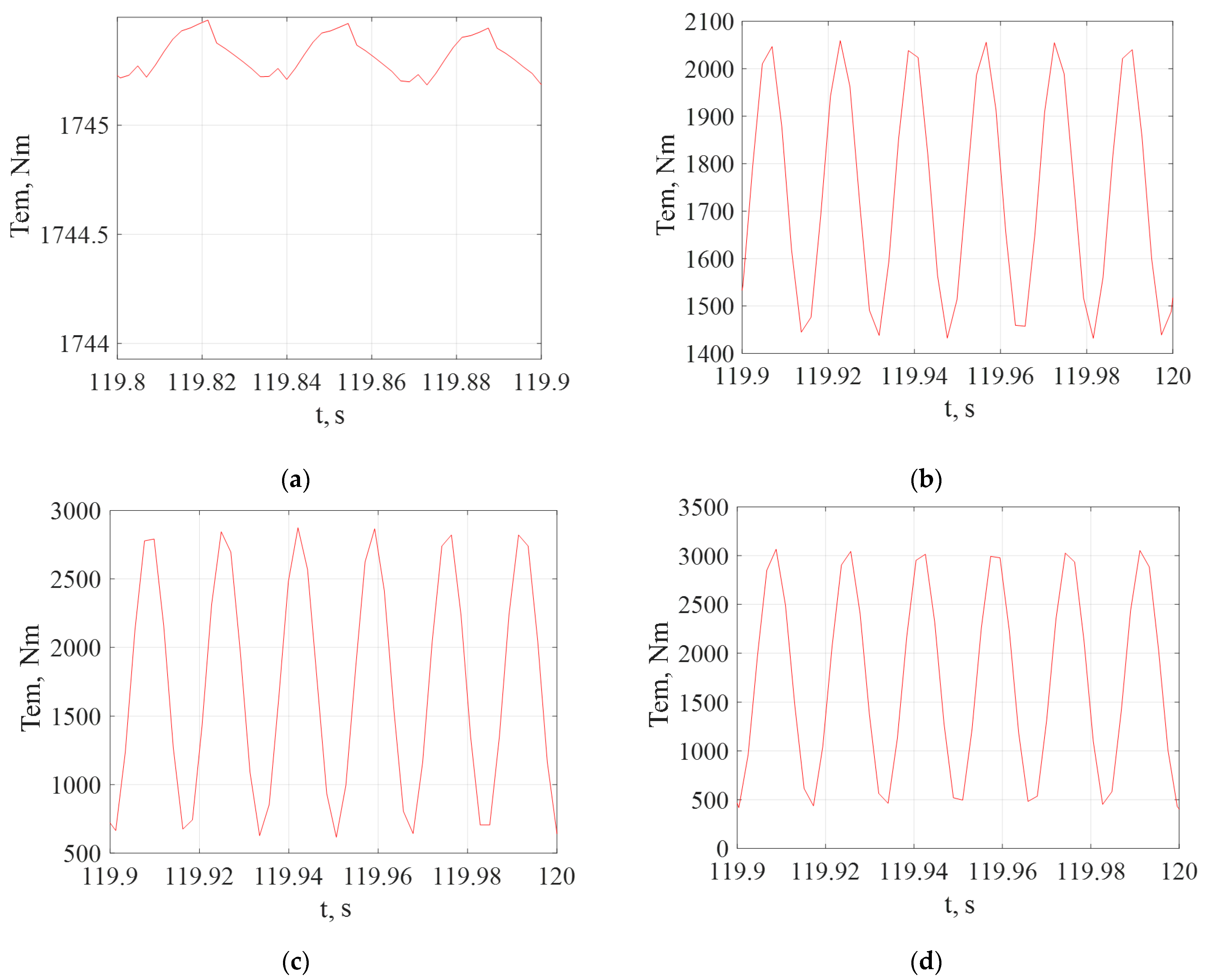
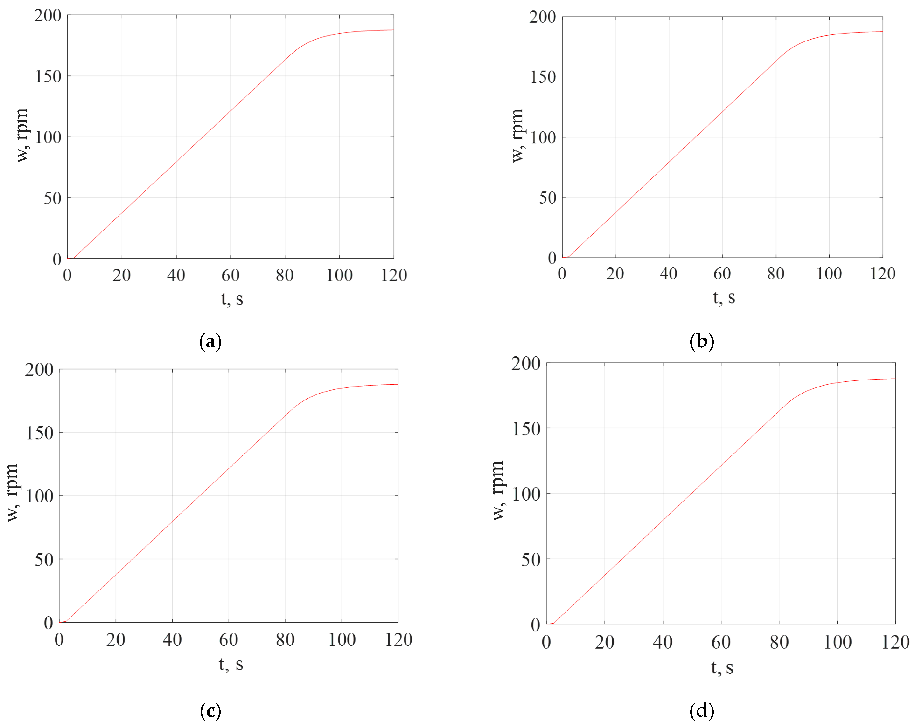
Studies of traction drive control systems in emergency modes were carried out after the end of transient processes in the traction engine. To determine the time of transient processes for the scalar and vector control systems, the starting characteristics of the simulation model were obtained in the normal operating mode of the drive. The diagrams of the torque and rotation frequency of the traction motor for the scalar control system are shown in Figure 3a,b, respectively. Diagrams of the torque and rotation frequency of the traction motor shaft for the vector control system are shown in Figure 4a,b, respectively.
According to the starting diagrams for scalar (Figure 3) and vector (Figure 4) control systems, the times of transient processes are determined. For a scalar control system, it was 90 s, for a vector—100 s; therefore, all further studies were carried out for a time greater than 100 s. According to the starting diagrams for scalar (Figure 3) and vector (Figure 4) control systems, the times of transient processes are determined. For a scalar control system, it was 90 s, for a vector—100 s; therefore, all further studies were carried out for a time greater than 100 s.
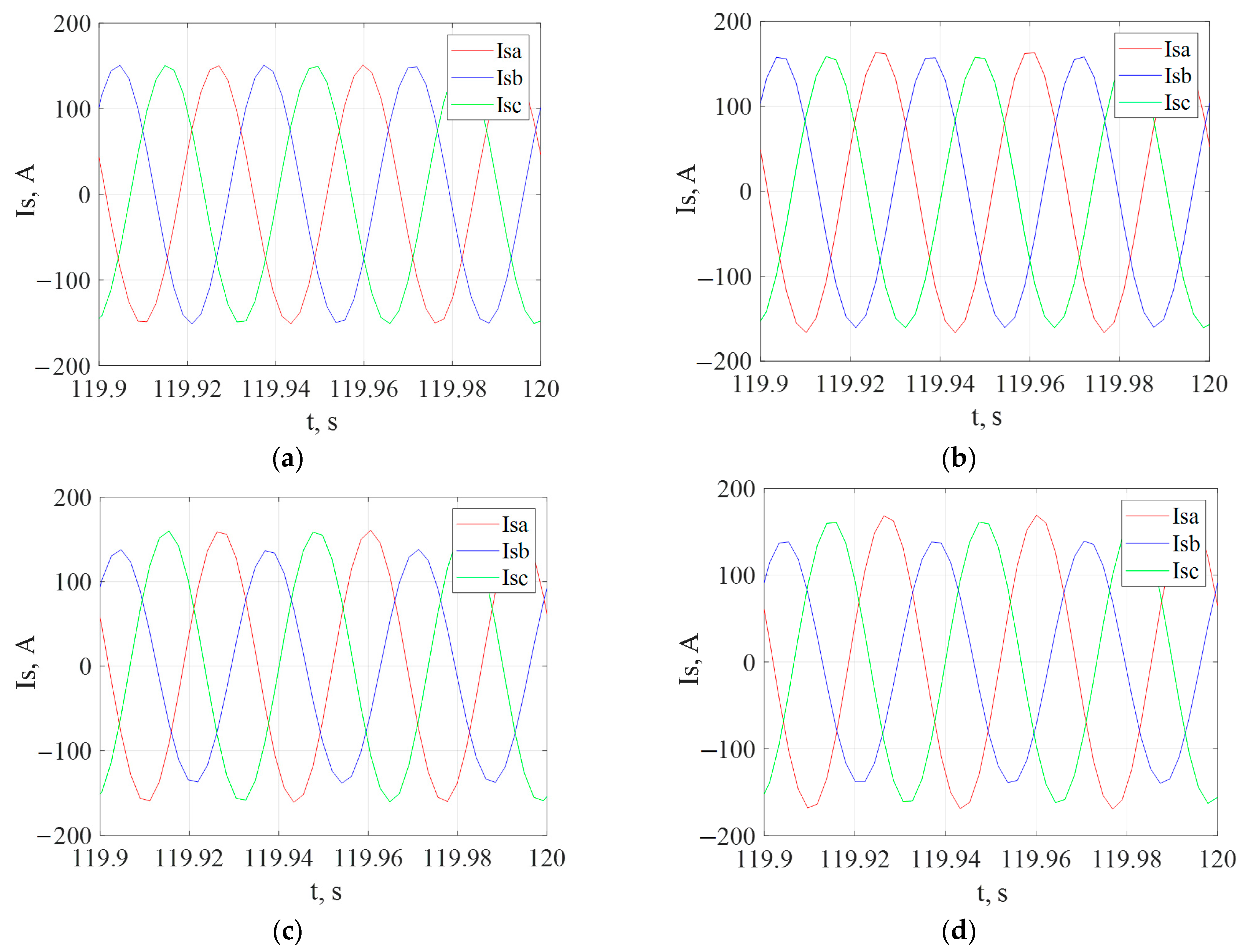
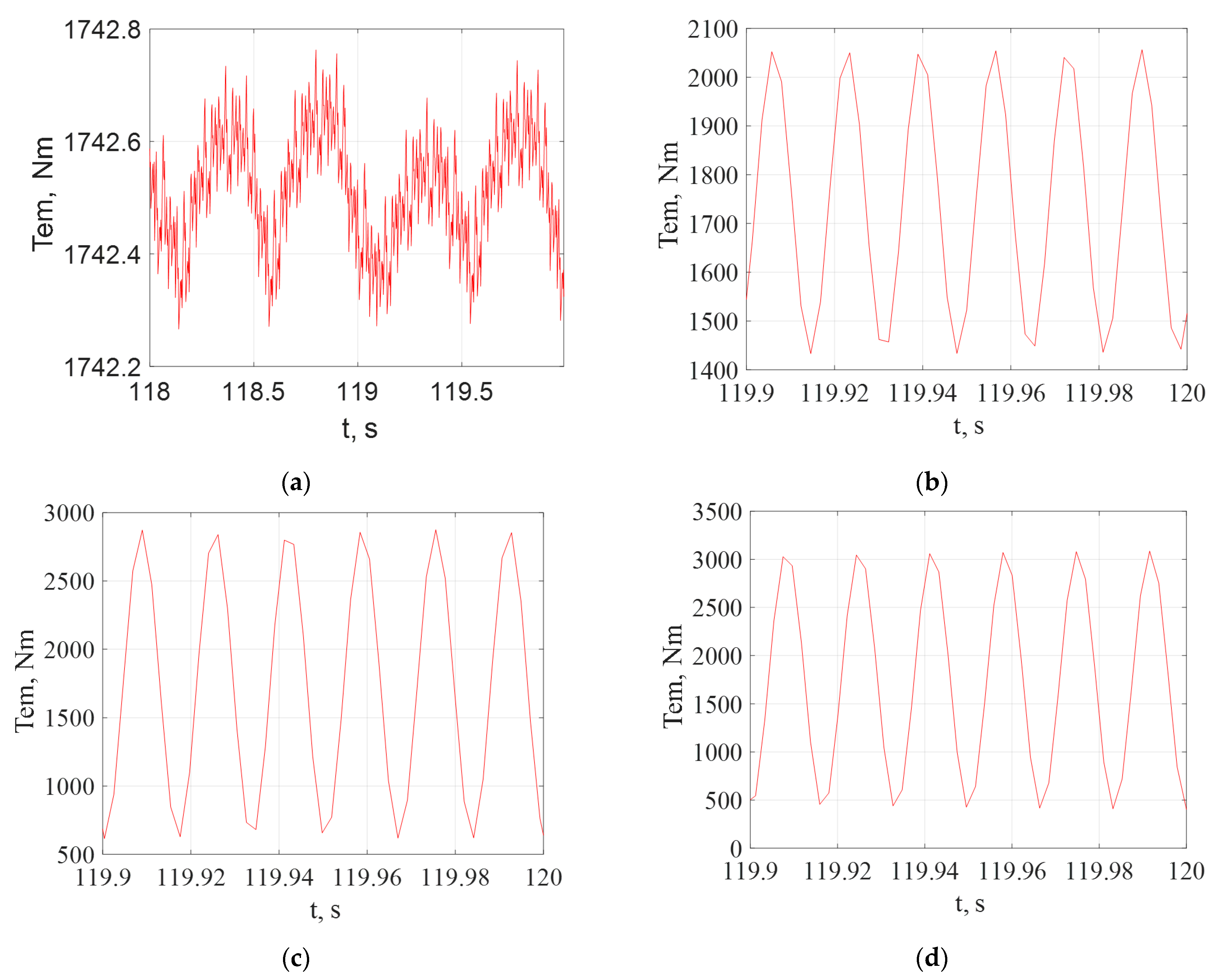
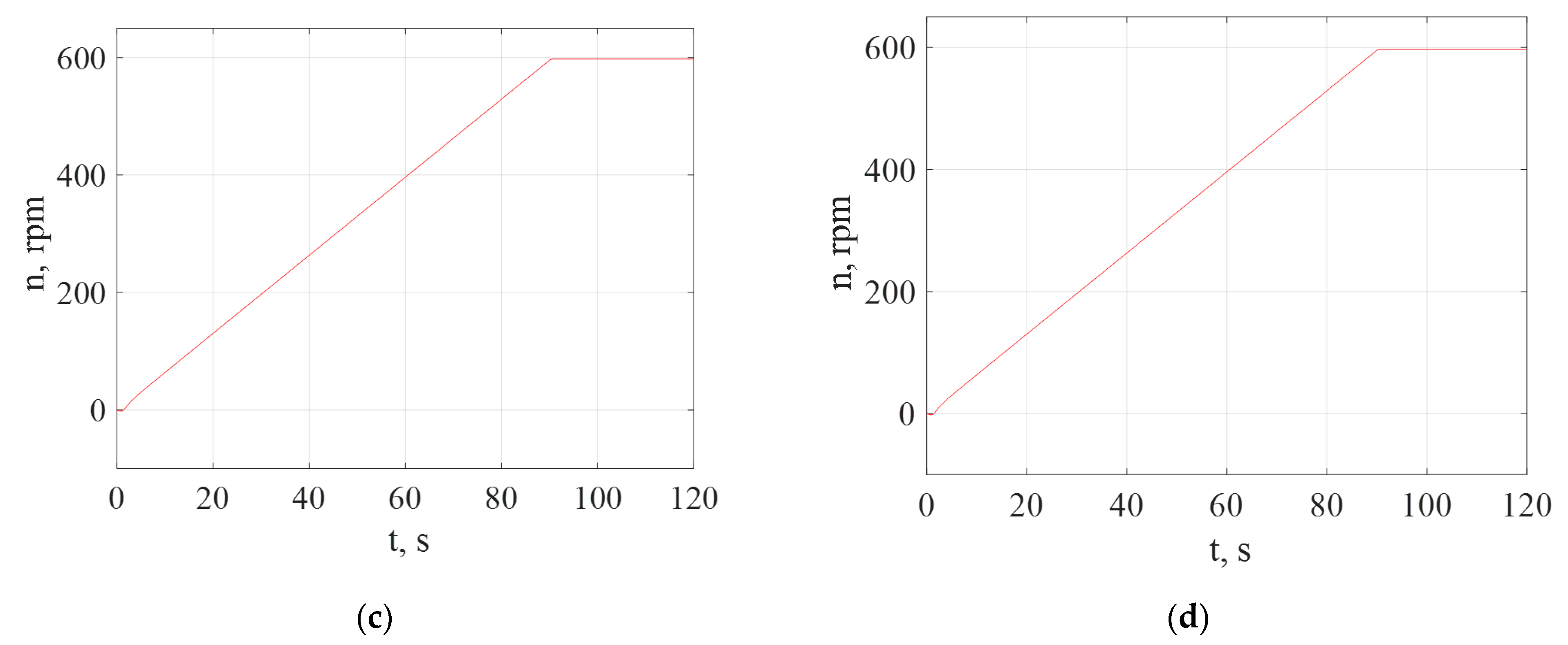
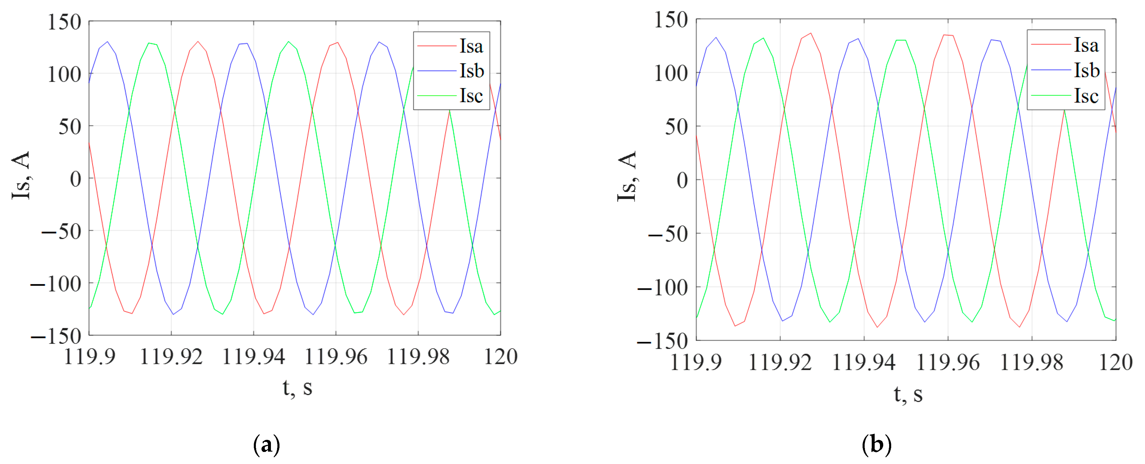
The purpose of the first experiment was to record the starting characteristics of the current (Figure 5a), torque (Figure 6a) and rotation frequency (Figure 7a) for the normal operation of a traction drive with a scalar control system.
The second experiment consisted in taking the starting characteristics of the current with a 10% damage to the stator winding of phase A (Figure 5b), torque (Figure 6b) and rotation frequency (Figure 7b) for normal operation of the drive. The imitation of the damaged stator windings was carried out according to the method described in [31]. An analysis of the results given in [36] shows that with an interturn closure of 5% of the windings, the effect of the asymmetry of the stator windings on the starting characteristics is insignificant. Turn-to-turn closure of 10% of the stator windings and more has a significant effect on the starting characteristics of the traction motor.
The third experiment consisted in taking the starting characteristics of the current when the supply voltage of phase B deviates by 2% from the nominal value (Figure 5c), torque (Figure 6c), and rotation frequency (Figure 7c) for the normal operation of the drive.
As shown in the study [37], the asymmetry of the supply voltage system has a much greater effect on the coefficient of unbalance of the phase currents of an induction motor than the turn-to-turn circuit.
Therefore, when modeling the asymmetry of the supply voltages of the traction motor, the degree of this asymmetry was chosen to be less than the degree of asymmetry of the resistances of the stator windings of the motor.
The fourth experiment consisted in the removal of the starting characteristics of the current with a 10% damage to the stator winding of phase A and a deviation of the supply voltage of phase B by 2% from the nominal value (Figure 5d), torque (Figure 6d), and rotation frequency (Figure 7d) for the normal operation of the drive.
The measurement results are listed in Table 4.
The torque ripple factor is determined by the expression [35]
kpT = (Tmax − Tmin)·100/2·Tmid,
Asymmetry factor of stator phase currents [35]
knbI = (Ismax − Ismin)·100/Imid,
The calculation results are listed in Table 4.
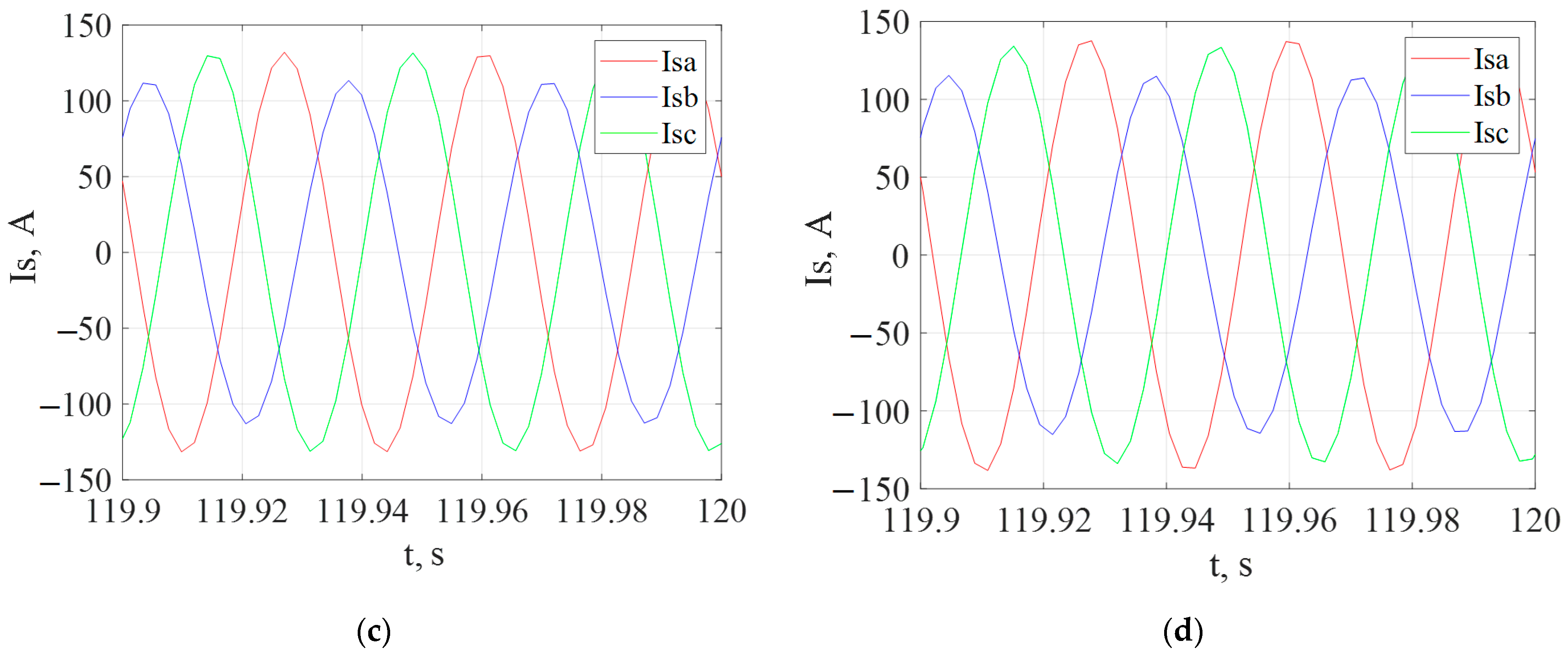
The fifth experiment consisted of the removal of the starting characteristics of the current with vector control (Figure 8a), torque (Figure 9a), and rotation frequency (Figure 10a) for normal operation of the drive.
The sixth experiment consisted in taking the starting characteristics of the current with vector control with 10% damage to the stator winding of phase A (Figure 8b), torque (Figure 9b), and rotation frequency (Figure 10b) for normal operation of the drive.
The seventh experiment consisted in the removal of the starting characteristics of the current with vector control when the supply voltage of phase B deviates by 2% from the nominal value (Figure 8c), the torque (Figure 9c), and rotation frequency (Figure 10c) for the nominal drive operation.
The eighth experiment consisted in the removal of the starting characteristics of the current with vector control with a 10% damage to the stator winding of phase A and a deviation of the supply voltage of phase B by 2% from the nominal value (Figure 8d), torque (Figure 9d), and rotation frequency (Figure 10d) for normal operation of the drive.
The measurement results are listed in Table 5.
The torque ripple coefficient and the stator phase current unbalance coefficient are determined in accordance with expressions (22) and (23), respectively. The calculation results are listed in Table 5.
4. Discussion
The authors did not develop structural diagrams of scalar or vector control systems. The authors referred to previously published work by other researchers [34,35]. The authors did not investigate the variable modes of electric locomotive movement, as this would greatly increase the volume of the article.
The simulation accuracy of the scalar and vector control systems can be estimated by comparing the obtained values of the engine speed and torque. The rotational speed was determined without error. The error in determining the torque for both scalar and vector control systems was no more than 0.1%.
Thus, simulation models of traction induction motor control can be considered reliable.
The analysis of starting diagrams of stator currents and torque gave the following results:
- -
- The asymmetry in the power supply system has a greater effect on the torque ripple and the imbalance of the stator phase currents than the asymmetry of the stator windings. With a deviation of the phase voltage of one of their phases by 2%, the torque ripple coefficient for a scalar control system was 40%, the unbalance coefficient of the stator phase currents was 14%. With a vector control scheme, the torque ripple coefficient was 34.5%, and the unbalance coefficient of the stator phase currents was 17%. With a deviation of the impedance of one of the phases by 10%, similar parameters for scalar control were: torque ripple coefficient—18%, stator phase current imbalance coefficient—4.5%. With vector control: torque ripple factor—15, 5%, unbalance factor of stator phase currents—1.5%.
- -
- With the same damages with a vector control scheme, less ripple of the torque occurs, and with a scalar one, a smaller imbalance of phase currents.
However, it should be borne in mind that the models of control schemes were based on the assumption that the operation of the inverter has little effect on the ripple of the motor torque. This factor imposes some restrictions on the use of the developed models. To take this factor into account, additional research should be carried out. At the same time, the authors understand the difficulties with obtaining experimental data in the operating conditions of an electric locomotive.
In the process of working on this article, the authors encountered objective difficulties associated with the impossibility of conducting a full-scale experiment and thus obtaining reliable experimental data. This is due to the fact that when conditions are created in operation for the turn-to-turn closure of the traction motor windings, it completely breaks down and requires major repairs.
An attempt to optimize the traction drive control system to increase the energy efficiency of the traction drive can be a continuation of the research.
5. Conclusions
1. A mathematical model of an asynchronous traction drive has been built to study the operation of a motor with asymmetric characteristics of windings and asymmetry of power parameters.
2. The modeling of the control system of the output converter of the asynchronous traction motor with scalar and vector control has been carried out.
3. Starting characteristics for scalar and vector control systems have been received. In addition, the simulation results showed that the duration of transient processes in the traction drive with a vector control system is longer than with a scalar system.
This is due to the fact that with a vector control system, the flux linkage and speed control channels are separated in time. The flux link control channel performs the task first, and then the speed control channel. The separation of the control channels in time leads to the fact that with a vector control system, when starting the traction motor, there are no torque pulsations. With a scalar control system, these pulsations exist since control is carried out through only one channel—torque.
4. The starting characteristics of the traction motor for scalar and vector control systems were obtained for symmetric and asymmetric operating modes. The following asymmetric modes of operation are considered: asymmetry in the traction motor; asymmetry in the output converter; asymmetry in the traction motor and the output converter at the same time. The asymmetry in the motor was modeled by reducing the stator winding impedance by 10% of the nominal value. The asymmetry of the power supply system was obtained by reducing the phase voltage of one of the phases by 2%.
5. Comparison of the obtained starting characteristics gave the following results:
- -
- With an asymmetry of the power supply system, the ripple coefficient of the motor torque is 2.3 times greater than with the asymmetry of the stator windings with scalar control and 2.2 times more with vector control; the current imbalance coefficient is 3 times higher with scalar control and 11 times higher with vector control.
- -
- With the same damages with a vector control scheme, less ripple of the torque occurs, and with a scalar one, a smaller imbalance of phase currents.
6. Patents
The implementation of this study became possible thanks to the funding by the Ministry of Education and Science of Ukraine of the research project “Improving the energy efficiency of railway rolling stock based on resource-saving technologies and smart energy systems” (state registration number 0120U101912).
Author Contributions
Conceptualization, S.G. and V.T.; methodology, S.S. and P.Š.; software, B.L.; validation, S.G., S.S. and B.L.; formal analysis, P.Š.; investigation, S.G. and B.L.; resources, S.S., P.Š. and B.L.; writing—original draft preparation, S.S. and B.L.; writing—review and editing, S.G. and V.T.; visualization, B.L. and P.Š.; supervision, S.G. and V.T. All authors have read and agreed to the published version of the manuscript.
Funding
This publication was realized with the support of Operational Program Integrated Infrastructure 2014–2020 of the project: Innovative Solutions for Propulsion, Power and Safety Components of Transport Vehicles, code ITMS 313011V334, co-financed by the European Regional Development Fund.
Institutional Review Board Statement
Not applicable.
Informed Consent Statement
Not applicable.
Data Availability Statement
Not applicable.
Conflicts of Interest
The authors declare no conflict of interest.
References
- Mikhailov, E.; Semenov, S.; Dižo, J.; Kravchenko, K. Research of Possibilities of Reducing the Driving Resistance of a Railway Vehicle by Means of the Wheel Construction Improvement. Transp. Res. Procedia 2019, 40, 831–838. [Google Scholar] [CrossRef]
- Tkachenko, V.; Sapronova, S.; Zub, E.; Morneva, M. Closed Power Loops in the Guidance of Vehicles by Railway Track System. In Transport Means—Proceedings of the International Conference, Online Conference, 30 September–2 October 2020; Kaunas University of Technology: Kaunas, Lithuania, 2020; pp. 554–559. Available online: https://transportmeans.ktu.edu/wp-content/uploads/sites/307/2018/02/Transport-means-A4-II-dalis.pdf (accessed on 3 January 2022).
- Hauser, V.; Nozhenko, O.S.; Kravchenko, K.O.; Loulová, M.; Gerlici, J.; Lack, T. Innovative Wheel Tread Design Aimed to Tramcar-Track Interaction Improvement When Passing Curves of a Small Radius. MATEC Web of Conferences. EDP Sci. 2018, 157, 03010. [Google Scholar] [CrossRef]
- Gorbunov, M.; Gerlici, J.; Kara, S.; Nozhenko, O.; Chernyak, G.; Kravchenko, K.; Lack, T. New Principle Schemes of Freight Cars Bogies. Manuf. Technol. 2018, 18, 233–238. [Google Scholar] [CrossRef]
- Gerlici, J.; Gorbunov, M.; Nozhenko, O.; Pistek, V.; Lack, T.; Kravchenko, K. About Creation of Bogie of the Freight Car. Commun.—Sci. Lett. Univ. Zilina 2017, 19, 29–35. Available online: http://komunikacie.uniza.sk/index.php/communications/article/view/208 (accessed on 3 January 2022).
- Hauser, V.; Nozhenko, O.S.; Kravchenko, K.O.; Loulová, M.; Gerlici, J.; Lack, T. Proposal of a Mechanism for Setting Bogie Wheelsets to Radial Position While Riding along Track Curve. Manuf. Technol. 2017, 17, 186–192. [Google Scholar] [CrossRef]
- Mikhailov, E.; Sapronova, S.; Tkachenko, V.; Semenov, S.; Smyrnova, I.; Kholostenko, Y. Improved Solution of Guiding of Railway Vehicle in Curves. In Transport Means—Proceedings of the 23rd International Scientific Conference TRANSPORT MEANS 2019, Palanga, Lithuania, 2–4 October 2019; Printing House “Technologija”: Kaunas, Lithuania, 2019; pp. 916–921. ISSN1 1822-296 X. ISSN2 2351-7034. Available online: https://transportmeans.ktu.edu/wp-content/uploads/sites/307/2018/02/Transport-means-2019-Part-2.pdf (accessed on 3 January 2022).
- Ronanki, D.; Singh, S.A.; Williamson, S.S. Comprehensive Topological Overview of Rolling Stock Architectures and Recent Trends in Electric Railway Traction Systems. IEEE Trans. Transp. Electr. 2017, 3, 724–738. [Google Scholar] [CrossRef]
- Titova, T.S.; Evstaf’ev, A.M.; Nikitin, V.V. The Use of Energy Storages to Increase the Energy Effectiveness of Traction Rolling Stock. Russ. Electr. Eng. 2018, 89, 576–580. [Google Scholar] [CrossRef]
- Huang, X.; Liao, Q.; Li, Q.; Tang, S.; Sun, K. Power Management in Co-Phase Traction Power Supply System with Super Capacitor Energy Storage for Electrified Railways. Railw. Eng. Sci. 2020, 28, 85–96. [Google Scholar] [CrossRef] [Green Version]
- Petrenko, O.; Liubarskiy, B.; Pliugin, V. Determination of Railway Rolling Stock Optimal Movement Modes. Electr. Eng. Electromech. 2017, 6, 27–31. [Google Scholar] [CrossRef] [Green Version]
- Goolak, S.; Tkachenko, V.; Bureika, G.; Vaičiūnas, G. Method of Spectral Analysis of Traction Current of AC Electric Locomotives. Transport 2020, 35, 658–668. [Google Scholar] [CrossRef]
- Sokol, Y.; Zamaruiev, V.; Ivakhno, V.; Styslo, B. Improving the Quality of Electrical Energy in the Railway Power Supply System. In Proceedings of the 2018 IEEE 38th International Conference on Electronics and Nanotechnology (ELNANO), Kyiv, Ukraine, 24–26 April 2018; IEEE: New York, NY, USA, 2018; pp. 563–566. [Google Scholar] [CrossRef]
- Nezevak, V.; Shatokhin, A. Interaction’s Simulation Modeling of Electric Rolling Stock and Electric Traction System. In Proceedings of the 2019 International Ural Conference on Electrical Power Engineering (UralCon), Chelyabinsk, Russia, 1–3 October 2019; IEEE: New York, NY, USA, 2019; pp. 410–416. [Google Scholar] [CrossRef]
- Goolak, S.; Sapronova, S.; Tkachenko, V.; Riabov, I.; Batrak, Y. Improvement of the Model of Power Losses in the Pulsed Current Traction Motor in an Electric Locomotive. East.-Eur. J. Enterp. Technol. 2020, 6, 38–46. [Google Scholar] [CrossRef]
- Pugachev, A. Efficiency Increasing of Induction Motor Scalar Control Systems. In Proceedings of the 2017 International Conference on Industrial Engineering, Applications and Manufacturing (ICIEAM), Chelyabinsk, Russia, 16–19 May 2017; pp. 1–5. [Google Scholar] [CrossRef]
- Costa, C.A.; Nied, A.; Nogueira, F.G.; Turqueti, M.D.A.; Rossa, A.J.; Dezuo, T.J.M.; Junior, W.B. Robust LPV Scalar Control Applied in High Performance Induction Motor Drives. IEEE Trans. Ind. Electr. 2020, 68, 10558–10568. [Google Scholar] [CrossRef]
- Kumar, Y.S.; Poddar, G. Medium-Voltage Vector Control Induction Motor Drive at Zero Frequency Using Modular Multilevel Converter. IEEE Trans. Ind. Electr. 2017, 65, 125–132. [Google Scholar] [CrossRef]
- Hassan, M.M.; Shaikh, M.S.; Jadoon, H.U.K.; Atif, M.R.; Sardar, M.U. Dynamic Modeling and Vector Control of AC Induction Traction Motor in China Railway. Sukkur IBA J. Emerg. Technol. 2020, 3, 115–125. [Google Scholar] [CrossRef]
- Wang, H.; Liu, Y.C.; Ge, X. Sliding-Mode Observer-Based Speed-Sensorless Vector Control of Linear Induction Motor with a Parallel Secondary Resistance Online Identification. IET Electr. Power Appl. 2018, 12, 1215–1224. [Google Scholar] [CrossRef]
- Lee, J.K.; Kim, J.W.; Park, B.G. Fast Anti-Slip Traction Control for Electric Vehicles Based on Direct Torque Control with Load Torque Observer of Traction Motor. In Proceedings of the 2021 IEEE Transportation Electrification Conference & Expo (ITEC), Chicago, IL, USA, 23–25 June 2021; IEEE: New York, NY, USA, 2021; pp. 321–326. [Google Scholar] [CrossRef]
- Aissa, B.; Hamza, T.; Yacine, G.; Mohamed, N. Impact of Sensorless Neural Direct Torque Control in a Fuel Cell Traction System. Int. J. Electr. Comput. Eng. (IJECE) 2021, 11, 2725–2732. [Google Scholar] [CrossRef]
- Karlovsky, P.; Lettl, J. Induction Motor Drive Direct Torque Control and Predictive Torque Control Comparison Based on Switching Pattern Analysis. Energies 2018, 11, 1793. [Google Scholar] [CrossRef] [Green Version]
- Busher, V.; Chornyi, O.; Glazeva, O.; Kuznetsov, V.G.; Tytiuk, V.; Tryputen, M. Optimal Control Method of High-Voltage Frequency Converters with Damaged Cells. IOP Conf. Ser. Mater. Sci. Eng. 2020, 985, 012021. [Google Scholar] [CrossRef]
- Tuychieva, M. Control of Electric Locomotives with Asynchronous Electric Motors under Asymmetric Operating Conditions in Uzbekistan. IOP Conf. Ser. Earth Environ. Sci. 2020, 614, 012060. [Google Scholar] [CrossRef]
- Dong, H.; Chen, F.; Wang, Z.; Jia, L.; Qin, Y.; Man, J. An Adaptive Multisensor Fault Diagnosis Method for High-Speed Train Traction Converters. IEEE Trans. Power Electr. 2020, 36, 6288–6302. [Google Scholar] [CrossRef]
- Zagirnyak, M.; Kalinov, A.; Melnykov, V. Variable-Frequency Electric Drive with a Function of Compensation for Induction Motor Asymmetry. In Proceedings of the 2017 IEEE First Ukraine Conference on Electrical and Computer Engineering (UKRCON), Kyiv, Ukraine, 29 May–2 June 2017; IEEE: New York, NY, USA, 2017; pp. 338–344. [Google Scholar] [CrossRef]
- Zagirnyak, M.; Kalinov, A.; Melnykov, V. Decrease of the Thermal Overloads of a Variable-Frequency Electric Drive at Damages in the Electric Circuit of an Induction Motor Stator. Prz. Elektrotech. 2019, 95, 43–46. [Google Scholar] [CrossRef]
- Melnykov, V. The Correction of the Operation Modes for Frequency-Controlled Induction Motor with Scalar Control under Stator Windings Damage Appearance. In Proceedings of the 2021 IEEE International Conference on Modern Electrical and Energy Systems (MEES), Kremenchuk, Ukraine, 21–24 September 2021; IEEE: New York, NY, USA, 2021; pp. 1–6. [Google Scholar] [CrossRef]
- Rules of Traction Calculations for Train Work on Electric Locomotives ChS7, ChS8, DE1, DS3, 2EL5, 2ES5K, Diesel Locomotives TEP150, TEM103, Diesel Trains DEL-02, Electric Trains EPL2t, EPL9t.2010 (Ukrainian), Ukrzaliznytsia. 2010. Available online: http://scbist.com/scb/uploaded/1_1599018086.pdf. (accessed on 3 January 2022).
- Goolak, S.; Liubarskyi, B.; Sapronova, S.; Tkachenko, V.; Riabov, I.; Glebova, M. Improving a Model of the Induction Traction Motor Operation Involving Non-Symmetric Stator Windings. East.-Eur. J. Enterp. Technol. 2021, 4, 45–58. [Google Scholar] [CrossRef]
- Goolak, S.; Gerlici, J.; Tkachenko, V.; Sapronova, S.; Lack, T.; Kravchenko, K. Determination of Parameters of Asynchronous Electric Machines with Asymmetrical Windings of Electric Locomotives. Commun.—Sci. Lett. Univ. Zilina 2019, 21, 24–31. [Google Scholar] [CrossRef]
- Spiryagin, M.; Vollebregt, E.; Hayman, M.; Persson, I.; Wu, Q.; Bosomworth, C.; Cole, C. Development and Computational Performance Improvement of the Wheel-Rail Coupling for Heavy Haul Locomotive Traction Studies. Veh. Syst. Dyn. 2020, 1–28. [Google Scholar] [CrossRef]
- Gouichiche, A.; Safa, A.; Chibani, A.; Tadjine, M. Global Fault-Tolerant Control Approach for Vector Control of an Induction Motor. Int. Trans. Electr. Energy Syst. 2020, 30, 12440. [Google Scholar] [CrossRef]
- Che, H.; Wu, B.; Yang, J.; Tian, Y. Speed Sensorless Sliding Mode Control of Induction Motor Based on Genetic Algorithm Optimization. Meas. Control 2020, 53, 192–204. [Google Scholar] [CrossRef] [Green Version]
- Goolak, S.; Gerlici, J.; Gubarevych, O.; Lack, T.; Pustovetov, M. Imitation Modeling of an Inter-Turn Short Circuit of an Asynchronous Motor Stator Winding for Diagnostics of Auxiliary Electric Drives of Transport Infrastructure. Commun.—Sci. Lett. Univ. Zilina 2021, 23, C65–C74. [Google Scholar] [CrossRef]
- Petko, V.; Petrov, A.; Rakhimzhanova, I.; Shakhov, V.; Ushakov, Y.; Fomin, M. Permissible Voltage Asymmetry for Asynchronous Motor Operating in Non-Nominal Operating Conditions. In Proceedings 19th International Scientific Conference “Engineering for Rural Development”; Latvia University of Life Sciences and Technologies: Jelgava, Latvia, 2020; Volume 19, pp. 897–905. [Google Scholar] [CrossRef]
Figure 1.
Block diagram of scalar control of an asynchronous motor.

Figure 2.
Block diagram of asynchronous motor vector control (*value expressed in relative units).

Figure 3.
Starting characteristics of the traction motor for scalar control: (a) torque diagram; (b) diagram rotation frequency of the traction motor.
Figure 3.
Starting characteristics of the traction motor for scalar control: (a) torque diagram; (b) diagram rotation frequency of the traction motor.

Figure 4.
Starting characteristics of the traction motor for vector control: (a) torque diagram; (b) diagram rotation frequency of the traction motor.
Figure 4.
Starting characteristics of the traction motor for vector control: (a) torque diagram; (b) diagram rotation frequency of the traction motor.

Figure 5.
Starting characteristics of the stator current of a traction motor under scalar control: (a) when the motor is operating in normal mode; (b) if the stator phase A winding is damaged; (c) in the presence of asymmetry in phase B of the power supply system; (d) in case of damage to the stator phase A winding and the presence of asymmetry in phase B of the power supply system at the same time.

Figure 6.
Starting characteristics of the stator torque of a traction motor under scalar control: (a) when the motor is operating in normal mode; (b) if the stator phase A winding is damaged; (c) in the presence of asymmetry in phase B of the power supply system; (d) in case of damage to the stator phase A winding and the presence of asymmetry in phase B of the power system at the same time.

Figure 7.
Starting characteristics of the rotation frequency of the traction motor under scalar control: (a) when the motor is operating in normal mode; (b) if the stator phase A winding is damaged; (c) in the presence of asymmetry in phase B of the power supply system; (d) in case of damage to the stator phase A winding and the presence of asymmetry in phase B of the power supply system at the same time.


Figure 8.
Starting characteristics of the stator current of a traction motor with vector control: (a) when the motor is operating in normal mode; (b) if the stator phase A winding is damaged; (c) in the presence of asymmetry in phase B of the power supply system; (d) in case of damage to the stator phase A winding and the presence of asymmetry in phase B of the power supply system at the same time.


Figure 9.
Starting characteristics of the stator torque of a traction motor with vector control: (a) when the motor is operating in normal mode; (b) if the stator phase A winding is damaged; (c) in the presence of asymmetry in phase B of the power supply system; (d) in case of damage to the stator phase A winding and the presence of asymmetry in phase B of the power system at the same time.

Figure 10.
Starting characteristics of the rotation frequency of the traction motor under vector control: (a) when the motor is operating in normal mode; (b) if the stator phase A winding is damaged; (c) in the presence of asymmetry in phase B of the power supply system; (d) in case of damage to the stator phase A winding and the presence of asymmetry in phase B of the power supply system at the same time.


Table 1.
Technical characteristics of the electric locomotive DS-3.
| Indicators | Value |
|---|---|
| Number of locomotive axles N, pcs. | 4 |
| Starting traction FT, N | 27,523 |
| Restrictions | By current |
| Traction motor type | AD914U1 |
| Electric locomotive weight m, kg | 90,000 |
| Wheel radius R, m | 0.6 |
| Gear ratio μ, p.u | 4.105 |
| Gearbox efficiency ηr,% | 96 |
Table 2.
Traction motor parameters AD914U1.
| Indicators | Value |
|---|---|
| Power P, kW | 1200 |
| Current value of line voltage Unom, V | 1870 |
| Effective value Inom, A | 450 |
| Rated frequency of the supply voltage f, Hz | 55.8 |
| Number of phases n, pcs. | 3 |
| Number of pole pairs pp | 3 |
| Nominal rotation frequency nr, rpm | 1110 |
| Efficiency η, % | 95.5 |
| Power factor cosφ, per unit | 0.88 |
| Active resistance of the stator winding rs, Ω | 0.0226 |
| The active resistance of the rotor winding reduced to the stator winding r’r, Ohm | 0.0261 |
| Stator winding leakage inductance Lσs, Hn | 0.00065 |
| Reduced to the stator winding leakage inductance of the rotor winding, L’σr, Hn | 0.00045 |
| Total inductance of the magnetizing circuit Lμ | 0.0194336 |
| Motor moment of inertia J, kg·m2 | 73 |
Table 3.
The results of calculating the basic values and parameters of the regulator.
| Base Values | ||
|---|---|---|
| Base value for voltages, V | Ub = √2·Unom | 1527 |
| Basic value for currents, A | Ιb = √2·Ιnom | 450 |
| Base value for corner frequencies, 1/s | Ωb = 2·π·fnom | 349.345 |
| Base value for electrical angles, rad | θb = 2·π | 6.283 |
| Basic value for resistances, Ohm | Ib = Ub/Inom | 3.393 |
| Base value for flux linkages, Wb | ψb = Ub/Ωb | 4.371 |
| Base value for inductances, H | Lb = ψb/Inom | 0.009713 |
| Base value for powers, W | Pb = 2·Ub·Inom/3 | 1,030,725 |
| Basic value for mechanical angular velocities, 1/s | Ωbmech = Ωb/ppole | 116.448 |
| Basic value for moments, N⋅m | Mb = Pb/Ωbmech | 8851 |
| Base value for time | Tb = 1/Ωb | 0.002862 |
| Basic value for moments of inertia, kg⋅m2 | Tb = Mb·ppole/(Ωb)2 | 0.218 |
| Additional parameters of AM in p.u. | ||
| Magnetizing inductance | L*m = Lm/Lb | 1.334 |
| Magnetizing inductance | L*s = Ls/Lb | 1.401 |
| Rotor phase total inductance | L*r = Lr/Lb | 1.38 |
| R*s = Rs/Rb | 0.00666 | |
| R’*r = R’r/Rb | 0.07692 | |
| Rotor moment of inertia | J*en = Jen/Jb | 335.507 |
| Additional dimensionless parameters of AD | ||
| Total dissipation coefficient | σ = 1 − (L*m)2/(L*s·L*r) | 0.08 |
| Dimensionless stator time constant | χ*s = L*s/R*s | 210.314 |
| Dimensionless rotor time constant | χ*r = L*r/R*r | 179.434 |
| Controller parameters | ||
| Current loop tuning factor X | aIx | 2 |
| Current loop tuning factor Y | aIy | 2 |
| Flow loop adjustment factor | aIμ | 2 |
| Speed loop tuning factor | aω | 2 |
| Uncompensated time constant | χ*μ = 10/(6·τPWM) | 0.361 |
| Proportional coefficient of the current regulator X in the absence of an EMF compensation unit | KpIx = (R*s·σ·χ*s)/(aIx·χ*μ) | 0.155 |
| Integral coefficient of the current regulator X in the absence of an EMF compensation unit | KiIx = (R*s + (χ*μ)2/(χ*r·L*r))/(aIx·χ*μ) | 0.019 |
| Proportional coefficient of the current regulator Y | KpIy = (R*s·σ·χ*s)/(aIy·χ*μ) | 0.155 |
| Integral coefficient of the current regulator Y | KiIy = R*s/(aIx·χ*μ) | 0.00922 |
| Proportional coefficient of the rotor magnetizing current regulator | KpIμ = χ*r/(aIx·aIμ·χ*μ) | 124.226 |
| Integral coefficient of the rotor magnetizing current regulator | KiIμ = 1/(aIx·aIμ·χ*μ) | 0.692 |
| Proportional coefficient of the speed controller | Kpω = J*en·kj/(aIy·aω·χ*μ) | 6736 |
| Integral coefficient of the speed controller | Kiω = 0 | 0 |
Table 4.
Results of modeling scalar control of an asynchronous motor.
| Parameter | Parameter Value | |||
|---|---|---|---|---|
| Experiment 1 | Experiment 2 | Experiment 3 | Experiment 4 | |
| Maximum torque, N·m | 1745.5 | 2047 | 2857 | 3060 |
| Minimum torque value, N·m | 1745.25 | 1433 | 618.4 | 425.9 |
| Average torque, N·m | 1745.375 | 1740 | 1403.3 | 1357.05 |
| Ripple frequency, Hz | 60 | 60 | 60 | 60 |
| Stator phase current A, A | 151.1 | 163.6 | 159.1 | 168.4 |
| Stator phase current B, A | 151.1 | 158.4 | 138.2 | 139.2 |
| Stator phase current C, A | 151.1 | 156.5 | 158.9 | 161.2 |
| Engine speed, rpm | 600 | 600 | 600 | 600 |
| Transient end time, s | 90 | 90 | 90 | 90 |
| Torque ripple factor, kpT, % | 0.002 | 17.64 | 40 | 48.5 |
| Unbalance factor of stator phase currents, knbI | 0 | 4.4 | 13.7 | 18.7 |
Table 5.
Results of modeling vector control of an asynchronous motor.
| Parameter | Parameter Value | |||
|---|---|---|---|---|
| Experiment 5 | Experiment 6 | Experiment 7 | Experiment 8 | |
| Maximum torque, N·m | 1744.2 | 2009 | 2942 | 3090 |
| Minimum torque value, N·m | 1743.5 | 1472 | 541.7 | 417.7 |
| Average torque, N·m | 1743.85 | 1740.5 | 1741.85 | 1753.85 |
| Ripple frequency, Hz | 60 | 60 | 60 | 60 |
| Stator phase current A, A | 133 | 138.6 | 141.8 | 146.8 |
| Stator phase current B, A | 133 | 133.1 | 118.9 | 116.9 |
| Stator phase current C, A | 133 | 132.3 | 140.9 | 140.6 |
| Engine speed, rpm | 600 | 597.8 | 597.6 | 597.3 |
| Transient end time, s | 90 | 90.3 | 90.51 | 90.65 |
| Torque ripple factor, kpT, % | 2 | 15.4 | 34.5 | 38.0 |
| Unbalance factor of stator phase currents, knbI | 0 | 1.6 | 17.1 | 22.1 |
Publisher’s Note: MDPI stays neutral with regard to jurisdictional claims in published maps and institutional affiliations. |
© 2022 by the authors. Licensee MDPI, Basel, Switzerland. This article is an open access article distributed under the terms and conditions of the Creative Commons Attribution (CC BY) license (https://creativecommons.org/licenses/by/4.0/).
Share and Cite
MDPI and ACS Style
Goolak, S.; Tkachenko, V.; Šťastniak, P.; Sapronova, S.; Liubarskyi, B. Analysis of Control Methods for the Traction Drive of an Alternating Current Electric Locomotive. Symmetry 2022, 14, 150. https://doi.org/10.3390/sym14010150
AMA Style
Goolak S, Tkachenko V, Šťastniak P, Sapronova S, Liubarskyi B. Analysis of Control Methods for the Traction Drive of an Alternating Current Electric Locomotive. Symmetry. 2022; 14(1):150. https://doi.org/10.3390/sym14010150
Chicago/Turabian StyleGoolak, Sergey, Viktor Tkachenko, Pavol Šťastniak, Svitlana Sapronova, and Borys Liubarskyi. 2022. "Analysis of Control Methods for the Traction Drive of an Alternating Current Electric Locomotive" Symmetry 14, no. 1: 150. https://doi.org/10.3390/sym14010150
Note that from the first issue of 2016, this journal uses article numbers instead of page numbers. See further details here.