Article

Design and Research of Symmetrical Multi-Throttle Thrust Hydrostatic Bearing Based on Comparative Analysis of Various Meshes

1
Center of Ultra-Precision Optoelectronic Instrument Engineering, Harbin Institute of Technology, Harbin 150080, China
2
Key Lab of Ultra-Precision Intelligent Instrumentation Engineering, Harbin Institute of Technology, Ministry of Industry and Information Technology, Harbin 150080, China
*
Authors to whom correspondence should be addressed.
Symmetry 2022, 14(2), 351; https://doi.org/10.3390/sym14020351
Submission received: 26 December 2021 / Revised: 13 January 2022 / Accepted: 22 January 2022 / Published: 10 February 2022
(This article belongs to the Section Computer)

Abstract

:
Due to the advantages of high rotation accuracy and long life, hydrostatic air bearings are widely used in precision rotation equipment, such as machine tools and turntables. It is imperative to reasonably design the structural size of the bearing, especially as the size of the bearing in the precision turntable determines the bearing capacity of the turntable. At present, commercial CFD software is used chiefly for simulation verification for the design of air bearings. The mesh divided in the simulation calculation has a significant impact on the efficiency of the calculation and determines the accuracy of the final simulation results. Therefore, this paper takes the symmetrical multi-throttle thrust bearing in the precision turntable as the research object and compares and studies the advantages and disadvantages of sliced structured meshes, continuous structured meshes, and unstructured meshes. On this basis, simulation analysis of bearing capacity for different radial equalizing groove lengths, widths, and depths and explores the influence of the structure size of the thrust bearing on its bearing capacity. The study shows that the length and depth of the throttle groove significantly influence the bearing capacity, while the width has little influence on the bearing capacity. Therefore, under the specific cavity volume to ensure the dynamic characteristics of the bearing, the width of the throttling groove should be reduced first, and the length and depth of the throttling groove should be increased to improve the bearing capacity.

1. Introduction

Ultra-precision processing technology is one of the essential directions for the development of modern advanced manufacturing, and it plays an essential supporting role in the defense industry and civil technology [1]. The primary conditions for achieving ultra-precision processing are processing equipment represented by precision machine tools and inspection equipment represented by precision turntables. The precision spindle system, as the “heart” of such equipment, determines their processing and inspection accuracy [2,3]. In this precision rotating equipment, aerostatic bearings mainly provide a stable rotation reference for the spindle [4,5]. While the aerostatic bearings ensure rotation accuracy, their static and dynamic characteristics also determine the spindle’s carrying capacity, stiffness, and other properties. Figure 1 shows the UOI series rotor assembly and measurement system developed by the Ultra Precision Photoelectric Instrument Research Institute of Harbin University of technology [6]. The turntable uses a multi-throttle thrust bearing with a symmetrical structure to provide ample bearing capacity and accurate rotation reference. As the measuring object of the system is a large steam turbine rotor, its bearing capacity needs to reach the level of several tons. In order to improve the bearing capacity, a feasible scheme is to increase the air floating surface area, but this scheme needs to increase many costs to process larger equipment. For this type of equipment, economy is also an important factor [7]. In contrast, the scheme of improving the bearing capacity by optimizing the structural size of the bearing can not only save the cost but also lighten the design of the measurement system. Therefore, it is necessary to study the influence of bearing structure size on the bearing’s static characteristics and then reasonably design the structure and size of the aerostatic bearing to increase the bearing capacity of the turntable and provide better performance for the measurement system.
In the middle and late 20th centuries, the development of computational fluid dynamics (CFD) promoted the theoretical analysis and design research of air bearings. At present, CFD software simulation is often used in the design of aerostatic bearings to obtain air film pressure, bearing capacity, gas flow rate, etc. Sahto used CFD software to simulate and solve the internal distribution of pressure of the porous, orifice, and multiple-type aerostatic thrust bearing and analyzed the influence of material and geometric parameters on stiffness and bearing capacity [8]. Yan used CFD software to simulate and analyze the influence of different shapes of pressure-equalizing grooves on bearing performance [9]. Gao used CFD software to simulate and analyze the influence of the herringbone groove on the performance of the aerostatic journal under the conditions of high speed and low pressure [10]. The first step of CFD analysis and calculation is to generate meshes, that is, to subdivide the continuous calculation area in space, divide it into many sub-areas, and determine the nodes in each area. The CFD calculation process’s efficiency mainly depends on the generated meshes. The meshes used in the current public research are mainly structured meshes [11,12,13] and unstructured meshes [14,15], but there is no comparison of the simulation effects of different meshes.
Therefore, this paper takes the multi-throttle thrust bearing with symmetrical structure in the precision air-floating turntable as the research object and compares and studies the advantages and disadvantages of sliced structured grids, continuous structured grids, and unstructured grids. On this basis, simulation analysis of bearing capacity for different radial equalizing groove lengths, widths, and depths discusses the influence of the structure size of the thrust bearing on its bearing capacity. These efforts provide guidance for the simulation and design of compound throttle thrust bearings with periodic symmetry.

2. Model

2.1. Physical Model

The object studied in this paper is a symmetrical multi-throttle thrust bearing. The bearing comprises orifices and surface equalizing. The overall structure is shown in Figure 2. The bearing comprises orifices, surface-equalizing grooves, and an upper thrust plate. Among them, the orifices and the radial, equalizing grooves are symmetrically and cyclically positioned around the circumference. When the bearing is working, the high-pressure gas provided from the outside enters the orifice through the air inlet, and the first throttling effect is generated at the orifice, which is the orifice throttle. Then the gas passes through the circumferential and radial, equalizing grooves on the bearing’s surface and flows to the edge of the bearing. The second throttling effect is produced during the flow, which is the surface throttle. The gas finally flows to the atmosphere through the edges on both sides of the inner and outer diameters of the bearing.
Figure 3 shows the relevant dimensional parameters of the bearing, where R1 and R2 are the inner and outer diameters of the thrust bearing, respectively. R3 is the radius of the distribution circle of the orifice throttle. Lg is the length of the radial equalizing groove. hg is the depth of the equalizing groove. bg is the width of the equalizing groove. h is the thickness of the air film. d is the diameter of the air supply hole.

2.2. Analysis Model

Due to the simulation object having a typical symmetrical structure, in order to reduce the number of meshes and improve the efficiency of simulation analysis, the smallest symmetrical part of the gas film is taken, which is one-sixth of the complete model, and establish the three-dimensional analysis model of the gas film [16]. The size parameters used when building the analysis model are: R1 = 35 mm, R2 = 10 mm, R3 = 20 mm, Lg = 6 mm, hg = 0.1 mm, bg = 0.5 mm, h = 15 μm and d = 0.3 mm.
Figure 4 shows the established analysis model and the set boundary. The top surface of the air film at the orifice is the inlet, the inner and outer cylindrical surfaces of the air film are the outlets, the two radial surfaces of the air film are symmetrical planes, and the rest are walls.

2.3. Theoretical Model

Fluid dynamics calculation model can be divided into the turbulence and laminar flow models. According to the parameters of the bearing model studied in this paper, the laminar flow model is selected. The theoretical mathematical model comprises the momentum conservation equation, energy conservation equation, and continuity equation of gas [17].
The momentum conservation equation is shown in Equation (1)
ρ d u d t = ρ F + P
where ρ is the fluid density, t is time, u is the fluid velocity vector, F is the mass force acting on the unit mass of fluid, and P is the stress tensor.
The energy conservation equation is shown in Equation (2)
ρ d U d t = ρ q + k 2 T ( u × P ) + u × P
where U is the internal energy of fluid per unit mass, q is the heat transferred from the heat source to the unit mass fluid per unit time, k is the thermal conductivity of the fluid, T is the thermodynamic temperature.
The continuity equation is shown in Equation (3)
ρ t + ( ρ u x ) x + ( ρ u y ) y + ( ρ u z ) z = 0
where ux, uy and uz is the component of the velocity u salong the x, y, and z three coordinate axes.

3. Meshing and Boundary Condition Setting

Meshing is the first and most crucial step of CFD simulation calculation. Meshing divides the spatially continuous solution area to obtain many sub-areas and determines the node distribution in each sub-areas. Most of the solution areas, in actual engineering calculations are complex, and the efficiency of CFD calculations and the accuracy of the final results also depend on the divided meshes. Therefore, the division of meshes in irregular areas is an important research field in CFD.
For the symmetrical multi-throttle thrust bearing studied in this article, in the actual meshing process, the overall model size of the bearing can reach tens or even hundreds of millimeters because the thickness of the gas film is on the micron level. The significant difference in size and magnitude leads to errors in the meshing process that are incredibly prone to negative volume and excessive radius of curvature, thereby affecting the final calculation result. Therefore, studying the effect of simulation calculation of symmetrical multi-throttle thrust bearings under different meshing forms is significant in improving the simulation efficiency and calculation accuracy thereof.
Generally speaking, the meshes used in CFD calculations can be roughly divided into structured and unstructured meshes, as shown in Figure 5. This article will use the following three methods, sliced structured meshes, continuous structured meshes, and unstructured meshes, to divide the mesh and compare the effects on the final calculation.

3.1. Divide Sliced Structured Meshes

When meshing the bearing model, is used the slice function to divide different parts of the air film model into independent sub-parts. Moreover, the sweep method and different mesh size parameters are used to divide the mesh separately for different sub-parts. The meshing result and the final mesh quality are shown in Figure 6. The final number of meshed cells is 44,955, the minimum mesh orthogonal quality is 0.79879, the maximum mesh orthogonal quality is 1, the average value is 0.99147, the maximum skewness is 0.55458, the minimum skewness is 3.9027 × 10⁻⁵, and the average value is 6.7402 × 10⁻². The overall quality of the mesh is good.

3.2. Divide Continuous Structured Meshes

When divide the continuous structured mesh, the solution area is approached by creating different blocks, and by establishing the mapping relationship between the blocks and the elements of the analysis model such as points, lines, and areas; the mesh of the blocks is mapped to the analysis model. Thereby, a continuous structured mesh of the analysis model is generated. When creating a block, the compound throttle thrust bearing studied in this article can use O-Block mesh nesting for the air film inlet position to obtain a better-quality mesh. The meshing result and the final mesh quality are shown in Figure 7. The final number of meshed cells is 28,485, and the Jacobian minimum is 0.653, the Jacobian maximum is 1, the Erickson skewness minimum is 0.753, and the Erickson skewness maximum is 1. The overall quality of the mesh is good.

3.3. Divide Unstructured Meshes

Since the gas film model differs by tens of thousands of times in the thickness and width directions, if the whole model is directly divided into unstructured meshes, it is straightforward to have a negative volume part, which will affect the simulation analysis and calculation. Therefore, when dividing the unstructured mesh, use the slice function to divide different parts of the air film model into independent sub-parts; the air film part is divided into a structured mesh, and the rest is divided into an unstructured mesh. The meshing result and the final mesh quality are shown in Figure 8. The final number of meshed cells is 115,081, the minimum mesh orthogonal quality is 0.27569, the maximum mesh orthogonal quality is 1, the average value is 0.84881, the maximum skewness is 0.84691, the minimum skewness is 1.5881 × 10⁻⁶, and the average value is 0.24597. The overall quality of the mesh is good.

3.4. Boundary Condition Setting

A total of four boundary conditions are set during simulation analysis:
(1)
the air film model material is air, with a density of 1.225 kg/m3;
(2)
the inlet pressure is 0.5 Mpa;
(3)
the outlet pressure is 0.1 Mpa; and
(4)
the ambient temperature is 293.15 K.

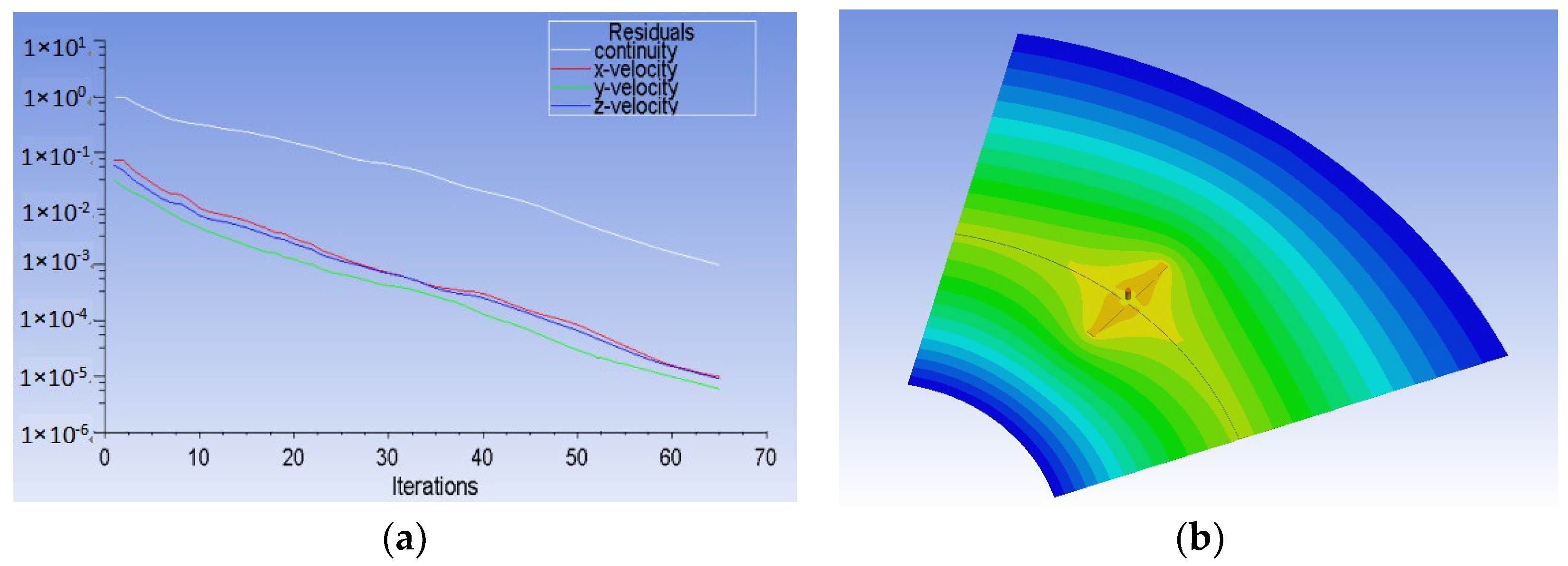
4. Comparative Analysis and Comparison of Simulation Results

4.1. Sliced Structured Mesh

After calculate the flow field, the residual curve is shown in Figure 9a, the model converges after 156 iterative calculation steps, and the cloud charts of pressure distribution of gas film are shown in Figure 8b.

4.2. Continuous Structured Mesh

After calculate the flow field, the residual curve is shown in Figure 10a, the model is iteratively calculated after 65 steps and the convergence ends, and the cloud charts of pressure distribution of gas film are shown in Figure 10b.

4.3. Unstructured Mesh

After calculate the flow field, the residual curve is shown in Figure 11a, and the model is iterated to about 75 steps, and the curve begins to oscillate. After 300 iterations, calculate and compare the inlet and outlet flow of the model. The result is shown in Figure 11b. The difference between the inlet and outlet flow rates is 2.738 × 10⁻⁶ kg/s, which only accounts for 0.042% of the inlet flow rate, so the calculation can be considered to have reached convergence. The cloud charts of pressure distribution of gas film are shown in Figure 11b.

4.4. Comparison of Simulation Using Different Meshes

(1)
Quality of the mesh
Mesh quality is an essential indicator for evaluating the results of meshing. Comparing the structured and unstructured meshes that are also sliced and then divided, the number of elements of the structured mesh is 44,955, which is only 1/3 of the unstructured mesh, but the average orthogonal quality of the mesh is 0.99147. The average skewness is 6.7402 × 10⁻², compared with the average orthogonal quality of the unstructured mesh, 0.84881, and the average skewness, 0.24597, the mesh quality has improved significantly. By comparing the residual curve calculations, it can be found that the residual curve of the unstructured mesh has the phenomenon of oscillation and non-convergence, while the structured mesh is better at convergence. Thus, it is not hard to obtain structured meshes that can use a smaller number of elements to achieve higher mesh quality.
(2)
Computational efficiency
Obviously, due to the oscillation of the residual curve of unstructured mesh, the computational efficiency has been dramatically affected. For structured mesh, the continuous structured mesh only needs 65 steps to complete the calculation, which is much faster than the 156 steps of the sliced structured mesh. However, one thing that needs to be considered is that using slicing to divide the mesh for more complex structures is much simpler than divide the continuous structured mesh, thereby reducing the pre-processing time. Therefore, we can comprehensively consider these factors when selecting the mesh method.
(3)
Calculation accuracy
The pressure distribution of the three meshes is basically the same at the thrust surface of the bearing. The main difference lies in the pressure distribution near the orifice and throttle groove. For sliced structural mesh, as shown in Figure 12, because the sliced structural mesh is divided separately by the slicing method, the meshes are not continuous at the interface, resulting in an unsmooth pressure gradient at the interface of the orifice and the throttle groove, which results in a particular calculation error.

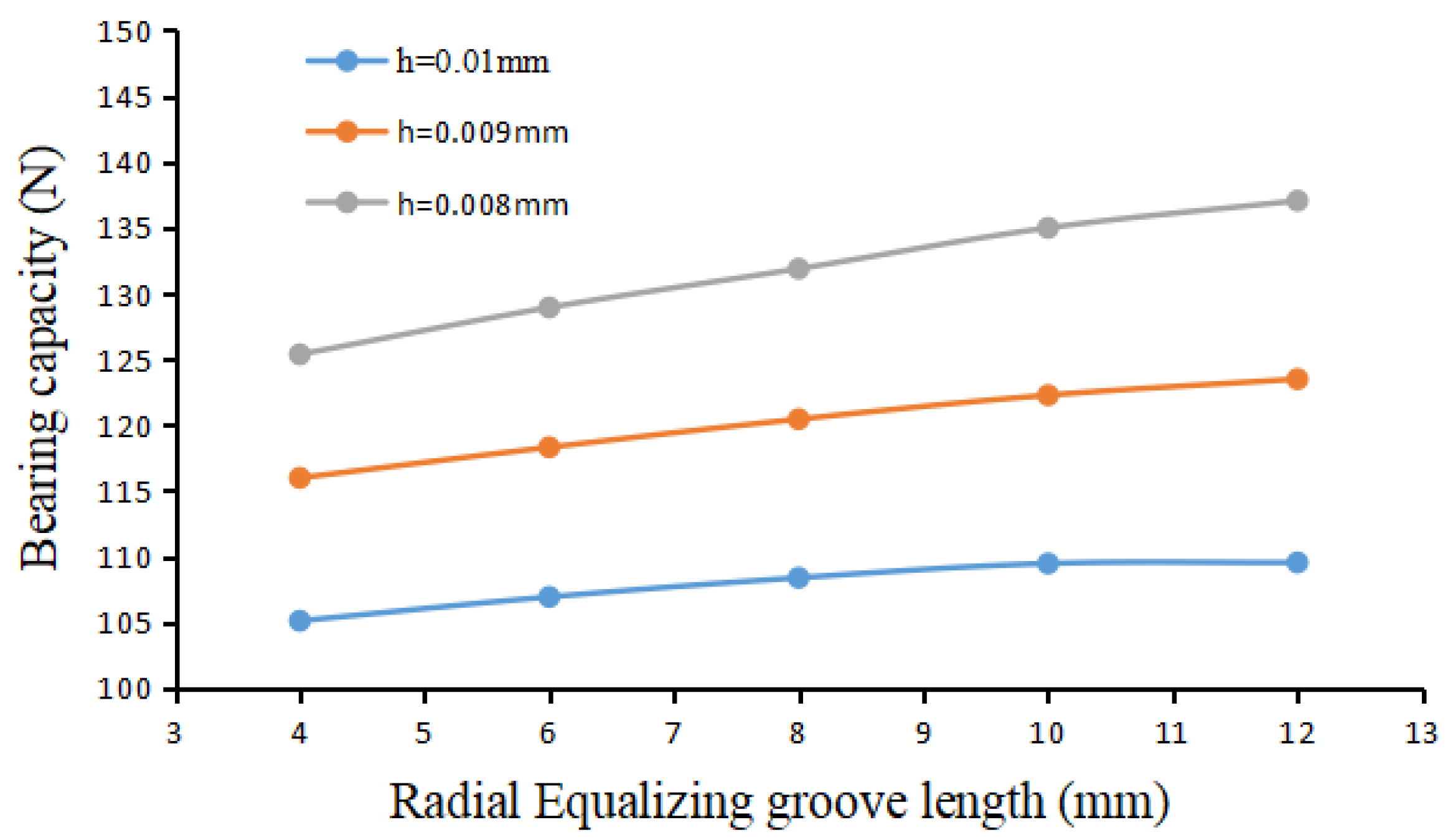
5. Influence of Radial Equalizing Groove Parameters

Based on the above research, this section uses continuous structural mesh when meshing the bearing and further studies the influence of the size of the radial equalizing groove on the bearing capacity of a symmetrical multi-throttle thrust bearing. The comparative study analyzes the degree of influence of radial equalizing groove length Lg, radial equalizing groove width bg, radial equalizing groove depth hg, and gas film thickness h on bearing capacity W. Different radial equalizing groove size parameters are set between each group. In contrast, the other bearing parameters are unchanged. The setting dimensions are as follows: bearing inner radius R2 = 10 mm, outer radius R1 = 35 mm, orifice distribution circle radius R3 = 20 mm, orifice diameter d = 0.3 mm, the number of orifices is 6, and the orifice air supply pressure 0.5 MPa.

5.1. The Influence of Radial Equalizing Groove Length on Bearing Capacity

Three simulation experiments are set up according to the gas film thickness h = 8 μm, 9 μm, and 10 μm, respectively. In each set of simulations, the radial equalizing groove width bg is 0.6 mm and the radial equalizing groove depth hg is 0.05 mm. The lengths of the radial equalizing groove in each group are respectively set to Lg = 4 mm, 6 mm, 8 mm, 10 mm, and 12 mm. According to the simulation results, the relationship between the radial groove length and the bearing capacity is drawn, as shown in Figure 13. It can be seen from the graph that as the air film thickness h decreases, the bearing capacity increases, and the air film pressure increases rapidly. Therefore, the smaller the air film gap, the higher the bearing capacity; at the same time, as the length Lg of the radial equalizing groove increases, the bearing capacity also gradually increases, and as the length Lg of the radial equalizing groove increases, the increasing trend of the bearing capacity becomes slower.
Figure 14 shows the cloud diagram of gas film pressure distribution under radial equalizing grooves of different lengths. It can be seen from the figure that as the length Lg of the radial equalizing groove increases, the area of the high-pressure zone is gradually increasing. When the length of the radial equalizing groove Lg is short, the high-pressure area of the gas film is only concentrated in the vicinity of the radial equalizing groove. As the groove length Lg increases, the high-pressure zone of the gas film spreads radially and axially with the orifice as the center. However, when the groove length Lg is too long because the two ends of the radial equalizing groove are too close to the inner and outer diameter edges of the bearing, the pressure at the end of the radial equalizing groove decreases, and the pressure at the same radius on the radial equalizing groove increases with the groove length Lg. Instead, it decreases. Therefore, under the combined influence of the above factors, the air film bearing capacity W and the length of the radial equalizing groove Lg show that, as the length of the radial equalizing groove Lg increases, the bearing capacity W also gradually increases, and as the length of the radial equalizing groove Lg increases, the load-bearing capacity W increases and the trend becomes slower.
The length Lg of the radial equalizing groove should not be too large in the design. In the design, it is generally necessary to ensure that the total volume of the air cavity occupies between 2% and 10% of the total volume of the air film to ensure the stability of the bearing thereby. When the length Lg of the radial equalizing groove is too large, it is easier to produce self-excited vibration of the air hammer.

5.2. The Influence of Radial Equalizing Groove Width on Bearing Capacity

According to the gas film thickness h = 8 μm, 9 μm, 10 μm, three simulation experiments are prepared, respectively. In each set of simulations, the radial equalizing groove length Lg is 10 mm, and the radial equalizing groove depth hg is 0.05 mm. The widths of the radial equalizing groove in each group are respectively set as bg = 0.4 mm, 0.5 mm, 0.6 mm, 0.7 mm, 0.8 mm. According to the simulation results, the relationship between the radial groove width bg and the bearing capacity W is drawn, as shown in Figure 15. It can be seen from the graph that as the groove width bg of the radial equalizing groove increases, the bearing capacity of the bearing increases correspondingly, but the influence of the groove width bg of the radial equalizing groove on the bearing capacity is minimal. When the gas film thickness h is 10 μm, the difference between the bearing capacity of a bearing with a groove width bg of 0.8 mm and the bearing capacity W of a bearing with groove width bg of 0.4 mm is only 1.5 N. In consideration of reducing the volume of the air cavity to ensure the stability of the bearing, a minor groove width bg can be selected in the design.

5.3. The Influence of Radial Equalizing Groove Depth on the Bearing Capacity

According to the gas film thickness h = 8 μm, 9 μm, 10 μm, three simulation experiments are prepared, respectively. In each set of simulations, the radial equalizing groove length Lg is 10 mm, and the radial equalizing groove depth hg is 0.05 mm. The depths of the radial equalizing groove in each group are respectively set as hg = 40 μm, 50 μm, 60 μm, 70 μm, 80 μm. According to the simulation results, the relationship between the radial groove depth hg and the bearing capacity W is drawn, as shown in Figure 16. It can be seen from the graph that as the depth hg of the radial equalizing groove increases, the bearing capacity W of the bearing increases correspondingly. When the thickness h of the air film is smaller, the increase in the depth hg of the radial equalizing groove has a more significant influence on the bearing capacity W. This is because the air film gap is small, and the difference in h between the depth hg of the radial equalizing groove and the air film thickness becomes more prominent, and the effect of surface throttling is relatively apparent. When the air film thickness h = 10 μm, as the bearing groove depth hg increases from 40 μm to 80 μm, the bearing capacity increases by 10.59 N. When the air film thickness h = 8 μm, the bearing capacity increment reaches 16.28 N, about 1.5 times higher than when the air film thickness h = 10 μm.

5.4. Verifications

In Ref. [18], the researchers conducted an experimental analysis of the static characteristics of a thrust bearing with circumferential pressure equalizing grooves and orifices and plotted the load-carrying capacity curves under different gas film thicknesses. Compared with reference [18], the thrust bearing structure studied in this paper only adds radial pressure equalizing grooves, and the rest of the structure is the same, so that it can be directly compared with the experimental data in Ref. [18].
Since the thickness of the gas film studied in this paper ranges from 8 μm to 10 μm, the gas film thicknesses are selected as 5 μm, 6 μm, 7 μm, 8 μm, 9 μm, and 10 μm in the comparison and verification, and the rest of the structural parameters are set according to reference [18]. During the simulation, the smallest symmetrical part of the gas film is taken again and continuous structural mesh is used when meshing the bearing. Figure 17 compares the simulation results with the experimental results in Ref. [18]. It is not difficult to see that the simulation results are in good agreement with the experiments, which proves that the simulation analysis method and calculation results in this paper have high accuracy.

6. Conclusions

The paper takes symmetrical multi-throttle thrust bearing as the research object, uses three methods to divide the mesh, and conducts simulation comparison analyses. The analyses’ results show that the unstructured mesh will oscillate and fail to converge in calculating the residual curve, and the sliced structural mesh is divided simply, but its calculation speed and accuracy are slightly inferior to the continuous structure grid. On this basis, a continuous structural mesh is used to divide the bearing, and the influence of the radial throttle groove on the pressure distribution and static characteristics of the bearing is studied. The analyses’ results show that the thickness of the air film h has the most significant influence on the bearing capacity, the length Lg and depth hg of the throttle groove also have a significant influence on the bearing capacity, while the width of the throttle groove has a weak influence on the bearing capacity. Thus, at a particular air cavity volume, priority should be given to reducing the width of the throttle groove and increasing the length and depth of the throttle groove to improve the bearing capacity. These works guide the design and simulation of symmetrical multi-throttle thrust bearings.

Author Contributions

Conceptualization, Y.L.; writing—original draft preparation, Z.C.; methodology D.W.; validation, Y.Z.; investigation, X.W.; supervision, C.S. All authors have read and agreed to the published version of the manuscript.

Funding

This research was funded by the National Natural Science Foundation major research projects of China (grant number 91960109), the National Natural Science Foundation of China (grant number 51805117), the China postal Postdoctoral Science Foundation (grant number 2019M651279), the Heilongjiang Postdoctoral Fund (grant number LBH-Z18078), the scientific and technological cooperation project of Heilongjiang Provincial Academy of Sciences (grant number YS19A15).

Institutional Review Board Statement

Not applicable.

Informed Consent Statement

Not applicable.

Data Availability Statement

Not applicable.

Acknowledgments

The author thanks the National Natural Science Foundation major research projects of China (grant number 91960109), the National Natural Science Foundation of China (grant number 51805117), the China postal Postdoctoral Science Foundation (grant number 2019M651279), the Heilongjiang Postdoctoral Fund (grant number LBH-Z18078), the scientific and technological cooperation project of Heilongjiang Provincial Academy of Sciences (grant number YS19A15)for funding and the experimental equipment support from Center of Ultra-precision Optoelectronic Instrument Engineering.

Conflicts of Interest

The authors declare no conflict of interest.

References

  1. Wu, L.; Leng, J.; Ju, B. Digital Twins-Based Smart Design and Control of Ultra-Precision Machining: A Review. Symmetry 2021, 13, 1717. [Google Scholar] [CrossRef]
  2. Li, Z.; Shi, Y. Multi-Objective Parameter Optimization for Disc Milling Process of Titanium Alloy Blisk Channels. Symmetry 2019, 11, 173. [Google Scholar] [CrossRef] [Green Version]
  3. Sarhan, A. Investigate the spindle errors motions from thermal change for high-precision CNC machining capability. Int. J. Adv. Manuf. Technol. 2014, 70, 957–963. [Google Scholar] [CrossRef]
  4. Zha, J.; Chen, Y.; Zhang, P. Precision design of hydrostatic thrust bearing in rotary table and spindle. Proc. Inst. Mech. Eng. Part B-J. Eng. Manuf. 2018, 232, 2044–2053. [Google Scholar] [CrossRef]
  5. Fang, C.; Huo, D.; Huang, X. A comprehensive analysis of factors affecting the accuracy of the precision hydrostatic spindle with mid-thrust bearing layout. Int. J. Adv. Manuf. Technol. 2021, 10, 949–967. [Google Scholar] [CrossRef]
  6. Zhao, B.; Wang, L.; Tan, J.; Sun, C. Aircraft Engine Rotor Assembly Method and Device. Patent WO2015120749 A1, 7 August 2017. [Google Scholar]
  7. De Santis, M.; Silvestri, L.; Forcina, A.; Di Bona, G.; Di Fazio, A.R. Preliminary Realization of an Electric-Powered Hydraulic Pump System for a Waste Compactor Truck and a Techno-Economic Analysis. Appl. Sci. 2021, 11, 3033. [Google Scholar] [CrossRef]
  8. Sahto, M.; Wei, W.; He, L.; Imran, M.; Gong, W. Modelling and Simulation of Aerostatic Thrust Bearings. IEEE Access 2020, 99, 121299–121310. [Google Scholar] [CrossRef]
  9. Yan, R.; Wang, L.; Wang, S. Investigating the influences of pressure-equalizing grooves on characteristics of aerostatic bearings based on CFD. Ind. Lubr. Tribol. 2019, 71, 4. [Google Scholar] [CrossRef]
  10. Gao, S.; Shi, Y.; Xu, L.; Chen, H.; Cheng, K. Investigation on influences of herringbone grooves for the aerostatic journal bearings applied to ultra-high-speed spindles. Proc. Inst. Mech. Eng. Part C-J. Eng. Mech. Eng. Sci. 2019, 16, 5795–5812. [Google Scholar] [CrossRef]
  11. Cui, H.; Wang, Y.; Wang, B.; Yang, H.; Xia, H. Numerical Simulation and Experimental Verification of the Stiffness and Stability of Thrust Pad Aerostatic Bearings. Chin. J. Mech. Eng. 2018, 02, 186–197. [Google Scholar] [CrossRef] [Green Version]
  12. Zhou, Y.; Chen, X.; Chen, H. A hybrid approach to the numerical solution of air flow field in aerostatic thrust bearings. Tribol. Int. 2016, 102, 444–453. [Google Scholar] [CrossRef]
  13. Ma, W.; Cui, J.; Liu, Y.; Tan, J. Improving the pneumatic hammer stability of aerostatic thrust bearing with recess using damping orifices. Tribol. Int. 2016, 103, 281–288. [Google Scholar] [CrossRef]
  14. Yadav, S.; Rajput, A.; Ram, N.; Sharma, S.; Gachot, C. A novel technique to compute static and dynamic performance characteristics of aerostatic thrust bearing. Ind. Lubr. Tribol. 2017, 70, 84–96. [Google Scholar] [CrossRef]
  15. Müller, C.; Greco, S.; Kirsch, B.; Aurich, J. A Finite Element Analysis of Air Bearings Applied in Compact Air Bearing Spindles. Procedia CIRP 2017, 58, 607–612. [Google Scholar] [CrossRef]
  16. Chang, S.; Chan, C.; Jeng, Y. Numerical analysis of discharge coefficients in aerostatic bearings with orifice-type restrictors. Tribol. Int. 2015, 90, 157–163. [Google Scholar] [CrossRef]
  17. Wei, L.; Ruibo, Y.; Jing, L. Computational Fluid Dynamics of aerostatic bearings with the finite volume method. In Proceedings of the 2011 IEEE 5th International Conference on Robotics, Automation and Mechatronics (RAM), Qingdao, China, 17–19 September 2011; pp. 270–274. [Google Scholar] [CrossRef]
  18. Belforte, G.; Colombo, F.; Raparelli, T.; Trivella, A.; Viktorov, V. Comparison between grooved and plane aerostatic thrust bearings: Static performance. Meccanica 2011, 46, 547–555. [Google Scholar] [CrossRef] [Green Version]
Figure 1. UOI Ultra-precision rotor shape and position error measurement system.
Symmetry 14 00351 g001
Figure 2. Structure diagram of a symmetrical multi-throttle thrust bearing.
Symmetry 14 00351 g002
Figure 3. Schematic diagram of dimensional parameters of a bearing.
Symmetry 14 00351 g003
Figure 4. 1/6 Air film model of a symmetrical multi-throttle thrust bearing.
Symmetry 14 00351 g004
Figure 5. Structured mesh and unstructured mesh.
Symmetry 14 00351 g005
Figure 6. Mesh division result and division quality: (a) structural overall mesh; (b) local refinement of the mesh at the inlet; (c) mesh orthogonal mass distribution; (d) mesh skewness distribution.
Symmetry 14 00351 g006aSymmetry 14 00351 g006b
Figure 7. Mesh division result and division quality: (a) structural overall mesh; (b) local refinement of the mesh at the intake; (c) mesh Jacobian determinant check; (d) mesh Erickson skewness check.
Symmetry 14 00351 g007
Figure 8. Mesh division result and division quality: (a) structural overall mesh; (b) local refinement of the mesh at the intake; (c) mesh orthogonal mass distribution; (d) mesh skewness distribution.
Symmetry 14 00351 g008
Figure 9. Analysis results of sliced structured mesh: (a) residual curve; (b) pressure distribution cloud chart.
Symmetry 14 00351 g009
Figure 10. Analysis results of continuous structured mesh: (a) residual curve; (b) pressure distribution cloud chart.
Symmetry 14 00351 g010
Figure 11. Unstructured mesh analysis results: (a) residual curve; (b) comparison of import and export flow; (c) pressure distribution cloud chart.
Symmetry 14 00351 g011aSymmetry 14 00351 g011b
Figure 12. Pressure distribution at the interface of the orifice and the throttle groove.
Symmetry 14 00351 g012
Figure 13. The influence of radial equalizing groove length on bearing capacity.
Symmetry 14 00351 g013
Figure 14. Cloud diagram of gas film pressure distribution under pressure radial equalizing grooves of different lengths: (a) length of radial equalizing groove Lg = 4 mm; (b) length of radial equalizing groove Lg = 6 mm; (c) length of radial equalizing groove Lg = 8 mm; (d) length of radial equalizing groove Lg = 10 mm.
Symmetry 14 00351 g014
Figure 15. The influence of radial equalizing groove width on bearing capacity.
Symmetry 14 00351 g015
Figure 16. The influence of radial equalizing groove depth on the bearing capacity.
Symmetry 14 00351 g016
Figure 17. The comparison results of bearing capacity between simulation and previous.
Symmetry 14 00351 g017
Publisher’s Note: MDPI stays neutral with regard to jurisdictional claims in published maps and institutional affiliations.

