
Two Modified Chaotic Maps Based on Discrete Memristor Model


1
School of Mathematics and Computational Science, Guilin University of Electronic Technology, Guilin 541004, China
2
School of Information and Software Engineering, University of Electronic Science and Technology of China, Chengdu 610054, China
*
Author to whom correspondence should be addressed.
Symmetry 2022, 14(4), 800; https://doi.org/10.3390/sym14040800
Submission received: 14 March 2022
/
Revised: 1 April 2022
/
Accepted: 8 April 2022
/
Published: 12 April 2022
Abstract
:The discrete memristor has aroused increasing interest. In this paper, two discrete memristors with cosine with amplitude memristance are designed based on the discrete memristor model. The Simulink models of the two discrete memristors are built to verify that they meet the definition of the memristor. To improve the dynamic of a classic chaotic map, the discrete memristors are introduced into two chaotic maps: a Logistic map and a Hénon Map. Through the trajectory analysis, Lyapunov exponent, bifurcation diagram, and complexity analysis, it is shown that discrete memristors can indeed make the dynamical behaviors of chaotic maps richer and more complex.
1. Introduction
The memristor is a basic circuit element that represents the relationship between magnetic flux and electric charge, and has the memory function [1]. The first memristor mathematical model was presented by Chua in 1971 [2]. However, Prof. Chua did not find suitable materials to implement the memristor at that time. Then, in 2008, HP laboratory realized the physical memristor model using nanoscale electronic devices [3]. Since then, the memristor has attracted the attention of many scholars. In hardware implementation of memristors, remarkable work has been carried out [4,5,6,7,8,9]. Moreover, the memristor is applied in many fields such as neural networks [10,11,12], electrical engineering [13,14,15], secure communications [16], etc.
The chaotic system is a nonlinear dynamic system that has a seemingly random irregular motion [17]. Since it has the ability to generate pseudo-random sequences with unpredictability and sensitivity, the chaotic system is often used in the field of communication security [17,18,19,20]. The memristor has natural nonlinearity, which is controlled by charge or flux. The memristor can be used to construct the memristor circuits with complex chaotic oscillations [21]. Therefore, the application of memristor in the chaotic system catches the attention of many scholars. There are many theoretical studies and experimental studies about the application of a continuous memristor [22,23,24]. In recent years, the application of the discrete memristor in discrete chaotic systems has aroused increasing interest because the discrete mode is more suitable for digital circuits and discrete systems. Based on the fractional-order theory, He [25] designed the discrete fracmemristor and introduced it into the Sine map to obtain the fracmemristor sine map. Bao [26] presented a discrete memristor with cosine memductance through a sampling memristor–capacitor circuit. Bao [27] presented the discrete memristor model and discrete memristor mapping model, created four discrete memristor maps, and studied their dynamic behaviors. Peng [28] created three discrete memristor-based fractional-order chaotic maps based on Caputo fractional-order difference and found they had complex dynamic behaviors. Fu [29] introduced the discrete memristor into the Lorenz map and built the Simulink model of the map.
Classical chaotic maps such as the Hénon map and Logistic map usually have the weaknesses of a small parameter range and low complexity. Therefore, inspired by previous brilliant works, this paper introduces discrete memristor model into two classical discrete maps to improve their dynamic behavior. Moreover, this paper constructs a Simulink model of a discrete memristor and a discrete memristor-based map. The main contributions of this paper are as follows:
- Based on the discrete memristor model, two discrete memristors with cosine with amplitude memristance are designed. The Simulink models of these two memristors are constructed to verify that they meet the definition of the memristor.
- Two modified chaotic maps based on the above memristors are designed. The Simulink models of these two discrete memristor-based maps are constructed to verify their achievability.
- Through trajectory analysis, a Lyapunov exponent, a bifurcation diagram, and complexity analysis, the dynamical behaviors of discrete memristor-based maps are evaluted and the role of discrete memristors are analyzed.
The structure of this paper is as follows. In Section 2, two discrete memristors with cosine memductance are presented and their Simulink models are built. In Section 3, a modified Logistic map based on a discrete memristor is designed and its dynamic behaviors are analyzed. In Section 4, a modified Hénon map based on a discrete memristor is designed and investigated. Lastly, the significant conclusions are summarized.
2. Two Discrete Memristors and Simulink Models
The definition of the discrete memristor was deduced by He [25] by introducing the difference in the charge-controlled continuous memristor, as shown in Equation (1).
where is the voltage of the memristor of n moment. is the input current of n moment and k is a constant. is the memristance.
From , get
where is the initial state of the discrete memristor. Fu [29] writes the form of the discrete memristors as shown in Equation (3).
In the discrete mode, the memristor is equivalent to an accumulator. Then, this paper sets the memristance as the cosine function with amplitude. That is, and the discrete memristor is as shown in Equation (4).
where is the amplitude. The relationship between the voltage v and the current i from Equation (5) is shown.
The memristor state is controlled by the initial state , the parameter k, and the amplitude . This paper studies the discrete memristor by examining two sets of values: and . The models are as Equations (6) and (7) shown.
The Simulink model of the discrete memristor model Equation (5) is exhibited in Figure 1. The Simulink model consists of a unit delay block, a sum block, a memory block, two gain blocks, an add block, a product block, a sine-wave block, a constant block, and a cosine function block. The sine-wave block is the input current. A sum block and a memory block form an accumulator. The Gain1 block and the Gain2 block represent the parameter k and , respectively. The constant block represents the initial state of memristor . The XY graph block can observe the current–voltage characteristic curves. The memristor models Equations (6) and (7) can be obtained by changing the values of Gain1 and Gain2 blocks. The sine wave block can adjust the frequency and amplitude of the input current.
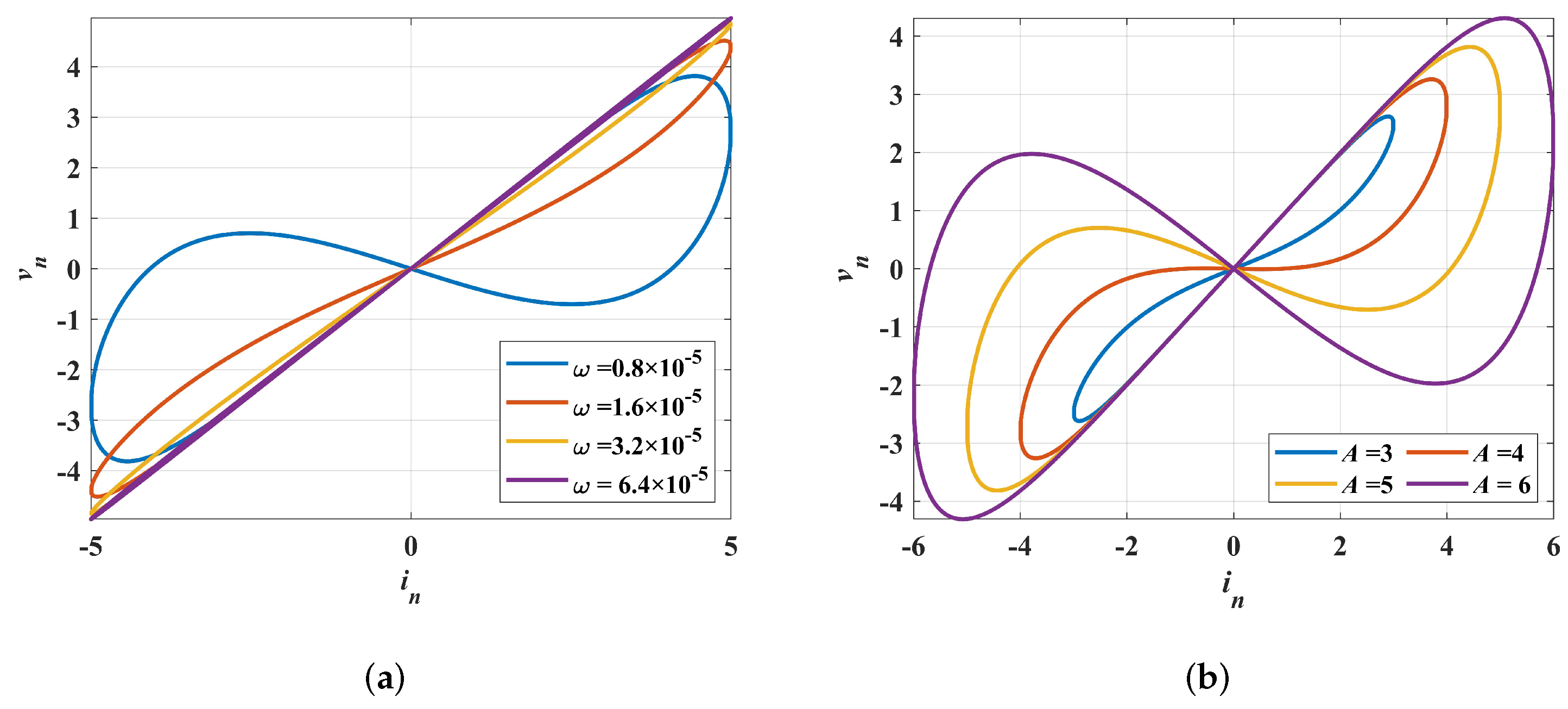
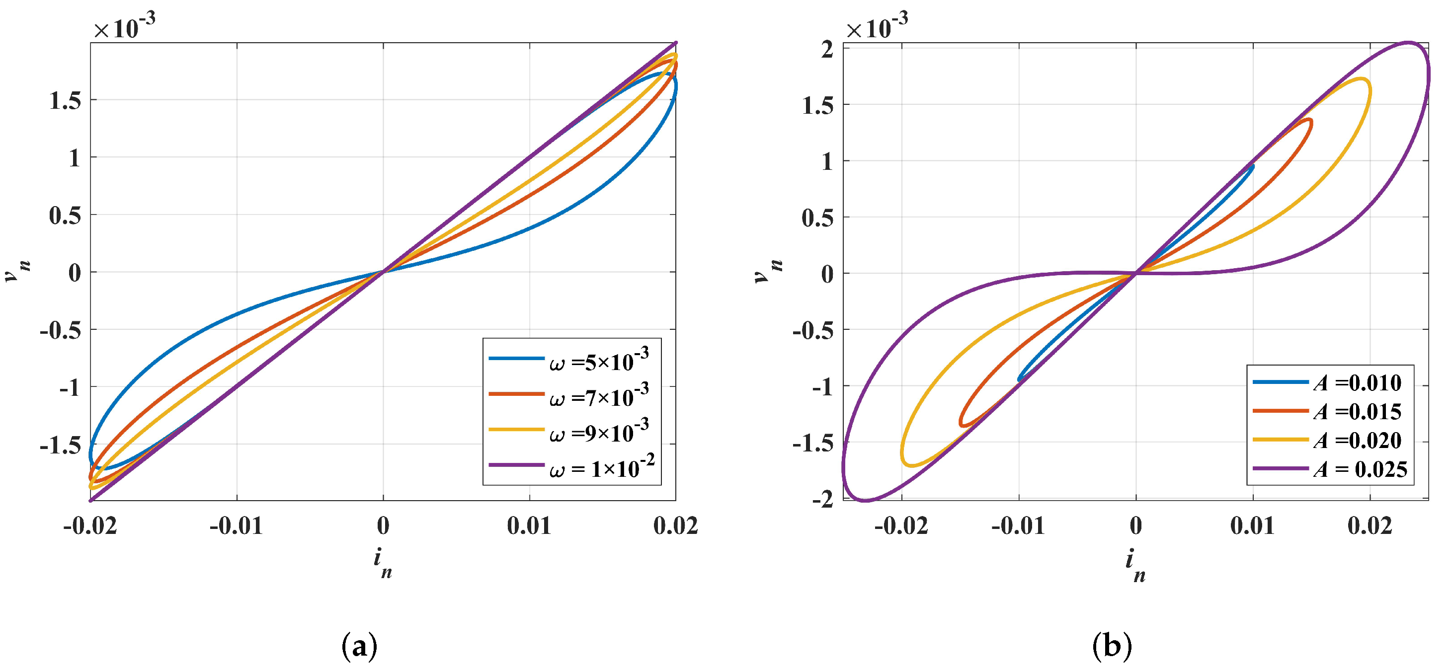
To prove that the two memristors meet the definition of a memristor, the sine signals with different amplitudes and frequencies are inputted to the memristor models through the Simulink model and the current–voltage characteristic curves are exhibited in Figure 2 and Figure 3. From the four subfigures, the current–voltage characteristic curves all exhibit the pinched hysteresis loop. Set and , , the current–voltage characteristic curves of memristor Equation (6) are shown in Figure 2a. Set and , the current–voltage characteristic curves of memristor Equation (7) are shown in Figure 3a. When the amplitudes are fixed, for both memristor models, the area of the pinched hysteresis lobe decreases with increasing frequencies and finally degenerates into linear devices. Set and , the current–voltage characteristic curves of memristor Equation (6) are shown in Figure 2b. Set and , the current–voltage characteristic curves of memristor Equation (7), are shown in Figure 3b. When the frequencies are fixed, for both memristor models, the area of the pinched hysteresis lobe decreases with increasing amplitudes and finally degenerates into linear devices. Hence, the two discrete memristor models have the three fingerprints of the memristor in [30], which can be can be further studied.
3. The Modified Logistic Map Based on the Discrete Memristor
In this part, the discrete memristor-based Logistic map is introduced and its Simulink model is built. Then the dynamical behavior of the DM-Logistic map and the original Logistic map are studied using trajectory analysis, the Lyapunov exponent, a bifurcation diagram, and complexity analysis.
3.1. Discrete Memristor-Based Logistic Map Mathematical Model and Simulink Model
The Logistic map [31] is a simple one-dimensional chaotic map. The definition of the Logistic map is as shown in Equation (8).
where a is the control parameter. When , the map is a in chaos state.
This section introduces the discrete memristor into the Logistic map, making a discrete memristor-based Logistic map (DM-based Logistic map). The input of the discrete memristor model is set as the sequence and the output of the discrete memristor model is as shown in Equation (9).
where the is also a sequence. Let the discrete memristor (i.e., the output of the discrete memristor) multiply the term in of Equation (8). The mathematical model of DM-based Logistic map is defined as:
where a is the system control parameter, k is the memristor parameter, and is the initial of the memristor. Set . Let the accumulator in the discrete memristor separate into a sequence, then the DM-based Logistic map can be written in the following form:
where . The state of the DM-based Logistic map is dependent on system parameter a, system initial , memristor parameter k, and memristor initial . Fixed , then the map Equation (11) is modified based on the discrete memristor Equation (6). To study the dynamic behaviors of the DM-based Logistic map, the following paper analyzes the trajectory, the Lyapunov exponent, the bifurcation diagram, and complexity analysis relying on the four factors.
The Simulink model of the DM-based Logistic map is exhibited in Figure 4. The unit delay block and the unit delay1 block represent the and , respectively, which can set the initial value of the sequence. The gain block represents the parameter k. The sequence can be observed in the scope block. The constant blocks represent the memristor initial and the system parameter a. The map state can be controlled by the unit delay block, the Gain block, and the constant blocks.
3.2. Trajectory Analysis
To analyze the trajectory of the DM-based Logistic map, the Simulink simulation trajectory diagrams are plotted in Figure 4. Here, set . Figure 5a shows the time-sequence diagram iterated 10,000 times, which proves that the map has good ergodicity. Figure 5b,c show the time sequences iterated 20 times for slightly different parameters of the DM-based Logistic map and the Logistic map, respectively. The two sequences are separated at the 14th iteration in Figure 5b, while the two sequences are not separated in Figure 5c, which means that DM-based Logistics are more sensitive than the original map. Figure 6 shows the Simulink simulation 3D phase plane of the DM-based Logistic map and the original map. It is clearly seen that the trajectory of the DM-based Logistic map is more complex than that of the original map, showing that the DM-based Logistic map has greater unpredictability.
3.3. Lyapunov Exponent and Bifurcation Diagram
The Lyapunov exponent (LE) [32] and the bifurcation diagram [33] are the important indicators to verify the dynamic state of chaos. In this paper, the Jacobian matrix method [34] is used to calculate the Lyapunov exponent. In this part, the paper researches the Lyapunov exponent and bifurcation diagram, relying on the four factors mentioned previously.
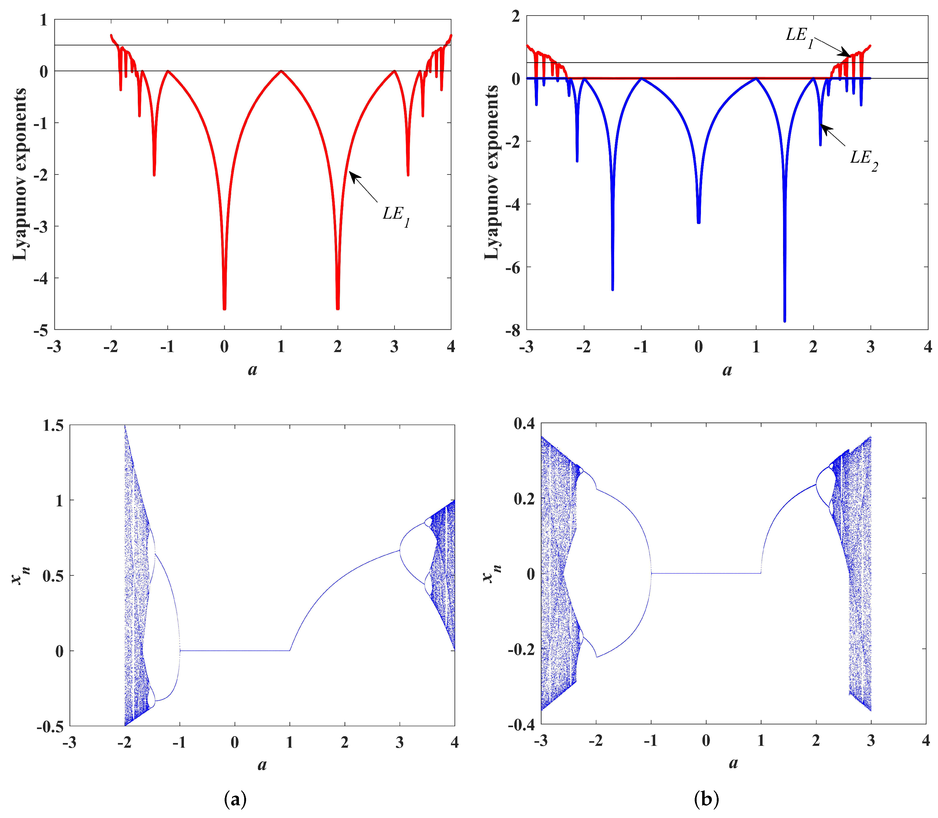
The initials are set as and the memristor parameter is set as . When the system parameter a is varied in the region , the LEs and bifurcation diagrams of the DM-based Logistic map and the Logistic map are plotted in Figure 7. As can be observed, the effective value of parameter a of the DM-based Logistic map is , and that of the Logistic map is . As for the LEs values, both of the maps are approximately symmetrical. The axis of symmetry of the DM-based Logistic map is , while that of the original map is . It is worth noting that the chaos region of DM-based Logistic is wider than that of Logistic map . The general trend of the LE value for both maps is to increase with the absolute value of parameter a. The largest of the DM-based Logistic map is when , while that of the original Logistic map is when .
The initial is set as and the parameter is set as . The parameter of the Logistic map is set as and the parameter of the DM-based Logistic map is set as . When system initial is varied in the region , the LEs and bifurcation diagrams of the DM-based Logistic map and the Logistic map are plotted in Figure 8. It is clear that the chaos region of the DM-based Logistic map is much wider than that of the Logistic map . Numerically, LE values oscillate smoothly, indicating that the initial value in the chaos region of both maps has little effect on the degree of chaos.
When the parameter a is fixed to , the map initial is fixed to and the memristor parameter k is fixed to . The LEs and bifurcation diagram relying on memristor initial are shown in Figure 9. In Figure 9, it is interesting to find that several shapes resembling the letter “H” appear in the bifurcation diagram, and the interval between each “H” is slightly different but approximately 3.2. The length of each “H” is also slightly different, but approximately 3.1. The situation seems like the chaotic region with periodicity, but not precise periodicity. However, memristor initial has a large range of spaces but also has little effect on the degree of chaos.
When the parameter a is fixed to , the map initial is fixed to and the memristor initial is fixed to , the LEs and bifurcation diagram relying on memristor parameter k are shown in Figure 10. As can be observed, the chaos region is and has little effect on on the degree of chaos.
To summarize the above experiments, the chaos range of parameters values for DM-based Logistic map and the original Logistic map are shown in Table 1.
3.4. Complexity Analysis
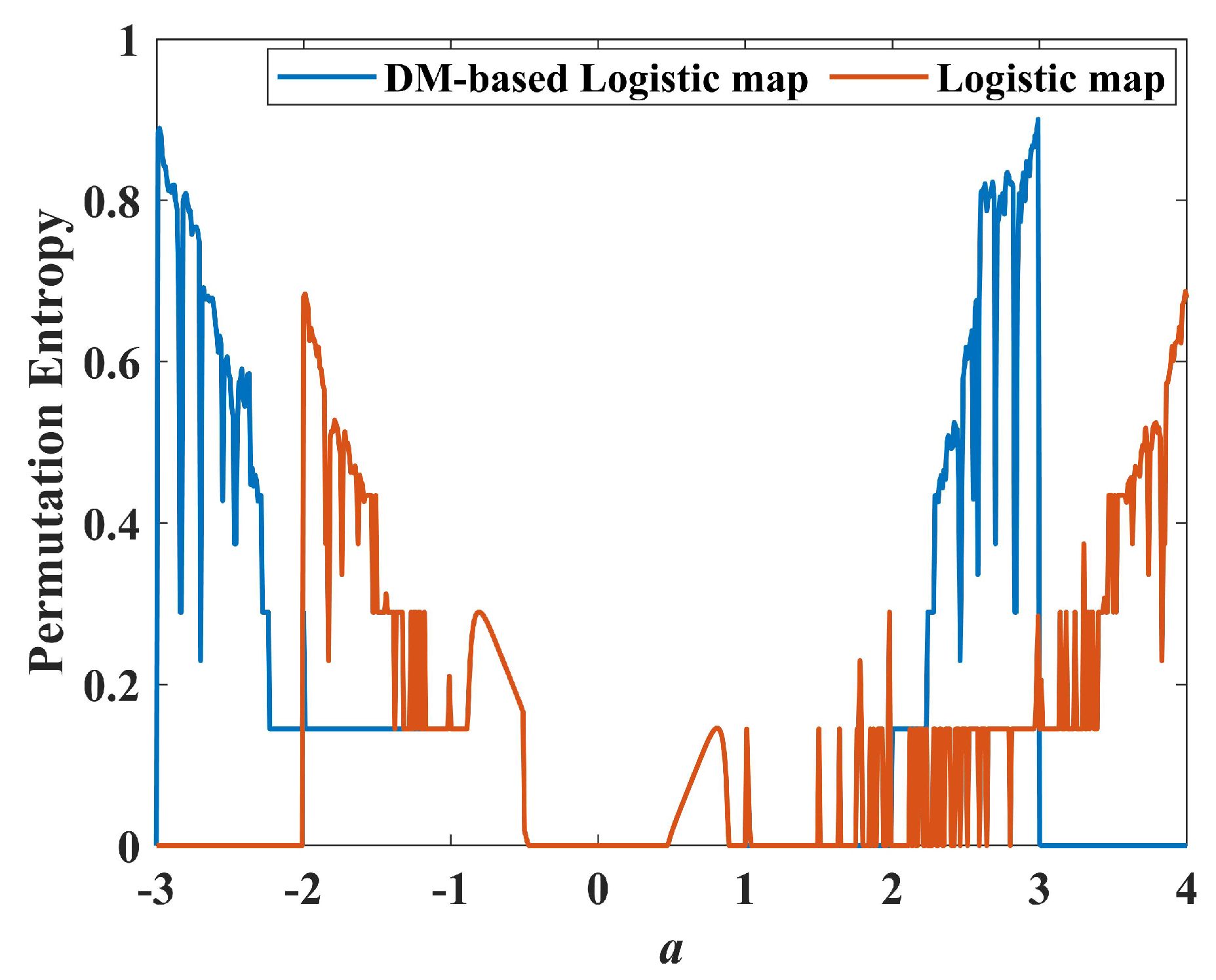
In the application of cryptography, the randomness of the chaotic time series is better. This paper uses permutation entropy(PE) [35] to test the complexity of the chaotic sequence. The PE value is closer to 1, indicating the sequence complexity is higher. The permutation entropy of the DM-based Logistic map and the Logistic map for is plotted in Figure 11, in which the blue line and the red line represent the PE of the DM-based Logistic map and the Logistic map, respectively. The region of the DM-based Logistic map with PE values above 0.6 is , while that of the original Logistic map is . It is clear that the region of high complexity of the DM-based Logistic map is wider than that of the original Logistic map. The highest PE value of the DM-based Logistic map is 0.9005 at , while that of the original Logistic map is only 0.6871. Therefore, the discrete memristor improves the complexity of the Logistic map.
4. The Modified Hénon Map Based on the Discrete Memristor
In this part, the discrete memristor-based Hénon map (DM-based Hénon) is introduced and its Simulink model is built. Then, we study the dynamical behavior of the DM-based Hénon map and the original Hénon map by trajectory analysis, Lyapunov exponent, bifurcation diagram, and complexity analysis.
4.1. Discrete Memristor-Based Hénon Map Mathematical Model and Simulink Model
The Hénon map is a discrete two-dimensional chaotic map, introduced by Michel Hénon in 1969 [36]. First, the Hénon map was presented for researching the problem that a system with two degrees of freedom can be reduced to the study of area-preserving mapping [36]. In 1976, Hénon carried out numerical experiments for a set parameter and found that the Hénon map has a strange attractor, which has the same basic properties as the Lorenz system [37]. The equation of the Hénon map is defined as
where are the control parameters. The two parameters control the stretching and folding states of the chaotic attractor [38]. When and , the map is in a chaotic state. The classical Hénon map has the disadvantages of small parameter range and low complexity.
This section introduces the discrete memristor into the Hénon map, making a discrete memristor-based Hénon map (DM-based Hénon map). The input of the discrete memristor model is set as the sequence and the output of discrete memristor model is as shown in Equation (13).
where the is also a sequence.
The discrete memristor (i.e., the ) is multiplied by the term of in of Equation (12). The mathematical model of DM-based Hénon is defined as shown in Equation (14).
where are the system control parameters, is the memristor initial and k is the memristor parameters. Here, set . Fixed , then the map Equation (14) is modified based on the discrete memristor Equation (7). Let the accumulator in the discrete memristor separate into a sequence, then the DM-based Hénon map can be written in the following form:
where . The state of the DM-based Hénon map is dependent on system parameter system initial memristor parameter k and memristor initial . To study the dynamic behaviors of the DM-based Hénon map, the following paper analyzes the trajectory, the Lyapunov exponent, the bifurcation diagram, and the complexity analysis relying on the four factors.
The Simulink model of the DM-based Hénon map is exhibited in Figure 12. The unit delay block, the unit delay1, and the unit delay2 block represent the and , respectively, which can set the initial value. Gain1, Gain2, and Gain3 block represent the parameters . The constant block represents . The map state can be controlled by the unit delay blocks and Gain blocks.
4.2. Trajectory Analysis
To study the trajectory of the DM-based Hénon map, Figure 13 shows its chaotic attractors with different parameters a and b. Fixed ; the chaotic attractors with are plotted in Figure 13a. The shape of the chaotic attractor is like a parabola with the opening to the left. As can be observed, the greater the value of a, the greater the stretch of the chaotic attractor to the right. When and , the chaotic attractors are plotted in Figure 13b. In Figure 13b, the larger the value of b, the greater the degree of folding of the chaotic attractor. Similar to the classic Hénon map, the parameters of the DM-based Hénon map control the stretching and folding states of the chaotic attractor, respectively.
4.3. Lyapunov Exponent and Bifurcation Diagram
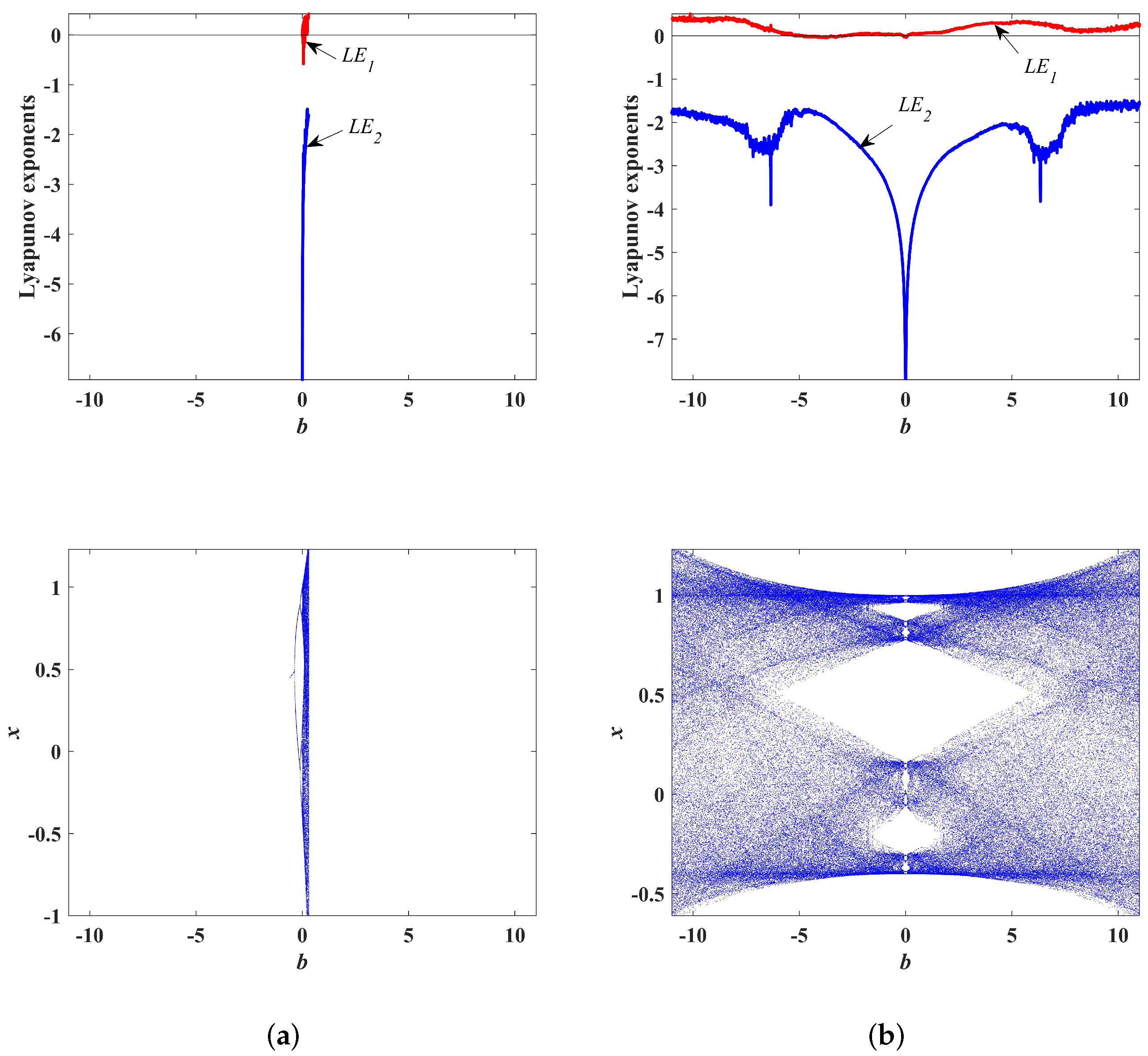
Fixed , LEs and its corresponding bifurcation diagrams of the Hénon map and DM-based Hénon map with are shown in Figure 14. The bifurcation diagram of the DM-based Hénon map is like the bifurcation diagram of the Hénon map stretched to the right. The chaotic region of the DM-based Hénon map is wider than that of Hénon map . The largest of the DM-based Hénon map is 0.6568 when , while that of the Hénon map is 0.4262 when . Fixed , LEs, and the corresponding bifurcation diagrams of the Hénon map and the DM-based Hénon map with are shown in Figure 15. In Figure 15, it is obvious that the chaos region of the DM-based Hénon map is much wider than that of Hénon map . Therefore, the introduction of discrete memristors to the Hénon map expands the chaotic parameters region and improves the dynamical complexity of the system.
To study the effect of system initials on the system state, the dynamical maps described by the LE on plane of the DM-based Hénon map with , , , and Hénon map with are plotted in Figure 16. It is worth noting that the chaos region of DM-based Hénon map is extra wide while the chaos region of the Hénon map is just a little colorful part in Figure 16a. The white-colored part in Figure 16b means the LE is the null value because of the divergent sequence. In Figure 16b, the dynamical map is distributed in vertical stripes, which means the change in causes almost no change in LE value. In terms of LE value, the LE values of both maps are just slight fluctuations with different initials, indicating that the system initials in the chaos region do not effectively increase the complexity of the system. However, this demonstrates that the discrete memristor can effectively expand the initial space of the chaotic map.
To study the effect of the memristor initial and parameter to system state, set , , , the dynamical map described by the LE on the plane of DM-based Hénon map is exhibited in Figure 17. It is worth noting that the chaos region in plane is also extra wide, which is very suitable for the communication security field.
To summarize the above experiments, the range of parameter values for the DM-based Hénon map and the original Hénon map are shown in Table 2.
4.4. Complexity Analysis
The permutation entropy of DM-based Hénon map (, , and Hénon map () for is plotted in Figure 18. In Figure 18b, the valid values of PE for the DM-based Logistic map cover almost the whole coordinate area, while there is a large invalid region in Figure 18a. The the color, the higher the complexity. As can be observed, the color of Figure 18a is also lighter than that of Figure 18b, indicating that the DM-based Hénon map is more complex than the original Hénon map. The highest PE value of the DM-based Hénon map is 0.8646 at and , while that of the original Hénon map is only 0.6209. Therefore, the discrete memristor not only improves the complexity of the Hénon map but also expands the effective region.
5. Conclusions
In this paper, two discrete memristors were designed based on the discrete model. The Simulink models of these two discrete memristors were constructed to prove that they satisfy the three fingerprints of the memristor. As their applications, a discrete memristor-based Logistic map and discrete memristor-based map were designed based on the original chaotic map and discrete memristor. To prove the feasibility of these two DM-based chaotic maps, we built Simulink models of them. The dynamic behaviors of these two DM-based chaotic maps were investigated through trajectory analysis, Lyapunov exponent, bifurcation diagram, and complexity analysis. The simulation results showed that the parameter space and the initial space of the DM-based chaotic map were much wider than that of the original map. It is worth mentioning that the initial space of the Henon map changed from finite to infinite due to the introduction of the discrete memristor. Moreover, the complexity of the DM-based chaotic map is higher and wider than that of the original map. Therefore, the discrete memristor indeed improves the dynamic behavior of the chaotic map, making the chaotic map more suitable for secure communication fields. In future work, we will study the applications of discrete memristors in digital circuits and discrete systems.
Author Contributions
G.L. and H.Z. wrote the manuscript; W.X. and X.X. performed the literature review; and H.Z. submitted the manuscript to the journal. All authors have read and agreed to the published version of the manuscript.
Funding
This research was funded by Natural Science Foundation of Guangxi province of Guodong Li (The image encryption model design based on cellular neural network and generalized chaotic synchronization theory), Guilin University of Electronic Technology Fund of Guodong Li grant number No. C21YJM00QX99, the Innovation Project of GUET Graduate Education of Huiyan Zhong grant number No. 2021YCXS119 and No. 2022YCX139 and supported by the Key Laboratory of Data Analysis and Computation in Universities in Guangxi Autonomous Region and the Guangxi Center for Applied Mathematics (Guilin University of Electronic Science and Technology).
Institutional Review Board Statement
Not applicable.
Informed Consent Statement
Not applicable.
Data Availability Statement
Not applicable.
Conflicts of Interest
The authors declare that this research was conducted in the absence of any commercial or financial relationships that may be construed as a potential conflict of interest.
References
- Chua, L.O. The Fourth Element. Proc. IEEE 2012, 100, 1920–1927. [Google Scholar] [CrossRef]
- Chua, L.O. Memristor-The missing circuit element. IEEE Trans. Circuit Theory 1971, 18, 507–519. [Google Scholar] [CrossRef]
- Strukov, D.B.; Snider, G.S.; Stewart, D.R.; Williams, R.S. The missing memristor found. Nature 2008, 453, 80–83. [Google Scholar] [CrossRef] [PubMed]
- Maikap, S.; Banerjee, W. In Quest of Nonfilamentary Switching: A Synergistic Approach of Dual Nanostructure Engineering to Improve the Variability and Reliability of Resistive Random-Access-Memory Devices. Adv. Electron. Mater. 2020, 6, 2000209. [Google Scholar] [CrossRef]
- Banerjee, W. Challenges and Applications of Emerging Nonvolatile Memory Devices. Electronics 2020, 9, 1029. [Google Scholar] [CrossRef]
- Banerjee, W.; Kim, S.H.; Lee, S.; Lee, S.; Lee, D.; Hwang, H. Deep Insight into Steep-Slope Threshold Switching with Record Selectivity (>4 × 10¹⁰) Controlled by Metal-Ion Movement through Vacancy-Induced-Percolation Path: Quantum-Level Control of Hybrid-Filament. Adv. Funct. Mater. 2021, 31, 2104054. [Google Scholar] [CrossRef]
- Cagli, C.; Ielmini, D.; Nardi, F.; Lacaita, A.L. Evidence for threshold switching in the set process of NiO-based RRAM and physical modeling for set, reset, retention and disturb prediction. In Proceedings of the 2008 IEEE International Electron Devices Meeting, San Francisco, CA, USA, 15–17 December 2008; pp. 1–4. [Google Scholar] [CrossRef]
- Alayan, M.; Vianello, E.; Navarro, G.; Carabasse, C.; La Barbera, S.; Verdy, A.; Castellani, N.; Levisse, A.; Molas, G.; Grenouillet, L.; et al. In-depth investigation of programming and reading operations in RRAM cells integrated with Ovonic Threshold Switching (OTS) selectors. In Proceedings of the 2017 IEEE International Electron Devices Meeting (IEDM), San Francisco, CA, USA, 2–6 December 2017; pp. 2.3.1–2.3.4. [Google Scholar] [CrossRef]
- Sun, Y.; Song, C.; Yin, S.; Qiao, L.; Wan, Q.; Wang, R.; Zeng, F.; Pan, F. Design of a Controllable Redox-Diffusive Threshold Switching Memristor. Adv. Electron. Mater. 2020, 6, 2000695. [Google Scholar] [CrossRef]
- Yao, P.; Wu, H.; Gao, B.; Tang, J.; Zhang, Q.; Zhang, W.; Yang, J.J.; Qian, H. Fully hardware-implemented memristor convolutional neural network. Nature 2020, 577, 641–646. [Google Scholar] [CrossRef]
- Wen, S.; Wei, H.; Yan, Z.; Guo, Z.; Yang, Y.; Huang, T.; Chen, Y. Memristor-Based Design of Sparse Compact Convolutional Neural Network. IEEE Trans. Netw. Sci. Eng. 2020, 7, 1431–1440. [Google Scholar] [CrossRef]
- Cai, F.; Kumar, S.; Van Vaerenbergh, T.; Sheng, X.; Liu, R.; Li, C.; Liu, Z.; Foltin, M.; Yu, S.; Xia, Q.; et al. Power-efficient combinatorial optimization using intrinsic noise in memristor Hopfield neural networks. Nat. Electron. 2020, 3, 409–418. [Google Scholar] [CrossRef]
- Cai, F.; Correll, J.M.; Lee, S.H.; Lim, Y.; Bothra, V.; Zhang, Z.; Flynn, M.P.; Lu, W.D. A fully integrated reprogrammable memristor—CMOS system for efficient multiply-accumulate operations. Nat. Electron. 2019, 2, 290–299. [Google Scholar] [CrossRef]
- Yoon, J.H.; Zhang, J.; Lin, P.; Upadhyay, N.; Yan, P.; Liu, Y.; Xia, Q.; Yang, J.J. A Low-Current and Analog Memristor with Ru as Mobile Species. Adv. Mater. 2020, 32, e1904599. [Google Scholar] [CrossRef] [PubMed]
- Zhang, Y.; Ping, Y.; Zhang, Z.; Zhao, G. Recent Advances in Dimensionality Reduction Modeling and Multistability Reconstitution of Memristive Circuit. Complex 2021, 2021, 2747174:1–2747174:18. [Google Scholar] [CrossRef]
- Dai, W.; Xu, X.; Song, X.; Li, G. Audio Encryption Algorithm Based on Chen Memristor Chaotic System. Symmetry 2022, 14, 17. [Google Scholar] [CrossRef]
- Xu, X.; Li, G.; Dai, W.; Song, X. Multi-Direction Chain and Grid Chaotic System based on Julia Fractal. Fractals 2021, 29, 2150245-141. [Google Scholar] [CrossRef]
- Song, X.; Xu, D.; Li, G.; Xu, W. Multi-image Reorganization Encryption Based on S-L-F Cascade Chaos and Bit Scrambling. J. Web Eng. 2021, 20, 1115–1130. [Google Scholar] [CrossRef]
- Zhong, H.; Li, G. Multi-image encryption algorithm based on wavelet transform and 3D shuffling scrambling. Multimed. Tools Appl. 2022. [Google Scholar] [CrossRef]
- Li, G.; Xu, X.; Zhong, H. TA image encryption algorithm based on coexisting multi-attractors in a spherical chaotic system. Multimed. Tools Appl. 2022. [Google Scholar] [CrossRef]
- Corinto, F.; Forti, M. Memristor circuits: Bifurcations without parameters. IEEE Trans. Circuits Syst. I Reg. Pap. 2017, 64, 1540–1551. [Google Scholar] [CrossRef]
- Itoh, M.; Chua, L.O. Memristor oscillators. Int. J. Bifurc. Chaos 2008, 18, 3183–3206. [Google Scholar] [CrossRef]
- Bao, H.; Jiang, T.; Chu, K.; Chen, M.; Xu, Q.; Bao, B. Memristor based canonical Chua’s circuit: Extreme metastability in voltage-current domain and its controllability in flux charge domain. Complexity 2018, 2018, 5935637. [Google Scholar] [CrossRef] [Green Version]
- Bao, B.; Jiang, T.; Wang, G.; Jin, P.; Bao, H.; Chen, M. Two-memristor-based Chua’s hyperchaotic circuit with plane equilibrium and its extreme multistability. Nonlinear Dyn. 2017, 89, 1157–1171. [Google Scholar] [CrossRef]
- He, S.; Sun, K.; Peng, Y.; Wang, L. Modeling of discrete fracmemristor and its application. Aip Adv. 2020, 10, 015332. [Google Scholar] [CrossRef]
- Bao, B.; Li, H.; Wu, H.; Zhang, X.; Chen, M. Hyperchaos in a second-order discrete memristor-based map model. Electron. Lett. 2020, 56, 769–770. [Google Scholar] [CrossRef]
- Bao, H.; Hua, Z.; Li, H.; Chen, M.; Bao, B. Discrete Memristor Hyperchaotic Maps. IEEE Trans. Circuits Syst. Regul. Pap. 2021, 68, 4534–4544. [Google Scholar] [CrossRef]
- Peng, Y.; He, S.; Sun, K. Chaos in the discrete memristor-based system with fractional-order difference. Results Phys. 2021, 24, 104106. [Google Scholar] [CrossRef]
- Fu, L.; He, S.; Wang, H.; Sun, K. Simulink modeling and dynamic characteristics of discrete memristor chaotic system. Acta Phys. Sin. 2022. [Google Scholar] [CrossRef]
- Adhikari, S.P.; Sah, M.P.; Kim, H.; Chua, L.O. Three Fingerprints of Memristor. IEEE Trans. Circuits Syst. Regul. Pap. 2013, 60, 3008–3021. [Google Scholar] [CrossRef]
- May, R.M. Simple mathematical models with very complicated dynamics. Nature 1976, 261, 459–467. [Google Scholar] [CrossRef]
- Wolf, A.; Swift, J.; Swinney, H.; Vastano, J.A. Determining Lyapunov exponents from a time series. Phys. Nonlinear Phenom. 1985, 16, 285–317. [Google Scholar] [CrossRef] [Green Version]
- Pajevic, S. Nonlinear dynamics and chaos. J. Stat. Phys. 1995, 78, 1635–1636. [Google Scholar] [CrossRef]
- Lai, D.; Chen, G. Statistical analysis of Lyapunov exponents from time series: A Jacobian approach. Math. Comput. Model. 1998, 27, 1–9. [Google Scholar] [CrossRef]
- Bandt, C.; Pompe, B. Permutation entropy: A natural complexity measure for time series. Phys. Rev. Lett. 2002, 88, 174102. [Google Scholar] [CrossRef] [PubMed]
- Hénon, M. Numerical study of quadratic area-preserving mappings. Q. Appl. Math. 1969, 27, 291–312. [Google Scholar] [CrossRef] [Green Version]
- Hénon, M. A two-dimensional mapping with a strange attractor. Commun. Math. Phys. 1976, 50, 69–77. [Google Scholar] [CrossRef]
- Benedicks, M.; Carleson, L. The Dynamics of the Hénon Map. Ann. Math. 1991, 133, 73–169. [Google Scholar] [CrossRef]
Figure 1.
Simulink model of discrete memristor.

Figure 2.
Current–voltage characteristic curves of discrete memristor Equation (6) with: (a) and ; (b) and .
Figure 2.
Current–voltage characteristic curves of discrete memristor Equation (6) with: (a) and ; (b) and .

Figure 3.
Current–voltage characteristic curves of discrete memristor Equation (6) with: (a) and ; (b) and .
Figure 3.
Current–voltage characteristic curves of discrete memristor Equation (6) with: (a) and ; (b) and .

Figure 4.
Simulink model of DM-based Logistic map.

Figure 5.
Simulink simulation trajectory of: (a) DM-based Logistic map for a = 2.9; (b) DM-based Logistic map for and ; (c) Logistic map for and .
Figure 5.
Simulink simulation trajectory of: (a) DM-based Logistic map for a = 2.9; (b) DM-based Logistic map for and ; (c) Logistic map for and .

Figure 6.
Simulink simulation 3D phase plane of: (a) DM-based Logistic map for ; (b) Logistic map for .
Figure 6.
Simulink simulation 3D phase plane of: (a) DM-based Logistic map for ; (b) Logistic map for .

Figure 7.
LEs and BD relying on system parameter a for of: (a) Logistic map with ; (b) DM-based Logistic map with , , .
Figure 7.
LEs and BD relying on system parameter a for of: (a) Logistic map with ; (b) DM-based Logistic map with , , .

Figure 8.
LEs and BDs relying on system initial for of: (a) Logistic map with ; (b) DM-based Logistic map with , , .
Figure 8.
LEs and BDs relying on system initial for of: (a) Logistic map with ; (b) DM-based Logistic map with , , .

Figure 9.
LEs and BDs relying on memristor initial of DM-based Logistic map for , . (a) LEs; (b) BD.
Figure 9.
LEs and BDs relying on memristor initial of DM-based Logistic map for , . (a) LEs; (b) BD.

Figure 10.
LEs and BD relying on memristor parameter k of DM-based Logistic map for . (a) LEs; (b) BD.
Figure 10.
LEs and BD relying on memristor parameter k of DM-based Logistic map for . (a) LEs; (b) BD.

Figure 11.
The permutation entropy of DM-based Logistic map () and Logistic map () for .

Figure 12.
Simulink model of discrete memristor-based Hénon map.

Figure 13.
Simulink simulation chaotic attractor of DM-based Hénon map with (a) , ; (b) and , .

Figure 14.
LEs and BDs relying on system initial a for of: (a) Hénon map with ; (b) DM-based Hénon map with , , , .
Figure 14.
LEs and BDs relying on system initial a for of: (a) Hénon map with ; (b) DM-based Hénon map with , , , .

Figure 15.
LEs and BDs relying on system initial b for of: (a) Hénon map with , ; (b) DM-based Hénon map with , , , .
Figure 15.
LEs and BDs relying on system initial b for of: (a) Hénon map with , ; (b) DM-based Hénon map with , , , .

Figure 16.
Dynamical map described by the LE on - plane (a) Hénon map with ; (b) DM-based Hénon map with .
Figure 16.
Dynamical map described by the LE on - plane (a) Hénon map with ; (b) DM-based Hénon map with .

Figure 17.
Dynamical map described by the LE on k- plane of DM-based Hénon map with .

Figure 18.
The permutation entropy for of: (a) Hénon map ; (b) DM-based Hénon map .


Table 1.
Chaos region of DM-based Logistic map and Logistic map.
| Chaos Region | DM-Based Logistic Map (Condition) | Logistic Map (Condition) |
|---|---|---|
| a | [−2.99, −2.31] ∪ [2.31, 3] () | [−2, −1.57] ∪ [3.57, 4] () |
| [−1.16, 0) ∪ (0, 1.16] () | [0.01, 0.99] (a = 4) | |
| [0,1.52] () | - | |
| k | [0,0.1] () | - |
Table 2.
Chaos region of DM-based Hénon map and Hénon map.
| Chaos Region | DM-Based Hénon Map (Condition) | Hénon Map (Condition) |
|---|---|---|
| a | [1.4,1.993] (, , , ) | (, ) |
| b | [−10.89,11] (, , , ) | [0,0.3] (, ) |
(, , , ) | (, ) | |
(, , ) | - |
Publisher’s Note: MDPI stays neutral with regard to jurisdictional claims in published maps and institutional affiliations. |
© 2022 by the authors. Licensee MDPI, Basel, Switzerland. This article is an open access article distributed under the terms and conditions of the Creative Commons Attribution (CC BY) license (https://creativecommons.org/licenses/by/4.0/).
Share and Cite
MDPI and ACS Style
Li, G.; Zhong, H.; Xu, W.; Xu, X. Two Modified Chaotic Maps Based on Discrete Memristor Model. Symmetry 2022, 14, 800. https://doi.org/10.3390/sym14040800
AMA Style
Li G, Zhong H, Xu W, Xu X. Two Modified Chaotic Maps Based on Discrete Memristor Model. Symmetry. 2022; 14(4):800. https://doi.org/10.3390/sym14040800
Chicago/Turabian StyleLi, Guodong, Huiyan Zhong, Wenxia Xu, and Xiangliang Xu. 2022. "Two Modified Chaotic Maps Based on Discrete Memristor Model" Symmetry 14, no. 4: 800. https://doi.org/10.3390/sym14040800
Note that from the first issue of 2016, this journal uses article numbers instead of page numbers. See further details here.