1. Introduction
Recent design developments in membrane gas separation are moving this technology towards being economically competitive for post-combustion carbon capture from coal-fired power stations [
1,
2]. Here these competitive membrane process designs are extended to post-combustion capture from a Natural Gas Combined Cycle (NGCC) process, to evaluate the viability of membrane technology.
Traditionally, membrane-based carbon capture has only been considered for natural gas sweetening before NGCC [
3] and for pre-combustion capture before the IGCC process [
4], while post-combustion capture has only been studied in depth using solvent absorption [
5,
6,
7,
8,
9], or as a novel Integrated Gasification Combined Cycle (IGCC) process with flue gas recycling [
10]. This is because for NGCC the flue gas has a low CO
2 partial pressure which has previously been seen as a limitation for membrane gas separation. Belaissaoui
et al. [
11] recently proposed overcoming this for membrane systems through flue gas recycle, where some of the CO
2 produced is recycled through the gas turbine resulting in a higher CO
2 partial pressure. Similar flue gas recycle has been proposed for solvent absorption technology for NGCC [
12]. For coal post-combustion, flue gas recycling has been shown by Merkel
et al. [
2] to make membrane separation viable for post-combustion capture from a coal-fired power station. In that case, the process consists of three CO
2-selective membrane stages with a cryogenic liquefaction process for CO
2 separation. Sweep gas on the second membrane stage is designed to recycle CO
2 through the coal burner, and importantly enable the entire membrane process to operate at low pressure. This differs from Belaissaoui
et al. process, which requires compression before the membrane stage. The three stages membrane process is able to recover over 90% of the CO
2 and achieves a product purity of over 95% CO
2 at a cost of capture comparable with current state-of-art solvent absorption technology. Hence, the three membrane stage combination presents itself as the current state of the art membrane process for post-combustion capture. As such, the three membrane stages design is applied here to post-combustion carbon capture from a NGCC process. This differs from Belaissaoui
et al. design, in that the process presented here operates at low pressures.
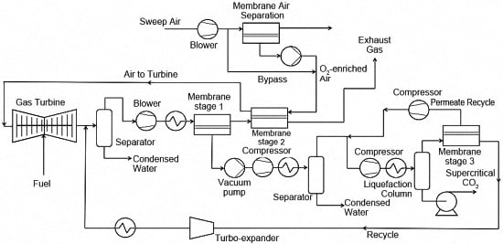
The capture design utilises two CO
2-selective membrane stages in series to concentrate CO
2 in the permeate stream of the first membrane stage, and uses the second membrane stage to recycle CO
2 back through the turbine (
Figure 1). The CO
2 rich permeate from the first membrane stage then undergoes water removal followed by compression and liquefaction to produce CO
2 at the necessary purity. The membrane stages minimise the energy requirements of the liquefaction process by the exclusion of N
2. The second membrane stage processes the retentate from the first membrane stage, and recycles CO
2 back to the process feed stream through the turbine. This is possible because the combustion air for the turbine is used as a sweep gas on the second membrane stage. Combustion air as the sweep gas is a critical feature of the design to generate the pressure driving force across the membrane in order to maximise CO
2 recovery while minimising membrane area and energy duty. However, recycling CO
2 through the turbine (known as exhaust gas recirculation (EGR)) can result in limitations to the overall efficiency because of flame stability issues, incomplete oxidation of CO and changes to convection thermal transfer [
13]. The third CO
2-selective membrane stage recovers CO
2 from the liquefaction column off-gas and recycles the permeate stream back to the first membrane stage permeate stream. The retentate from the third membrane stage is recycled back to the first membrane stage feed stream. This ensures all the CO
2 around the liquefaction process is recovered while minimising the cooling duty.
The recycling of CO
2 through the turbine also has the problem of reducing the O
2 partial pressure in the combustion zone, and hence reduces the efficiency of the turbine because of incomplete combustion. Therefore, in this paper we have introduced a fourth O
2-enrichment membrane stage on the combustion air upstream of the second membrane stage to counter the problem of reduced O
2 partial pressure. This increases the O
2 concentration of combustion air/sweep gas and ensures the correct O
2 partial pressure is present in the gas turbine, as well as lowering N
2 concentration to ensure the volumetric flowrate is similar to that of the non-EGR NGCC process. Substituting CO
2 for N
2 in the process will impact blade cooling, convection transfer and Heat Recovery Steam Generator (HRSG) operations [
14]. However, the concept of O
2 enrichment of the combustion air has previously been considered for oxy-fuel NGCC capture and is likely to be applicable in this configuration [
10].
To enable comparison with other carbon capture technologies, economic analysis of the carbon capture options is also presented [
15].
3. Results and Discussion
The combination of two membrane stages with CO
2 recycle through the turbine overcomes the limitation experienced with only one membrane stage; that is choosing between recovery or purity in the permeate stream. The two CO
2-selective membrane stages in series on the flue gas feed enables both high CO
2 recovery and high CO
2 purity to be achieved in the permeate stream of the first membrane stage. This ensures that N
2 is excluded from the liquefaction process and reduces the subsequent compression and cooling duty. In a NGCC power plant with capture, an important parameter in the design is the amount of CO
2 being recycled through the turbine, via the combustion air sweep gas. This is varied by alternating the relative CO
2 recovery in the first and second membrane stages, while always ensuring that the combined CO
2 recovery is greater than 90%. The amount of CO
2 being recycled through the turbine in this analysis is varied between 2.5% and 30%, with literature suggesting the impact from the higher recycle level, while significant, is within operational conditions of gas turbines [
22]. Where a small recovery in the first membrane stage results in a significant amount of CO
2 being recycled via the second membrane stage and vice versa. Importantly, the two stage membrane process ensures that the CO
2 purity in the first stage permeate stream is always above 75%, irrespective of the individual membrane stage recoveries.
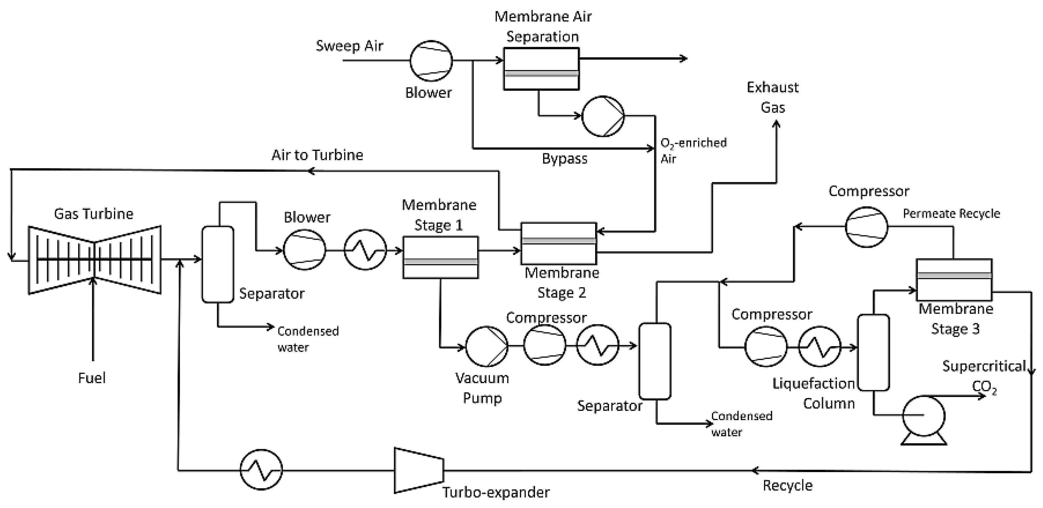
Altering the amount of CO
2 being recycled through the process impacts the equipment size and energy duty. A large CO
2 recycle reduces the membrane area for both the first and second membrane stages, because of the higher partial pressure. However, a large recycle rate also increases the energy duty of the process as the feed blower must handle increased throughput. This represents a trade-off between equipment cost through reduced membrane area and increased energy duty. The impact CO
2 recycle has on cost of capture is shown in
Figure 2. The NGCC process achieves a minimum in the cost of capture when the CO
2 recycle going through the turbine is 0.25 mole fraction for NGCC. At lower CO
2 recycle rates, the membrane area of the first and second stages are substantially large because the CO
2 partial pressure is low, producing only a small driving force for separation. This resulted in a substantial CAPEX due to significant increases in membrane cost as well as OPEX increase because of higher membrane replacement cost. In contrast, at higher CO
2 recycle of 0.3, there is a smaller membrane area, but the increase in energy demand of the feed blower, and a significant increase in OPEX offsets any reduction in membrane CAPEX. In terms of the gas turbine, operating the NGCC process with the combustion air having a CO
2 mole fraction of 0.24 is theoretically possible. However, industrial testing will be required to demonstrate its feasibility.
For the NGCC scenario where the recycle rate is 0.24, the combined CO
2-selective membrane area is 3.3 × 10
5 m
2, which is comparable with existing natural gas sweetening membrane areas [
3]. Of the CO
2-selective membranes, the total area is mostly associated with the second membrane stage, given the high CO
2 recycle through the turbine, while the third membrane stage area is less than 100 m
2 to recycle the small amount of CO
2 in the off-gas from the liquefaction process and the first membrane requires an area of about 1.6 × 10
4 m
2. In comparison the O
2-enrichment process membrane area is 7.9 × 10
5 m
2. This area is more than double that of the CO
2-selective membranes, and indicates the quantity of air for combustion needed to be processed to ensure the correct O
2 partial pressure in the turbines.
As shown in
Figure 2, the cost of post-combustion capture for a NGCC power plant with a combined three-CO
2 selective membrane process and O
2-enrichment membrane has a minimum capture cost of US$91 per tonne of CO
2 avoided. This cost is greater than values reported for post-combustion NGCC capture using solvent technology. For a Fluor solvent the cost of capture is US$58 per tonne of CO
2 avoided, and with a MHI solvent the cost of capture is US$48 per tonne of CO
2 avoided [
23]. The corresponding energy penalties for these processes are about 15% and 11% respectively. It should be noted that these costs are for a 776 MW NGCC process with the same operating lifetime and load factor, but a higher COE at $0.067/kWh. As such, the results suggest that the membrane process does not compete with solvent technology for NGCC. Furthermore, the cost for the proposed post-combustion NGCC membrane process has been shown to be lower if used at a supercritical coal-fired power station, with reported values of US$28–US$32 per tonne of CO
2 avoided [
24]. One of the main reasons for the difference in cost is the lower CO
2 purity in the liquefaction process, 0.75 for the post-combustion NGCC compared to 0.9 CO
2 mole fraction in the coal-fired power station process. This increases the energy duty for the vacuum pump, compressor and cooling. For the NGCC process the energy demand is 35% (117 MW). Hence, over a third of the power output from the power plant is consumed by the capture plant, whilst for the coal power plant it was less than 30%.
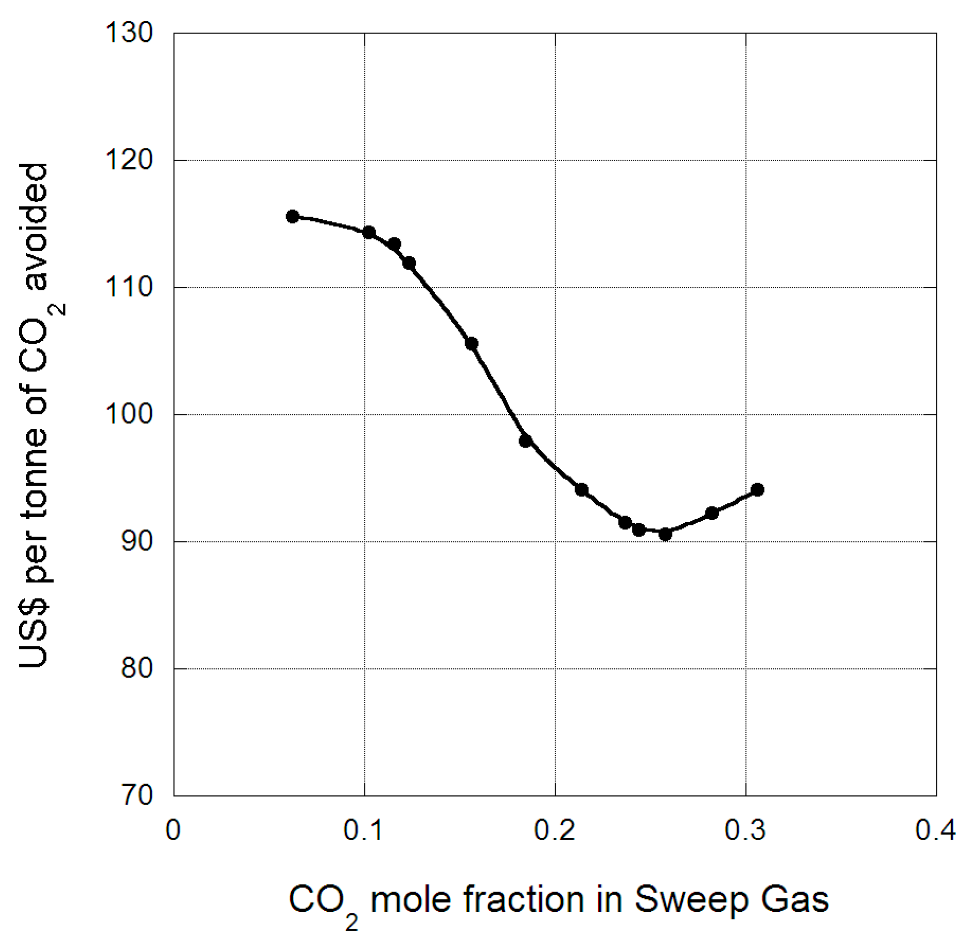
The breakdown of the energy duty for the capture plant is provided in
Figure 3. The feed blower accounts for almost half of the energy duty of the capture plant. This unit operation is a blower, not a compressor, as it provides the necessary pressure (150 kPa) for the flue gas to pass through membrane stages 1 and 2. The significant energy duty is because of the large amount of CO
2 recycle and considerable gas throughput in the process. The next major component, accounting for over a quarter of the energy demand is the vacuum pump on the first membrane stage to ensure sufficient partial pressure driving force across the membrane module. Hence, gas handling accounts for three quarters or more of the energy demand of this capture process, and highlights the major limitation of achieving significant energy savings for membrane processes with low CO
2 partial pressure systems. The refrigeration cooling duty in the liquefaction process accounts for 19%.
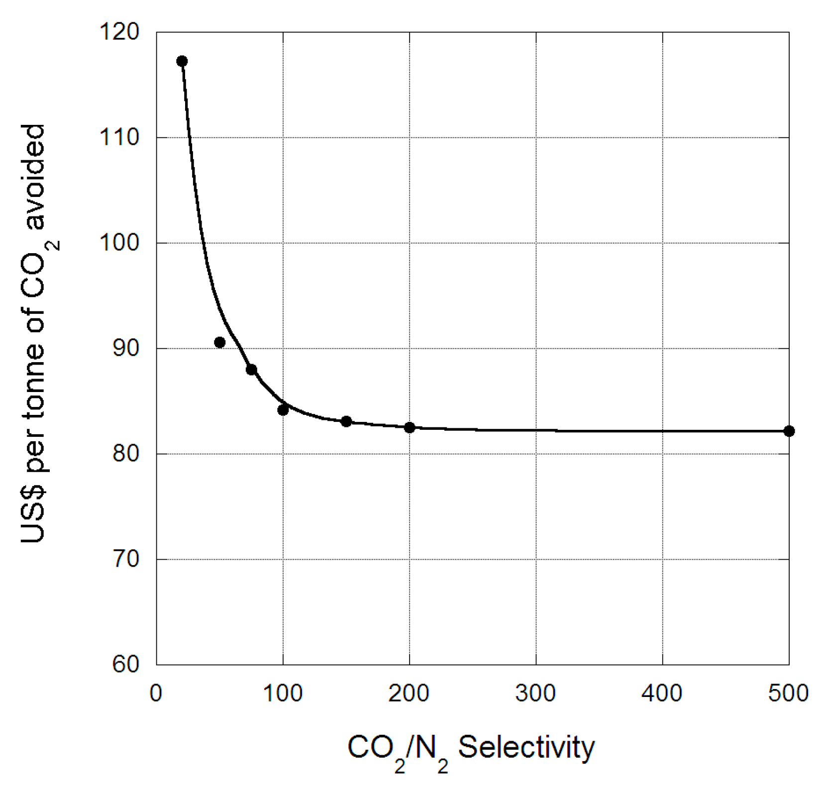
The CO
2/N
2 selectivity is a major membrane variable as it controls the purity of CO
2 entering the liquefaction process. Improving the selectivity reduces both the compression and cooling duty of the process, because of exclusion of N
2 from the liquefaction process. This represents a reduction in cost of capture, as shown in
Figure 4 for the NGCC process. The cost of capture falls as selectivity increases and reaches a plateau at CO
2/N
2 = 150. Above this selectivity there is no savings made in the cost of capture because essentially enough of the N
2 has been excluded from the permeate stream in the first membrane stage to meet the required CO
2 concentration for storage, once water has been removed. At this selectivity, the cost of capture reduces to about US$83 per tonne of CO
2 avoided, though it is still higher than conventional solvent technology. However, while a number of polymeric membrane materials have reported selectivities this high [
25], to the authors’ knowledge none have been commercialized. One of the current best performing membrane for post-combustion capture is MTR’s Polaris, which has a CO
2/N
2 selectivity of 50 [
2]. Hence, to obtain these potential decreases in cost of capture, further development of membrane materials and improvement in selectivity will be required.
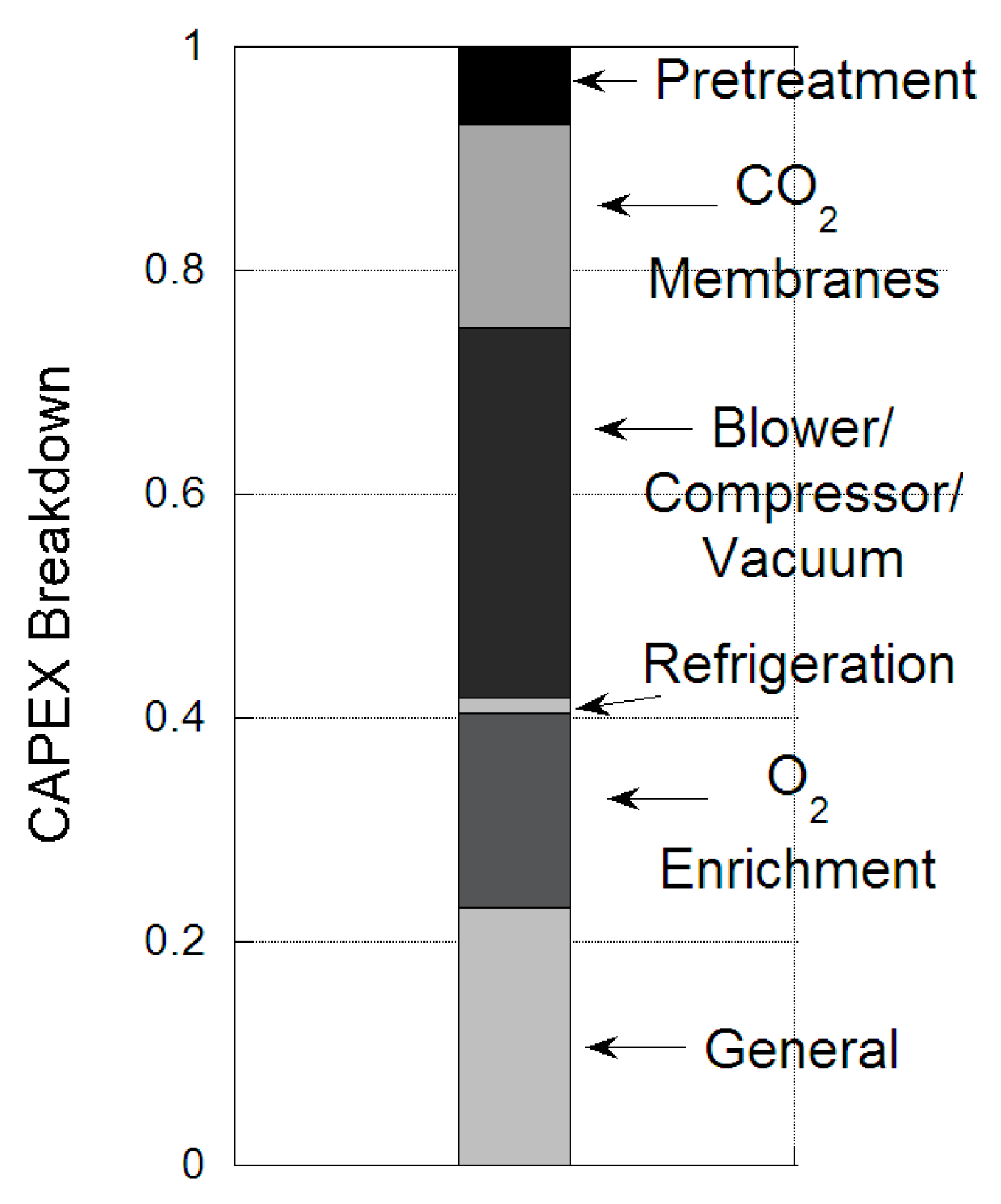
The CAPEX breakdown of the capture plant is provided in
Figure 5. The biggest capital expense is the blower/compressor/vacuum pump for gas handling. The next biggest expense is the general cost, of piping, instrumentation,
etc. The CO
2-selective membranes contribute 18% to the CAPEX. Hence, to achieve a CAPEX reduction, savings must be made to the gas handling equipment, in particular the feed blower which accounts for 26% of the CAPEX.
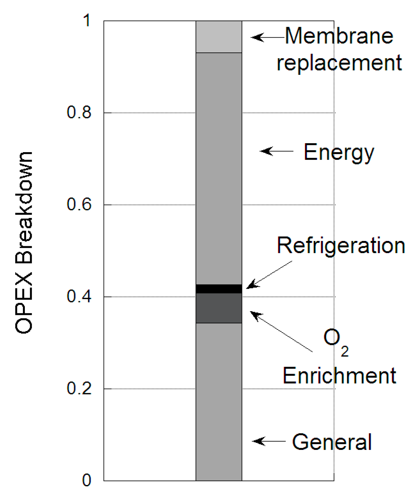
The OPEX breakdown is provided in
Figure 6. Again, the biggest contribution is the energy cost for gas handling, account for 50%. The next largest contributor to the OPEX is the general cost, including cooling water and plant maintenance. The refrigeration duty is 3% of the OPEX, O
2 enrichment process is 7%, because of the high air throughput, while membrane replacement is less than 7%.
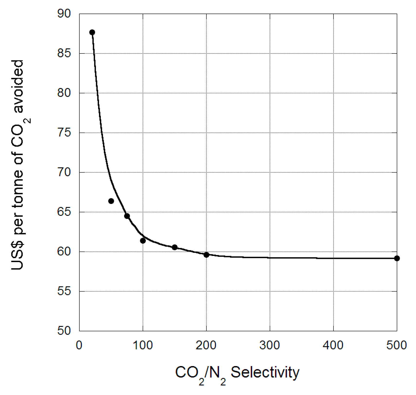
One option to reduce the cost of capture could be to eliminate the feed blower from the process, given that it accounts for almost half the energy duty of the process because of the high gas throughput. This will require the exhaust gas from the Heat Recovery Steam Generator (HRSG) to be at sufficient pressure to ensure flow through the associated duct work. However, reducing the HRSG back pressure results in a reduction to the power output and efficiency of the combined cycle, ~0.25% loss per 50 mbar [
26]. Removing the blower and incorporating the power loss because of increased flue gas pressure, indicates that the energy demand for the membrane capture plant becomes 60 MW, and reduces the parasitic load on the NGCC plant to 20%. The cost of capture for the process without the feed blower is provided in
Figure 7, as a function of membrane CO
2/N
2 selectivity. At a CO
2/N
2 selectivity of 50, the cost of capture for NGCC reduces to US$67 per tonne of CO
2 avoided if the blower is excluded, which represents a saving of 26% compared to the baseline case. Again, the cost of capture reduces with increased selectivity until it reaches a constant value at CO
2/N
2 = 200, because of the high CO
2 purity in the permeate stream eliminates the need for liquefaction.


