


ABSTRACT
In order to investigate star-formation (SF) processes in extreme environments, we have carried out a multi-wavelength analysis of the mid-infrared bubble N46, which hosts a WN7 Wolf–Rayet (W–R) star. We have used 13CO line data to trace an expanding shell surrounding the W–R star containing about five condensations within the molecular cloud associated with the bubble. The W–R star is associated with a powerful stellar wind having a mechanical luminosity of ∼4 × 1037 erg s−1. A deviation of the H-band starlight mean polarization angles around the bubble has also been traced, indicating the impact of stellar wind on the surroundings. The Herschel temperature map shows a temperature range of ∼18–24 K toward the five molecular condensations. The photometric analysis reveals that these condensations are associated with the identified clusters of young stellar objects, revealing ongoing SF process. The densest among these five condensations (peak N(H2) ∼9.2 × 1022 cm−2 and AV ∼ 98 mag) is associated with a 6.7 GHz methanol maser, an infrared dark cloud, and the CO outflow, tracing active massive SF within it. At least five compact radio sources (CRSs) are physically linked with the edges of the bubble, and each of them is consistent with the radio spectral class of a B0V–B0.5V-type star. The ages of the individual infrared counterparts of three CRSs (∼1–2 Myr) and a typical age of WN7 W–R star (∼4 Myr) indicate that the SF activities around the bubble are influenced by the feedback of the W–R star.
Export citation and abstract BibTeX RIS
1. INTRODUCTION
Massive stars (≳8 M⊙) have a significant impact on their surroundings through feedback mechanisms such as ionizing radiation, stellar winds, and radiation pressure. The Wolf−Rayet (W–R) stars represent a late phase in the evolution of O stars and can significantly influence the local neighborhood through the kinetic energy contained in their very powerful winds (Lamers & Cassinelli 1999). In recent years, infrared emission at the Spitzer 8 μm band has been used to reveal thousands of bubble-/shell-like structures toward the Galactic star-forming regions (Churchwell et al. 2006, 2007; Simpson et al. 2012). Such features often surround the OB stars (including W–R stars), indirectly illustrating their origin due to the energetics of powering source(s). Such sites have gained considerable interest for exploring the interaction between massive stars and their surroundings (e.g., Deharveng et al. 2010). Massive stars can stimulate the birth of young stars. The feedback of massive stars can also disrupt the parental molecular cloud and thus halt the star-formation (SF) process. Together, massive stars can have constructive and destructive effects on their neighborhoods. Therefore, the knowledge of physical conditions in such sites can allow us to understand the star birth process in extreme environments (e.g., regions around OB stars and H ii regions), as well as to infer the predominant feedback mechanism of massive stars. Such investigation will enable us to observationally assess the available various theoretical processes "collect and collapse" (see Elmegreen & Lada 1977; Whitworth et al. 1994; Dale et al. 2007), "radiation-driven implosion" (see Bertoldi 1989; Lefloch & Lazareff 1994), and the radiation-magnetohydrodynamic simulations of the expansion of the H ii region around an O star in a turbulent magnetized molecular cloud (Arthur et al. 2011).
The mid-infrared (MIR) bubble, N46 (Churchwell et al. 2006), contains a spectroscopically identified W–R 1503-160L star (subtype WN7; Shara et al. 2012) and is a poorly studied region. The bubble N46 (l = 27 31; b = −011) is referred to as a broken or incomplete ring with an average radius (diameter) and thickness of 1
 38 (276) and 048 (Churchwell et al. 2006), respectively. The bubble N46 is associated with an H ii region, G027.3−00.1 (Lockman 1989; Beaumont & Williams 2010). The line of sight velocity of the molecular gas (∼92.6 km s−1; Beaumont & Williams 2010) is consistent with the velocity of the ionized gas (∼92.3 km s−1; recombination line width ∼32.7 km s−1; Lockman 1989) toward the bubble N46, suggesting the physical association of the molecular and ionized emissions. Beaumont & Williams (2010) utilized the CO (J = 3–2) line data around this bubble and estimated a near kinematic distance of 4.8 ± 1.4 kpc, which is adopted throughout the present work.
The detailed and careful investigation of an individual hosting site of the W–R star will allow us to explore the SF process in extreme environments. Despite the presence of the W–R 1503-160L star in the bubble N46, the physical conditions around the bubble have yet to be explored. The impact of the energetics of the W–R 1503-160L star on its local environment is not known. In this paper, we examine the distribution of dust temperature, column density, extinction, ionized emission, kinematics of molecular gas, distribution of magnetic field lines, and young stellar objects (YSOs) around the bubble, using the multi-wavelength data spanning from the centimeter wave band to the near-infrared (NIR).
In Section 2, we describe the multi-wavelength data sets adopted in this work. Section 3 deals with the physical environment around the bubble. This section also provides the details of the photometric analysis of point-like sources. In Section 4, we discuss possible SF scenarios to explain the presence of young stars around the bubble. A summary of conclusions is given in Section 5.
2. DATA AND ANALYSIS
In the present work, we selected a region of ∼24' × 133 (central coordinates: l = 273228; b = −01437) around the bubble N46.
2.1. New Observations
2.1.1. Optical Spectrum
Optical spectrum of the W–R 1503-160L star (l = 272987; b = −01207) was obtained on 2015 April 12 using the Himalaya Faint Object Spectrograph and Camera (HFOSC) mounted on the 2 m Himalayan Chandra Telescope (HCT). The spectrum was observed using grism 8 (5800–8350 Å; R ∼ 2190) of the HFOSC with an exposure time of 30 minutes. A few bias frames and Fe–Ne calibration lamp spectra were also taken for the bias subtraction and calibration of the observed spectrum. Following the standard reduction procedures, the observed optical spectrum was extracted using a semi-automated pipeline written in PyRAF (Ninan et al. 2014; Baug et al. 2015). The signal-to-noise ratio (S/N) of the optical spectrum is found to be 45.
2.1.2. Near-infrared Spectra
The NIR H- and K-band spectra of the W–R star were also observed on 2015 April 13 using the TIFR Near Infrared Spectrometer and Imager (TIRSPEC; Ninan et al. 2014) mounted on the HCT. Spectra were obtained at two dithered positions with an effective on-source integration time of 300 and 600 s at the H and K bands, respectively. TIRSPEC has an average spectral resolution of ∼1200. Several continuum and Argon lamp spectra were also obtained for the continuum subtraction and wavelength calibration of the observed spectra. A separate telluric standard (α Aql) was also observed for telluric correction. Adopting the standard reduction procedures, the observed spectra were reduced using a semi-automated pipeline written in PyRAF (Ninan et al. 2014; Baug et al. 2015). Finally, the reduced spectra at the H and K bands were flux-calibrated using the Two Micron All Sky Survey (2MASS; resolution ∼2 5; Skrutskie et al. 2006) photometry of the W–R star. The S/N of our observed H- and K-band spectra is obtained to be 20 and 45, respectively.
2.2. Archival Data
To study the SF process, we used multi-wavelength observations from various Galactic plane surveys (e.g., the Multi-Array Galactic Plane Imaging Survey (MAGPIS; λ = 20 cm; Helfand et al. 2006), the Galactic Ring Survey (GRS; λ = 2.7 mm; Jackson et al. 2006), the Bolocam Galactic Plane Survey (BGPS; λ = 1.1 mm; Ginsburg et al. 2013), the APEX Telescope Large Area Survey of the Galaxy (ATLASGAL; λ = 870 μm; Schuller et al. 2009), the Herschel Infrared Galactic Plane Survey (Hi-GAL; λ = 70, 160, 250, 350, 500 μm; Molinari et al. 2010), the MIPS Inner Galactic Plane Survey (MIPSGAL; λ = 24 μm; Carey et al. 2005), the Wide Field Infrared Survey Explorer (WISE; λ = 12 μm; Wright et al. 2010), the Galactic Legacy Infrared Mid-Plane Survey Extraordinaire (GLIMPSE; λ = 3.6, 4.5, 5.8, 8 μm; Benjamin et al. 2003), the UKIRT NIR Galactic Plane Survey (GPS; λ = 1.25, 1.65, 2.2 μm; Lawrence et al. 2007), the Galactic Plane Infrared Polarization Survey (GPIPS; λ = 1.6 μm; Clemens et al. 2012), and 2MASS (λ = 1.25, 1.65, 2.2 μm)). In the following sections, we give a brief description of these archival data.
2.2.1. NIR Data
We extracted deep NIR photometric JHK magnitudes of point sources in our selected region from the UKIDSS GPS sixth archival data release (UKIDSSDR6plus). UKIDSS observations (resolution ∼08) were taken using the UKIRT Wide Field Camera (WFCAM; Casali et al. 2007). The final fluxes were calibrated using the 2MASS data. One can also obtain more information about the selection procedure of the GPS photometry in Dewangan et al. (2015a). Our selected GPS catalog consists of sources fainter than J = 12.0, H = 11.2, and K = 10.0 mag to avoid saturation. 2MASS data were obtained for bright sources that were saturated in the GPS catalog.
2.2.2. H-band Polarimetry
NIR H-band (1.6 μm) polarimetric data (resolution ∼15) were downloaded from the GPIPS. The data were collected with the Mimir instrument on the 1.8 m Perkins telescope in H-band linear imaging polarimetry mode (see Clemens et al. 2012 for more details).
2.3. Spitzer Data
We obtained photometric images and magnitudes of point sources in our selected region from the Spitzer-GLIMPSE survey at 3.6–8.0 μm (resolution ∼2''). The data were retrieved from the GLIMPSE-I spring 2007 highly reliable catalog. The image at MIPSGAL 24 μm was collected. We also used MIPSGAL 24 μm photometry (from Gutermuth & Heyer 2015) in this work.
2.4. Herschel, ATLASGAL, and BGPS Data
Herschel far-infrared and sub-millimeter (sub-mm) continuum maps at 70, 160, 250, 350, and 500 μm were obtained from the Herschel data archive. The beam sizes of these images are 58, 12'', 18'', 25'', and 37'' (Griffin et al. 2010; Poglitsch et al. 2010), respectively. The processed level2−5 products were downloaded using the Herschel Interactive Processing Environment (HIPE; Ott 2010).
The sub-mm continuum map at 870 μm (beam size ∼192) was retrieved from the ATLASGAL. A Bolocam 1.1 mm image was also obtained from the BGPS. The beam size of the 1.1 mm map is ∼33''.
2.5. 13CO (J = 1−0) Line Data
The 13CO (J = 1−0) line data were obtained from the GRS. The GRS data have a velocity resolution of 0.21 km s−1, an angular resolution of 45'' with 22'' sampling, a main beam efficiency (ηmb) of ∼0.48, a velocity coverage of −5 to 135 km s−1, and a typical rms sensitivity (1σ) of ≈0.13 K (Jackson et al. 2006).
2.6. Radio Centimeter Continuum Map
Radio continuum map at 20 cm was extracted from the VLA MAGPIS. The map has a 62 × 54 beam and a pixel scale of 2'' pixel−1.
3. RESULTS
3.1. Optical and NIR Spectra of the W–R 1503-160L
Spectroscopic observations offer a unique opportunity to characterize the individual astronomical objects. In Figure 1, we present optical (5500–9200 Å) and NIR H- and K-band spectra of the W–R 1503-160L star. The optical and NIR spectra mainly show the broad emission lines of ionized helium and nitrogen, confirming it as a W–R star. In general, due to the strong stellar wind of a W–R star, the outer hydrogen envelopes are thrown away and thus strong lines of He and other heavy elements (N, O, C) are observed in the spectra of W–R stars. In the present work, we have utilized both optical and NIR spectra to determine the spectral type of this source. Smith et al. (1996) have demonstrated a classification scheme of W–R stars using the helium lines (He ii at 4686 and 5411 Å, and He i at 5875 Å) in the optical spectrum. Figer et al. (1997) have also shown that several characteristic lines in the NIR K-band spectrum can be used to determine the spectral subtype of a W–R star. Our optical spectrum does not cover the lines in the blue part, as used by Smith et al. (1996), hence, we primarily carried out the identification of the spectral type using our K-band spectrum. The absence of carbon lines and the presence of highly ionized nitrogen lines in all the spectra preliminarily confirm the source as a nitrogen-rich W–R star (e.g., WN subtype; see Table 1). From our observed K-band spectrum, the equivalent widths of the 2.112 μm (He i + N iii), 2.166 μm (H i + He i + He ii), and 2.189 (He ii) lines were calculated by fitting Gaussian profiles (see Table 1). Good agreement of the ratio of equivalent widths (2.189/2.112 ∼ 0.85 and 2.189/2.166 ∼ 0.72) corresponding to the WN7 star, as reported in Figure 1 of Figer et al. (1997), confirms the source as a WN7-type star. Furthermore, we have compared the ratio of equivalent widths of several optical lines with those values reported in Conti et al. (1990). The ratios of the equivalent widths of He i 6678 Å and He ii 8237 Å (ratio ∼1.27), and He i 6678 Å and blended He i 7065 Å + N iv 7715 Å (ratio ∼0.37) agree well with the values reported for several WN7 stars (e.g., WR 55, WR 120, WR 148, and WR 158) in Conti et al. (1990). Hence, from our observed optical and NIR spectra, we confirm the source as a WN7 W–R star. Note that the source was previously characterized as a WN7 W–R-type star using the K-band spectrum (with a spectral resolution of ∼1200) by Shara et al. (2012). Our K-band spectrum (with a spectral resolution of ∼1000) is similar to the spectrum reported in Shara et al. (2012). Similar characteristics of broad emission lines of He and N are seen in the present study as well as previously published work. We have given equivalent widths of our observed lines in Table 1, which are consistent with the NIR lines listed in Table 5 in Shara et al. (2012). They utilized the 2MASS colors of the source and estimated an extinction to be∼0.84 mag in the Ks band. They also computed a distance to the W–R 1503-160L star of ∼3.1 kpc, assuming it is a strong-lined WN7 star.
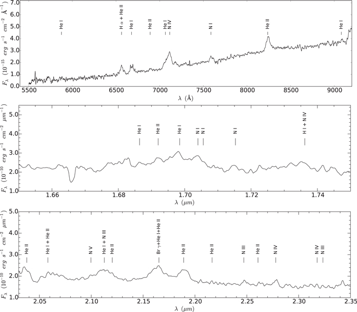
Figure 1. Optical (top panel), H-band (middle panel), and K-band (bottom panel) spectra of the W–R 1503-160L star (l = 272987; b = −01207; the location of the W–R star is shown in Figure 2; see the text). The broad emission lines of ionized helium and nitrogen are seen (also see Table 1).
Download figure:
Standard image High-resolution imageTable 1. Equivalent Width Measurements
| Lines | Wavelength (μm) | Equivalent Width (Å) |
|---|---|---|
| He ii | 0.6660 | −37.2 |
| He i | 0.6678 | −28.8 |
| He i | 0.7065 | −78.0 |
| N i | 0.7587 | −10.9 |
| N iii | 0.8236 | −18.0 |
| He ii | 1.6920 | −39.3 |
| He i | 1.6990 | −21.5 |
| He i | 2.0610 | −29.0 |
| He i + N iii | 2.1120 | −49.9 |
| He i a | 2.1656 | −58.7 |
| He ii a | 2.1890 | −42.2 |
Note.
aThese lines are blended. So their equivalent width values can be taken as indicative numbers.Download table as: ASCIITypeset image
In this work, we have also utilized the widths of lines seen in our observed spectra and have estimated the terminal velocity of the emitting gas of the W–R star. In the first step, we determined the instrumental broadening of the lines using the isolated observed sky emission lines, which is found to be ∼430 km s−1. Furthermore, the equivalent widths of the He ii+ Hα line at 6563 Å and the Brγ + He i + He ii line at 2.166 μm were used to determine the velocity of the expanding gas. Finally, after correcting the velocity for the instrumental broadening, we obtain the terminal velocity of the outflowing gas to be ∼1600 ± 400 km s−1.
Crowther et al. (2006) extensively studied the properties of W–R stars in a super cluster, Westerlund 1, and suggested a criterion to infer the strong-lined and weak-lined WN7 W–R stars. They mentioned that the strong-lined WN7 W–R stars have FWHMs of the He ii 2.1885 μm line of ≥130 Å. They also listed the absolute magnitudes of strong-lined and weak-lined WN7 W–R stars, which are different for these two subclasses. The absolute magnitudes (in the Ks band) of strong-lined and weak-lined WN7 W–R stars were reported to be −4.77 mag and −5.92 mag, respectively (see Table A1 in Crowther et al. 2006), which will lead two different estimates of distance. Taking into account these absolute magnitudes along with 2MASS photometry (m = 8.51 mag) and extinction (A
 ∼0.84 mag; as mentioned above) in the Ks band, we compute the distances to strong-lined and weak-lined WN7 W–R 1503-160L stars of 3.1 ± 0.7 kpc and 5.2 ± 0.7 kpc, respectively. Using our K-band spectra, the FWHM of the He ii 2.1885 μm line of W–R 1503-160L is about 110 Å, which implies the source to be a weak-lined WN7 star. Considering this result and our calculations, we adpot the distance to the weak-lined WN7 W–R star of 5.2 ± 0.7 kpc, which is in good agreement with the kinematic distance of the bubble N46. Hence, taken together, we suggest that the bubble N46 hosts the W–R 1503-160L star.
3.2. Physical Environment Around the Bubble N46
The knowledge of the ionized, dust, and molecular emissions in a given star-forming complex allows us to infer physical conditions, and to provide details about H ii regions, possible outflows, and photon-dominated regions. Additionally, the distribution of molecular gas in a given star-forming region also helps us to trace its exact physical extension/boundary.
3.2.1. Global View
In Figure 2, we show the spatial distribution of ionized emission, warm dust emission, and molecular gas around the bubble N46. Figure 2(a) is a three-color composite image made using MAGPIS 20 cm in red, Herschel 70 μm in green, and GLIMPSE 8.0 μm in blue. The radio continuum map at MAGPIS 20 cm reveals several ionized regions. The image at 70 μm represents the warm dust emission, whereas the 8 μm band is dominated by the 7.7 and 8.6 μm polycyclic aromatic hydrocarbon (PAH) emission (including the continuum). In Figure 2(b), we show the molecular 13CO (J = 1–0) gas emission in the direction of the bubble N46. The 13CO profile depicts the bubble region in a velocity range of 87–100 km s−1. The supernova remnant (SNR) G027.3+00.0 (also known as Kes 73) is seen as the most prominent ionized region in the radio map (see Figure 2(a)). The radio map also traces some compact point-like radio sources. The composite map also displays the edges of the bubble as a prominent bright feature coincident with the 20 cm emission (see Figure 2(a)). In Figure 2(a), we have marked the positions of some known astronomical objects (see Table 2 for coordinates), which are seen in the global view of the bubble N46. As mentioned before, the bubble harbors the WN7 W–R 1503-160L star that is situated at a projected linear separation of ∼867 from the SNR G027.3+00.0. Ferrand & Safi-Harb (2012) tabulated the distance and age of SNR G027.3+00.0 to be 7.5–9.1 kpc and 750–2100 years, respectively. Using photometric and spectroscopic analyses (as mentioned earlier), we find the distance of the W–R 1503-160L star to be 5.2 ± 0.7 kpc, which is consistent with the distance of the bubble (i.e., 4.8 ± 1.4 kpc). In general, W–R stars have very high mass-loss rates ((2–5) × 10−5 M⊙ yr−1) with terminal velocities of 1000–2500 km s−1 (Prinja et al. 1990) and have lifetimes of roughly a few million years (Lamers & Cassinelli 1999). Considering the distance of the bubble N46, these two sources, SNR G027.3+00.0 and bubble N46, do not appear to be physically linked. Therefore, the impact of SNR G027.3+00.0 on the surroundings of the bubble N46 is unlikely.
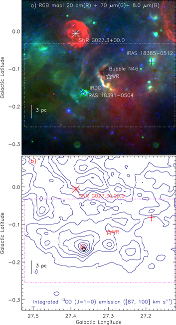
Figure 2. Global view of the region around the bubble N46 (size of the selected field ∼246 × 246; central coordinates: l = 273260; b = −01236). (a) The image is the result of the combination of three bands (in linear scale): 20 cm in red (MAGPIS), 70 μm in green (Herschel), and 8.0 μm in blue (Spitzer). The color composite map depicts the ionized emission (in 20 cm map), warm dust emission (in 70 μm image), and PAH emission including the continuum (in 8 μm image). (b) Molecular 13CO gas in the direction of the bubble N46. The CO integrated velocity range is from 87 to 100 km s−1. The CO contours are 45.27 K km s−1 × (0.1, 0.2, 0.3, 0.4, 0.55, 0.7, 0.85, 0.95). In both panels, the positions of IRAS 18385−0512 (+), IRAS 18391−0504 (×), SNR G027.3+00.0 (∗), a 6.7 GHz methanol maser emission  , and the W–R 1503-160L star (⋆) are marked. The scale bar corresponding to 3 pc at a kinematical distance of 4.8 kpc is shown in both panels. In both panels, the dotted–dashed box shows the field of Figure 4.
Download figure:
Standard image High-resolution imageTable 2. Coordinates of Some Referred Astronomical Objects Seen in a Global View of the Bubble N46, as Marked in Figures 2 and 3
| ID | Galactic | Galactic | R.A. | decl. |
|---|---|---|---|---|
| Longitude (degree) | Latitude (degree) | [J2000] | [J2000] | |
| Bubble N46 | 27.3100 | −0.1100 | 18:41:33.0 | −05:03:07.6 |
| W–R 1503-160L | 27.2987 | −0.1207 | 18:41:34.1 | −05:04:01.2 |
| IRAS 18385−0512 | 27.1853 | −0.0822 | 18:41:13.3 | −05:09:01.1 |
| IRAS 18391−0504 | 27.3689 | −0.1598 | 18:41:50.2 | −05:01:21.0 |
| SNR G027.3+00.0 | 27.3866 | −0.0060 | 18:41:19.2 | −04:56:11.0 |
| IRDC (SDC G27.356−0.152) | 27.3568 | −0.1530 | 18:41:47.4 | −05:01:48.5 |
| 6.7 GHz methanol maser | 27.3650 | −0.1660 | 18:41:51.0 | −05:01:42.8 |
| N46clm | 27.2940 | −0.1540 | 18:41:40.7 | −05:05:11.0 |
| clm1 | 27.4653 | −0.1510 | 18:41:58.9 | −04:55:58.0 |
| clm2 | 27.2418 | −0.1751 | 18:41:39.5 | −05:08:33.0 |
| clm3 | 27.4653 | −0.1510 | 18:41:23.3 | −05:04:59.2 |
Download table as: ASCIITypeset image
3.2.2. Local Environment
In Figure 2(b), based on the distribution of molecular emission, we have selected the region around the bubble for our present study, where a majority of molecular gas is distributed (hereafter, N46 molecular cloud; see the dotted–dashed box in Figure 2(b)). In Figure 3, we show the multi-wavelength images of the selected region around the bubble N46 at 12, 160, 250, 350, 500, 1100 μm, integrated 13CO emission, and 20 cm. The radio continuum and integrated CO maps are also shown for comparison with the infrared and sub-mm images. The details of the integrated CO map as well as the kinematics of molecular gas are given in Section 3.3. We have highlighted the positions of IRAS 18385−0512, IRAS 18391−0504, 6.7 GHz methanol maser emission (MME), and the W–R star. The WISE 12 μm band traces the warm dust emission and contains the PAH emission feature at 11.3 μm. The 160–1100 μm images indicate the presence of the cold dust emission (see Section 3.4 for quantitative estimates). We identify about five molecular condensations (e.g., clm1, clm2, clm3, MME, and N46clm) based on visual inspection of the integrated molecular map, which are labeled in the map. The MME condensation is found to be associated with an infrared dark cloud (IRDC) in the 8 μm image. The IRDC appears as a bright in emission at wavelengths longer than 24 μm. In Figure 4(a), we show a color composite image made using 8 μm (blue), 24 μm (green), and 70 μm (red) images. In Figure 4(a), the inset on the bottom right shows the zoomed in view toward the MME and IRAS 18391−0504 (a color composite image: 5.8 μm (red), 4.5 μm (green), and 3.6 μm (blue) images). The observed MME is located ∼253 away from IRAS 18391−0504 (see the inset in Figure 4(a)). In Figures 4(b) and (c), we present the zoomed in view of the bubble N46, which depict the edges of the bubble. Figure 4(c) shows the absence of radio continuum peak toward the W–R star located inside the bubble. Note that the 20 cm continuum emission is lacking inside the bubble except a detection of a point-like radio source. Additionally, the 24 μm emission, which traces the warm dust emission, is not enclosed by the 8 μm emission. It indicates that the bubble structure is unlikely to be originated by the expanding H ii region.
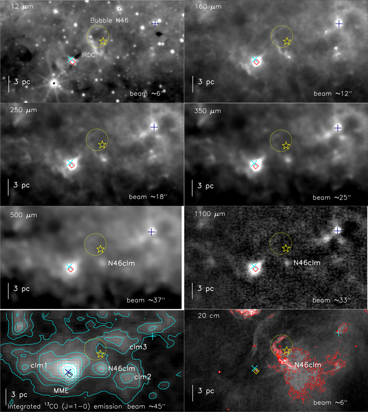
Figure 3. Distribution of warm dust, cold dust, molecular gas, and ionized emissions in the region around the bubble N46, using the WISE, Herschel, BOLOCAM, GRS, and MAGPIS surveys. The selected area (size of the region ∼24' × 133; central coordinates: l = 273228; b = −01437) is shown by a dotted–dashed box in Figure 2(a). The panels display images at 12, 160, 250, 350, 500, 1100 μm, integrated 13CO emission, and 20 cm, from left to right in increasing order. The CO emission is also shown by cyan contours with 45.18 K km s−1 × (0.1, 0.2, 0.3, 0.4, 0.55, 0.7, 0.85, 0.95). In the integrated CO map, some noticeable peak positions (i.e., clm1, clm2, clm3, MME, and N46clm) are labeled. The MAGPIS 20 cm emission is also overlaid by red solid contours with levels of 0.0023, 0.0035, 0.0046, 0.0064, 0.0081, 0.0099, and 0.011 Jy/beam. In all the panels, the other marked symbols are similar to those shown in Figure 2. The position of the W–R 1503-160L star (⋆) is marked in all panels. In all panels, a big circle indicates the location of the bubble N46 (with a diameter of ∼276 or 3.85 pc at a distance of 4.8 kpc), as reported by Churchwell et al. (2006).
Download figure:
Standard image High-resolution image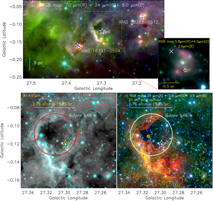
Figure 4. (a) Composite color image (70 μm (red), 24 μm (green), and 8.0 μm (blue); in log scale) of the region around the bubble N46. The selected area is shown by a dotted–dashed box in Figure 2(a). The inset on the bottom right represents the IRAS 18391−0504 region in zoomed in view, using a three-color composite image made of three Spitzer images (5.8 μm (red), 4.5 μm (green), and 3.6 μm (blue)) in log scale (see the solid red box in figure). A small white circle represents the peak position of the 5 GHz detection in the inset panel. The highlighted dotted–dashed box in figure shows the field of Figures 4(b) and (c). (b) A zoomed in view of the bubble N46 using Spitzer8 μm grayscale image (in log scale). The 8 μm contours are also overlaid with levels of 1.46, 1.65, 1.7, 1.8, 1.9, 2.0, and 2.1 MJy/sr (in log scale). (c) A close up view of the bubble N46 using three Spitzer images (24 μm (red), 5.8 μm (green), and 3.6 μm (blue); in log scale). The MAGPIS 20 cm contours in yellow are similar to those shown in Figure 3. The compact radio sources (CRSs) are highlighted by numbers in blue color (also see Table 3). In the last two panels, a thick big circle shows the location of the bubble N46. In all the panels, the other marked symbols are similar to those shown in Figure 2.
Download figure:
Standard image High-resolution imageShirley et al. (2013) reported the molecular HCO+ (3–2) gas velocities to be ∼91.1 and ∼89.2 km s−1 toward the N46clm and clm1 condensations, respectively. The peak velocity of 6.7 GHz MME is ∼99.7 km s−1 (Szymczak et al. 2012). Ammonia (NH3) line observations were also reported toward MME condensation by Wienen et al. (2012). They found the radial velocities of the NH3 gas to be between 91.21 and 91.70 km s−1 and also estimated the near kinematic distance as 5.06 kpc. However, the line of sight velocity of molecular gas toward IRAS 18385−0512 is ∼26 km s−1 (Sridharan et al. 2002). With knowledge of these velocities, it appears that the bubble N46, the W–R star, and five condensations (including IRAS 18391−0504 and 6.7 GHz MME) belong to the same region (see Figure 4(b)); however, IRAS 18385−0512 is not physically associated with the N46 molecular cloud. Considering this fact, we do not discuss the results related to IRAS 18385−0512 in the present work.
All together, with the help of molecular line data and the distribution of cold, warm, and ionized emission, we find the physical association of the W–R star and molecular condensations located inside the N46 molecular cloud. Furthermore, the ionized emission appears to be well correlated with the warm dust emission at the edges of the bubble.
3.2.3. Compact Radio Sources
In Figure 4(c), the radio peaks (or compact radio source, CRS) are seen toward the edges of the bubble and are designated by numbers as 1–10 (see also Table 3). In this section, the number of Lyman continuum photon (Nuv) is computed for each CRS using the integrated flux density following the equation of Matsakis et al. (1976; see Dewangan et al. 2015b for more details). We used the "CLUMPFIND" IDL program (Williams et al. 1994) to obtain the integrated flux density for each CRS. The calculations were performed for a distance of 4.8 kpc and for the electron temperature of 10,000 K. The values of integrated flux density and Nuv are listed in Table 3. The table also contains the spectral class of each of the CRSs (see Table 1 in Smith et al. 2002 for theoretical values). Each CRS appears to be associated with a single ionizing star of spectral type B0V/B0.5V (see Table 3).
Table 3. Physical Parameters of the CRSs Seen on the Edges of the Bubble (See Figure 4(c))
| ID | Galactic | Galactic | R.A. | decl. | Total Flux | log Nuv | Spectral Type |
|---|---|---|---|---|---|---|---|
| Longitude (degree) | Latitude (degree) | [J2000] | [J2000] | (Sν in Jy) | (s−1) | ||
| CRS1 | 27.3162 | −0.1349 | 18:41:39.0 | −05:03:28.8 | 0.1960 | 47.55 | B0V–O9V |
| CRS2 | 27.3128 | −0.1454 | 18:41:40.9 | −05:03:56.9 | 0.1430 | 47.42 | B0V |
| CRS3 | 27.3139 | −0.1121 | 18:41:33.9 | −05:02:58.4 | 0.0137 | 46.40 | B1V |
| CRS4 | 27.3023 | −0.1404 | 18:41:38.7 | −05:04:22.4 | 0.2254 | 47.61 | B0V–O9V |
| CRS5 | 27.3067 | −0.1476 | 18:41:40.7 | −05:04:20.1 | 0.1538 | 47.45 | B0V |
| CRS6 | 27.3184 | −0.1232 | 18:41:36.8 | −05:03:02.5 | 0.0892 | 47.21 | B0.5V–B0V |
| CRS7a | 27.3250 | −0.1204 | 18:41:36.9 | −05:02:36.6 | 0.0794 | 47.16 | B0.5V–B0V |
| CRS8 | 27.3128 | −0.1238 | 18:41:36.3 | −05:03:21.2 | 0.0941 | 47.23 | B0.5V–B0V |
| CRS9a | 27.3100 | −0.0949 | 18:41:29.8 | −05:02:42.5 | 0.1166 | 47.33 | B0.5V–B0V |
| CRS10a | 27.3278 | −0.1132 | 18:41:35.7 | −05:02:15.8 | 0.0774 | 47.15 | B0.5V–B0V |
Note.
aThe radio sources that are associated with the infrared counterparts.Download table as: ASCIITypeset image
3.2.4. Infrared Counterpart of CRSs and MME
In Figure 4(c), we have examined the infrared counterpart (IRc) of each CRS (within a radius of 4'' of the radio peak) via a visual inspection of GLIMPSE images. We find the IRcs of CRS7 (designated as G027.3235−00.1212), CRS9 (designated as G027.3115−00.0948), and CRS10 (designated as G027.3255−00.1109). The analysis of the NIR color–magnitude diagram also suggests these sources as massive stars earlier than spectral-type B0 (see Section 3.5.3 for spectral energy distribution (SED) modeling).
Additionally, we identify the embedded sources G027.2942−00.1559, G027.4598−00.1509, and G027.3650−00.1656 toward the peaks of N46clm, clm1, and MME condensations, respectively. The source G027.2942−00.1559 is detected at wavelengths longer than 2.2 μm, whereas the source G027.4598−00.1509 is seen only at wavelengths longer than 3.6 μm. We find an IRc of 6.7 GHz MME within a radius of 4'', which is designated as G027.3650−00.1656 in the GLIMPSE catalog and has GLIMPSE 4.5 and 5.8 μm band photometries (m4.5 = 10.07 ± 0.3 mag and m5.8 = 8.35 ± 0.2 mag). Purcell et al. (2013) reported the Coordinated Radio and Infrared Survey for High-Mass Star Formation (Hoare et al. 2012) 5 GHz (beam ∼15) radio source (i.e., G027.3644−00.1657; angular scale ∼17) close to this IRc (separation of ∼21; see the inset panel in Figure 4(a)). They also estimated the integrated flux density equal to 60.14 mJy, which refers to log(Nuv) of ∼47.0 s−1 and corresponds to a single powering star of radio spectral class B0.5V. A compact point-like radio continuum source at MAGPIS 20 cm is also detected toward the 6.7 GHz MME. In general, the detection of 6.7 GHz MME strongly indicates the presence of early phases of massive SF (MSF; e.g., Walsh et al. 1998; Urquhart et al. 2013).
In summary, the multi-wavelength images reveal the presence of MSF (B0V-type stars and 6.7 GHz MME) activities around the bubble.
3.3. Kinematics of Molecular Gas
This section deals with a kinematic analysis of the molecular gas in the N46 molecular cloud. The kinematics of the molecular gas may help us to explore the expansion of the bubble. Figure 5 shows the integrated GRS 13CO (J = 1−0) velocity channel maps (at intervals of 1 km s−1), revealing different molecular condensations along the line of sight. The channel maps show a clear separation of the high- and low-velocity emission toward the MME condensation. In the velocity range from 88 to 95 km s−1, the highlighted molecular condensations (i.e., clm1, clm2, clm3, MME, and N46clm) are well detected. Using GRS 13CO (J = 1−0) and radio continuum data, Anderson et al. (2009) examined the properties of the molecular cloud associated with the Galactic H ii regions including the bubble N46, which is referred to as C27.31−0.14 (Vlsr ∼ 92.3 km s−1) in their catalog. The integrated GRS 13CO intensity map5 was provided by these authors, however, the position–velocity analysis of this cloud is still lacking. In Figure 6, we present the integrated 13CO intensity map and the position–velocity maps. The galactic position–velocity diagrams of the 13CO emission reveals an almost inverted C-like structure as well as the presence of a noticeable velocity gradient toward the 6.7 GHz MME (see Figures 6(b) and (d)). In Figure 6(c), we show the bubble location traced at 8 μm along with the distribution of cold dust emission. As previously mentioned, the 6.7 GHz MME represents MSF and is associated with the densest clump in the N46 molecular cloud. Additionally, the MME condensation contains a cluster of young populations (see Section 3.5.2). The position–velocity diagrams convincingly suggest the presence of an outflow activity toward the MME condensation. In the channel maps, the orientations of the high- and low-velocity lobes appear significantly different (see the velocity range between 88 to 95 km s−1 in Figure 5). These features suggest the presence of multiple CO outflows in the MME condensation. We cannot further explore this aspect in this work due to the coarse beam of the GRS CO data (beam size 45''). The existence of an inverted C-like structure in the position–velocity plot often indicates an expanding shell (Arce et al. 2011). Arce et al. (2011) examined the observed molecular gas distribution in the Perseus molecular cloud along with a modeling of expanding bubbles in a turbulent medium. They indicated that the semi-ring-like or C-like structure in the position–velocity plot represents an expanding shell. The position of the W–R star is approximately situated at the center of the inverted C-like structure. Our position–velocity analysis indicates the presence of an expanding shell with an expansion velocity of the gas to be ∼3 km s−1.

Figure 5. 13CO(J = 1−0) velocity channel contour maps. The velocity value (in km s−1) is shown in each panel. The contour levels are 10%, 20%, 40%, 55%, 70%, 85%, and 98% of the peak value (in K km s−1), which is also indicated in each panel. Other marked symbols and labels are similar to those shown in Figure 3.
Download figure:
Standard image High-resolution image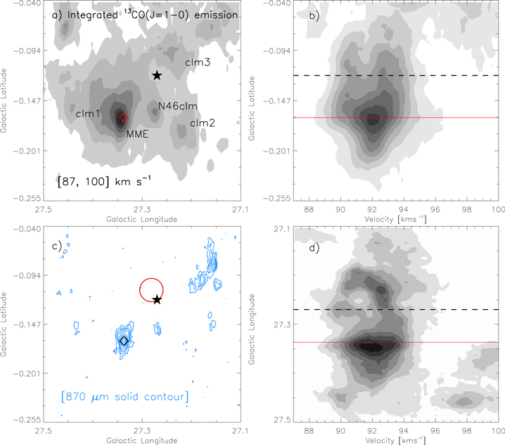
Figure 6. (a) Integrated intensity map of 13CO (J = 1–0). The map is similar to the one shown in Figure 3. (b) Latitude-velocity distribution of 13CO. The CO emission is integrated over the longitude from 271 to 275. (c) The ATLASGAL 870 μm contours (in dodger blue) are shown with levels of the 10.24 Jy/beam × (0.015, 0.03, 0.045, 0.08, 0.15, 0.25, 0.4, 0.7, and 0.98). The bubble location is similar to the one shown in Figure 4(b). (d) Longitude-velocity distribution of 13CO. The CO emission is integrated over the latitude from −004 to −0255. In both the left panels, the positions of the 6.7 GHz MME  and the W–R 1503-160L star (⋆) are marked. The solid red line and the dashed black line show the positions of the 6.7 GHz MME and the W–R 1503-160L star in the position–velocity maps, respectively. In panel (d), the plot depicts the inverted C-like morphology as well as a noticeable velocity gradient toward the 6.7 GHz MME (also see the text).
Download figure:
Standard image High-resolution imageTaken together, the CO kinematics suggest the presence of at least one outflow as well as the expanding shell.
3.4. Herschel Temperature and Column Density Maps
In this section, we study the distribution of column density, temperature, extinction, and clump mass in the N46 molecular cloud. We followed the procedures given in Mallick et al. (2015) to obtain the Herschel temperature and column density maps (see below). We obtained these maps from a pixel-by-pixel SED fit with a modified blackbody curve to the cold dust emission in the Herschel 160–500 μm wavelengths. The images at 250–500 μm are in the surface brightness unit of MJy sr−1, while the image at 160 μm is calibrated in the units of Jy pixel−1. The plate scales of the 160, 250, 350, and 500 μm images are 6.4, 6, 10, and 14 arcsec pixel−1, respectively.
Here, we provide a brief step-by-step description of the procedures. All images were first converted to Jy pixel−1 unit and were convolved to the angular resolution of 500 μm image (∼37'') using the convolution kernels available in the HIPE software. The images were regridded to the pixel size of a 500 μm image (∼14'') using the HIPE software. Next, the sky background flux level was measured to be 1.476, 3.705, 1.759, and 0.643 Jy pixel−1 for the 160, 250, 350, and 500 μm images (the size of the selected region ∼66 × 73; central coordinates: αJ2000 = 18h44m45s, δJ2000 = −05°40'00''), respectively. The featureless dark region far from the N46 molecular cloud, to avoid diffuse emission associated with target, was carefully chosen for the background estimation.
Finally, we fitted a modified blackbody to the observed fluxes on a pixel-by-pixel basis to obtain the maps (see Equations (8) and (9) given in Mallick et al. 2015). We performed the fitting using the four data points for each pixel, retaining the dust temperature (Td) and the column density (N(H2)) as free parameters. In the estimations, we used a mean molecular weight per hydrogen molecule (μH2=) 2.8 (Kauffmann et al. 2008) and an absorption coefficient (κν=) 0.1 (ν/1000 GHz)β cm2 g−1, including a gas-to-dust ratio (Rt=) of 100, with a dust spectral index of β = 2 (see Hildebrand 1983). In Figure 7, we show the final temperature and column density maps (resolution ∼37'') of our selected region around the bubble N46. In Figure 7(a), we find warmer gas (Td ∼ 23–27 K) toward the edges of the bubble. The Herschel temperature map also exhibits a temperature range of about 18–24 K toward the five molecular condensations as marked in Figure 3. We find the peak column densities of about 9.2 × 10²¹ (AV ∼ 10 mag), 6.31 × 10²¹ (AV ∼ 7 mag), 1.18 × 10²² (AV ∼ 12 mag), 9.2 × 10²² (AV ∼ 98 mag), and 9.17 × 10²¹ (AV ∼ 10 mag) cm−2 toward the molecular condensations clm1, clm2, clm3, MME, and N46clm, respectively (see Figure 7(b)). Here, we used the relation between optical extinction and hydrogen column density from Bohlin et al. (1978; i.e., AV = 1.07 × 10⁻²¹ N(H2)). Note that the clump associated with 6.7 GHz MME is relatively warmer (Td ∼ 24 K) and is the densest one compared to other condensations. Using NH3 line observations, Wienen et al. (2012) reported physical parameters of dense gas (i.e., the gas kinetic temperature and rotational temperature) toward the MME clump. The kinetic temperature of the MME clump was estimated to be ∼23.81 K, which is consistent with our estimated temperature value.
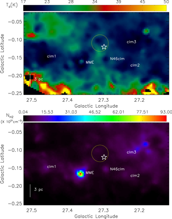
Figure 7. Herschel temperature map (top panel) and column density ( ) map (bottom panel) of our selected region around the bubble N46 (see the text for details). The extinction value can be inferred from the column density using the relation:
  . In the temperature map, the black area in a latitude range between −025 and −02 corresponds to NaN values. In both panels, the other marked symbols and labels are similar to those shown in Figure 3.
Download figure:
Standard image High-resolution imageWe estimate the masses of four prominent clumps (MME, N46clm, clm1, and clm2) seen in the column density map (see Figure 7(b)). The mass of a single clump can be obtained using the formula:

where  is assumed to be 2.8, Areapix is the area subtended by one pixel, and
  is the total column density. We employed the "CLUMPFIND" program to estimate the total column densities of the clumps. Using Equation (1), we compute the masses of the clumps MME, N46clm, clm1, and clm2 to be ∼7273, ∼954, ∼412, and ∼741 M⊙, respectively.
3.5. YSOs in the N46 Molecular Cloud
3.5.1. Selection of Infrared Excess Sources
The study of YSOs is considered a primary tracer of the star-formation activity in a given star-forming region. In the following, we use different photometric surveys to identify and classify YSOs.
- 1.We selected sources having detections in the MIPSGAL 24 μm and GLIMPSE 3.6 μm bands. The color–magnitude plot ([3.6]–[24]/[3.6]) has been utilized to trace the youngest population in a given star-forming region (Guieu et al. 2010; Rebull et al. 2011; Dewangan et al. 2015a). In our selected region, we find 135 sources that are common in the 3.6 and 24 μm bands. In Figure 8(a), we present the [3.6]–[24]/[3.6] plot of 135 sources. We select 32 YSOs (5 Class I; 2 Flat-spectrum; 25 Class II) and 103 Class III sources. The boundary of different stages of YSOs is also marked in Figure 8(a) (e.g., Guieu et al. 2010), which depicts the criteria to infer the youngest population. The figure also shows the boundary of possible contaminants (i.e., galaxies and disk-less stars; see Figure 10 in Rebull et al. 2011). We do not identify any contaminants (i.e., galaxies) in our selected YSOs.
- 2.We obtained sources having detections in all four GLIMPSE bands. Following the Gutermuth et al. (2009) schemes, we identified YSOs and various possible contaminants (e.g., broad-line active galactic nuclei (AGNs), PAH-emitting galaxies, shocked emission blobs/knots, and PAH-emission-contaminated apertures) in our selected region around the bubble. The possible contaminants are also removed from the selected YSOs. We further utilized the slopes of the Spitzer-GLIMPSE SED (
 ) measured from 3.6 to 8.0 μm (e.g., Lada et al. 2006) and classified the selected YSOs into different evolutionary stages (i.e., Class I (αIRAC > −0.3), Class II (−0.3 > αIRAC > −1.6), and Class III (−1.6 > αIRAC > −2.56)). One can also find more details of YSO classifications in Dewangan & Anandarao (2011, and references therein). In Figure 8(b), we show the GLIMPSE color–color diagram ([3.6]−[4.5] versus[5.8]−[8.0]) for all of the identified sources. In the end, we find 19 YSOs (3 Class I; 16 Class II), 2545 photospheres, 3 PAH-emitting galaxies, and 235 contaminants.
 - 3.Infrared excess traced in the first three GLIMPSE bands (except 8.0 μm band) can also offer to identify the additional protostars. The color–color space ([4.5]–[5.8] versus [3.6]–[4.5]) is utilized to trace the infrared excess sources. We use color conditions, [4.5]–[5.8] ≥ 0.7 and [3.6]–[4.5] ≥ 0.7, to select protostars, as given in Hartmann et al. (2005) and Getman et al. (2007). We identify four protostars in our selected region around the bubble (see Figure 8(c)).
- 4.The NIR H–K color excess also allows us to identify additional YSOs. In order to choose a color criterion, we examined the color–magnitude (H−K/K) plot of the nearby control field (size ∼6' × 6'; central coordinates: αJ2000 = 18h41m53
 6, δJ2000 = −05°14'555) and obtained a color H−K value (i.e., ∼2.0) that isolates large H−K excess sources from the rest of the population. Adopting this color H−K cut-off condition, we obtained 315 embedded YSOs in our selected region around the bubble (see Figure 8(d)).


Figure 8. Identification of a young stellar population within our selected region around the bubble N46 (see Figure 4). (a) Color–magnitude diagram ([3.6]−[24] vs. [3.6]) of sources observed in the IRAC and MIPSGAL bands (see the text for more details). The diagram allows us to distinguish YSOs belonging to different evolutionary stages (see the dashed lines). The dotted–dashed lines represent the separation chosen for YSOs against contaminated candidates (galaxies and disk-less stars; see Rebull et al. 2011, for more details). The " " and "
 " symbols represent the Flat-spectrum and Class III sources, respectively; (b) Color–color diagram ([3.6]−[4.5] vs. [5.8]−[8.0]) using the IRAC four-band detections. The "+" and "×" symbols represent the PAH-emitting galaxies and PAH-emission-contaminated apertures, respectively (see the text); (c) Color–color diagram ([3.6]−[4.5] vs. [4.5]−[5.8]) of the sources detected in three IRAC bands, except the 8.0 μm image; (d) Color–magnitude diagram (H−K/K) of the sources detected in the NIR bands. In all the panels, we show Class I (red circles) and Class II (open blue triangles) YSOs. In the last three panels, the dots in gray show the stars with only photospheric emissions. In the NIR H−K/K plot, we have plotted only 6001 out of 45,909 stars with photospheric emissions. In the first three panels, the arrow represents the extinction vector corresponding to the average extinction laws from Flaherty et al. (2007).
Download figure:
Standard image High-resolution imageFinally, using all the four schemes mentioned above, we obtain a total of 370 YSOs in our selected region around the bubble (as shown in Figure 4(a)). The positions of all selected YSOs are shown in Figure 9(a).

Figure 9. (a) Positions of YSOs (Class I (circles), Flat-spectrum (diamond), and Class II (triangles)) identified within our selected region. The YSOs selected using the IRAC-MIPSGAL scheme (see Figure 8(a)) are shown in magenta, while the YSOs identified using the other schemes (see the last three panels in Figure 8) are marked in red (Class I) and blue (Class II). (b) The surface density contour map (in red) of all the identified YSOs within our selected region. The surface density contours are shown at 2σ (1.5 YSOs pc−2, where 1σ = 0.74 YSOs pc−2), 3σ (2 YSOs pc−2), 5σ (4 YSOs pc−2), 7σ (5 YSOs pc−2), and 11σ (8 YSOs pc−2), increasing from the outer to the inner regions. The CO emission is also drawn by cyan contours similar to those shown in Figure 3. In both panels, the other marked symbols and labels are similar to those shown in Figure 3. The figure depicts the association of molecular gas and clusters of YSOs.
Download figure:
Standard image High-resolution image3.5.2. Study of Distribution of YSOs
In this section, we utilized the standard surface density analysis to study the spatial distribution of our selected YSOs (see Casertano & Hut 1985; Gutermuth et al. 2009; Bressert et al. 2010; Dewangan & Anandarao 2011; Dewangan et al. 2015a for more details). The surface density analysis is a useful tool to reveal the individual groups or clusters of YSOs. Following the procedure and equation given in Dewangan et al. (2015a), the surface density map of YSOs was generated using the nearest-neighbor (NN) technique. The map was obtained using a 5'' grid and 6 NN at a distance of 4.8 kpc. In Figure 9(b), we present the resultant surface density contours of YSOs and also highlight the bubble location in the figure. The surface density contour levels are drawn at 2σ (1.5 YSOs pc−2, where 1σ = 0.74 YSOs pc−2), 3σ (2 YSOs pc−2), 5σ (4 YSOs pc−2), 7σ (5 YSOs pc−2), and 11σ (8 YSOs pc−2), increasing from the outer to the inner regions. We find noticeable YSOs clusters toward all the five molecular condensations (clm1, clm2, clm3, MME, and N46clm; see Figure 9(b)). The study of distribution of YSOs clearly illustrates the SF activity in the N46 molecular cloud (see Figure 9). Note that the surface density contours of YSOs seen toward IRAS 18385−0512 do not appear to be associated with the bubble N46 (see Section 3.2).
3.5.3. The SED Modeling
In this section, we performed the SED modeling of IRcs of CRS7, CRS9, CRS10, and N46clm (see Section 3.2) using an online SED fitting tool (Robitaille et al. 2006, 2007). The SED fitting tool needs a minimum of three data points with good quality and fits the data allowing the distance to the source and a range of visual extinction values as free parameters. The accretion scenario is incorporated into the SED models, which assume a central source associated with rotationally flattened infalling envelope, bipolar cavities, and a flared accretion disk. The model grid encompasses a total of 200,000 SED models (Robitaille et al. 2006), covering a range of stellar masses from 0.1 to 50 M⊙. The SED fitting tool fits only those models which satisfy the criterion χ2– < 3, where χ2 is taken per data point. The resultant fitted SED models of these IRcs are presented in Figure 10. Reliable photometric magnitudes of IRcs have been used for modeling, which can be seen as data points in the fitted SED plots. We provided the visual extinction in the range 0–100 mag, as an input parameter for the SED modeling. The weighted mean values of the stellar mass (extinction) of IRcs of CRS7, CRS9, CRS10, and N46clm are 20 ± 0.1 M⊙ (6.8 ± 0.1 mag), 14 ± 0.6 M⊙ (9.4 ± 0.1 mag), 13 ± 1 M⊙ (13.5 ± 1.5 mag), and 9 ± 3 M⊙ (54 ± 19 mag), respectively. The weighted mean values of the stellar age of IRcs of CRS7, CRS9, CRS10, and N46clm are estimated to be 1.2, 1.3, 1.8, and 0.67 Myr, respectively. Note that the IRcs of CRS10 and N46clm are identified as YSOs. Our SED results are consistent with inferred radio spectral types of the CRSs and further suggest the presence of massive stars on the edges of the bubble.

Figure 10. SED modeling of IRcs of N46clm, CRS7, CRS9, and CRS10 (also see Figure 4(c)) using the Robitaille et al. (2006) fitting technique. Only those models are shown which satisfy the condition (χ2– ) per data point <3. The black solid line represents the best fit; the gray solid curves show all other models giving a good fit to the data. The dashed curve highlights photospheric contribution.
Download figure:
Standard image High-resolution image3.6. GPIPS H-band Polarization
In the following, we study the large-scale morphology of the plane-of-the-sky projection of the magnetic field toward the bubble. The polarization of background starlight is a useful tool to trace the projected plane-of-the-sky magnetic field morphology. The polarization vectors of background stars give the field direction in the plane of the sky parallel to the direction of polarization (Davis & Greenstein 1951).
In Figure 11(a), we display the H-band polarization vectors overlaid on the Herschel temperature map. The polarization data toward our selected region around the bubble were retrieved from the GPIPS (see Clemens et al. 2012 for more details) and were covered in five fields i.e., GP0768, GP0769, GP0782, GP0783, GP0796, and GP0797. In order to obtain the reliable polarimetric information, we selected sources with Usage Flag (UF) = 1 and P/σp ≥ 5. Following these conditions, we obtain a total of 249 stars. We also find the H-band polarization of CRS7, CRS10, and the W–R stars. These sources have suffered extinction, as listed in previous sections. Therefore, it appears that the H-band polarization could be related to the sources and may not be associated with the diffuse interstellar medium. Hence, we have shown the polarization vectors of these sources with an addition of 90° in their respective position angles (see the red vectors in Figure 11(a)). To examine the distribution of H-band polarization, we show mean polarization vectors in Figure 11(b). In order to infer the mean polarization, our selected spatial area is divided into 13 × 7 equal divisions and a mean polarization value is computed using the Q and U Stokes parameters of the H-band sources located inside each specific division. In Figure 11, the degree of polarization is traced by the length of a vector, whereas the angle of a vector indicates the polarization galactic position angle. Note that the H-band polarization data cannot allow us to infer the morphology of the plane-of-the-sky projection of the magnetic field toward the dense clumps (clm1, clm2, clm3, MME, and N46clm).
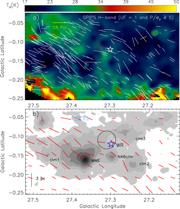
Figure 11. (a) Herschel temperature map is overlaid with the GPIPS H-band polarization vectors (in white) of 249 stars with UF = 1 and P/σp ≥ 5. The H-band polarization vectors of CRS7, CRS10, and the W–R stars are shown in red. The background map is similar to the one shown in Figure 7(a). (b) The integrated 13CO emission map is overplotted with the mean polarization vectors. The background map is similar to the one shown in Figure 3. The mean polarization data are computed by dividing the polarization spatial region into 13 × 7 equal parts, and a mean polarization value of the H-band sources is obtained within each specific part. The marked symbols and labels are similar to those shown in Figure 3. In both panels, the degree of polarization is inferred from the length of each vector. The orientations of the vectors show the galactic position angles of polarization in both panels. In both panels, the "star" symbol indicates the location of the W–R star. A reference vector of 5% is drawn in both panels.
Download figure:
Standard image High-resolution imageThe mean distribution of the H-band vectors appears uniform, however, we notice a little change in the mean polarization pattern between the MME condensation and the W–R star.
The histograms of the degree of polarization and the polarization galactic position angles of the 249 stars are displayed in Figures 12(a) and (b), respectively. The degree of polarization value for the majority of the population is found to be ∼3%. Additionally, we infer an ordered plane-of-the-sky component of the magnetic field with a peak galactic position angle of ∼55°. In Figure 12(c), the GPS NIR color–color diagram of sources confirms that the majority of stars are located behind the N46 molecular cloud. In the NIR color–color diagram, the reddened background stars and/or embedded stars can be identified with (J−H) ≥ 1.0; however the foreground sources can be traced with (J−H) < 1.0.
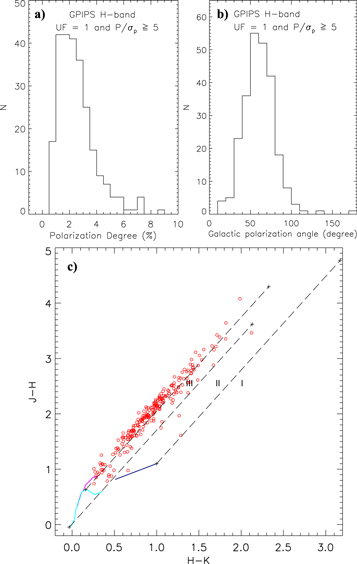
Figure 12. (a) Histogram of the GPIPS H-band polarization degree. (b) The distribution of galactic position angles of the polarization vectors. These plots are shown for stars with UF = 1 and P/σp ≥ 5 (also see Figure 11). (c) NIR color–color diagram (H−K vs. J−H) of the selected GPIPS sources with UF = 1 and P/σp ≥ 5. The solid curves highlight the unreddened locus of main-sequence stars (cyan) and giants (magenta; from Bessell & Brett 1988). The three parallel long-dashed lines show the reddening vectors (with AK = 3 mag) of giants, main-sequence stars, and Classical T Tauri (CTTS) stars. The extinction vectors are extracted from Cohen et al. (1981) extinction laws (AJ/AK = 2.94 and AH/AK = 1.72 for California Institute of Technology (CIT) system). Three different subregions (namely, "I," "II," and "III") are marked in the diagram. The YSOs can be traced in "I" and "II" subregions. CTTS locus (in CIT system; Meyer et al. 1997) is shown as a solid line in navy. The loci of unreddened dwarf (Bessell & Brett (BB) system), giant (BB-system), and colors are transfered into CIT system using transformation relations given in Carpenter (2001). The plot shows that the majority of stars appears behind the N46 molecular cloud (see the text for details).
Download figure:
Standard image High-resolution image4. DISCUSSION
4.1. The Energetics of the WN7 W–R Star
The presence of extended nebulous features around the O and/or W–R stars is often explained by the interaction between the massive stars and their surroundings (Lamers & Cassinelli 1999; Deharveng et al. 2010; Dewangan et al. 2015a, 2015b). Many similar studies, in particular those surrounding W–R stars, have been carried out in recent years (e.g., WR 130, Cichowolski et al. 2015; WR153ab/HD 211853, Vasquez et al. 2010; Liu et al. 2012; WR 23, Cappa et al. 2005; and WR 55, Cappa et al. 2009). The knowledge of various pressure components (pressure of an H ii region (PH ii), radiation pressure (Prad), and stellar wind ram pressure (Pwind)) driven by a massive star can be useful to infer the prominent physical feedback process. A total pressure driven by a massive star on its surroundings can be written as the sum of these three pressure components, i.e., Ptotal =  + Prad + Pwind. In recent years, it is often found that the 8 μm emission surrounds the warm dust emission as well as the ionized emission (e.g., Deharveng et al. 2010; Paladini et al. 2012). In some such sites, it has been reported that the photoionized gas associated with H ii regions appears as the major contributor for the feedback process (Dewangan et al. 2015a, 2015b). However, in the case of bubble N46, the lack of extended ionized emission inside the bubble strongly indicates that the bubble is unlikely to have originated by the expanding H ii region. The spectroscopically characterized source WN7 W–R star appears to be located inside the bubble N46. Here, we estimate only two pressure components Pwind (=
 ) and Prad (=
 ), where
  is the mass-loss rate, Vw is the wind velocity, Lbol is the bolometric luminosity, and Ds is the distance from the location of the W–R star where the pressure components are computed. Adopting the typical values of
  (≈5.0 × 10⁻⁵ M⊙ yr−1) and Lbol (∼106 L⊙) for the WN7 W–R star given in Lamers & Cassinelli (1999) and Prinja et al. (1990), along with Vw (=1600 km s−1) estimated using our observed spectra (see Section 3.1), we obtain the values of Pwind ≈ 1.1 × 10⁻⁹ dynes cm−2 and Prad ≈ 2.88 × 10⁻¹⁰ dynes cm−2 at a distance of 1.93 pc (i.e., an average radius of the bubble). We find Pwind > Prad. Additionally, Pwind is much higher than the pressure associated with a typical cool molecular cloud (PMC ∼10−11–10−12 dynes cm−2 for a temperature ∼20 K and the particle density ∼103–104 cm−3; see Table 7.3 of Dyson & Williams 1980, p. 204). These calculations indicate that the bubble appears to be produced by the stellar wind of the WN7 W–R star. Hence, the bubble N46 can be considered as an example of a stellar wind bubble or a wind-driven bubble (e.g., Castor et al. 1975). From the position–velocity analysis of molecular gas, we infer the presence of an expanding shell with an expansion velocity, Vexp = 3 km s−1.
We estimate the expected mechanical luminosity of the stellar wind (Lw = 
 erg s−1) for the WN7 W–R star using the values of
  and Vw as mentioned above. We obtain Lw ≈ 4 × 1037 erg s−1 for the WN7 W–R star. Using the value of Lw, we infer that the W–R star has injected a large amount of mechanical energy (Ew ≈ 1.3 × 1051 erg) in 1 Myr. During the entire life of a typical WN7 star (4 Myr; see Figure 13.3 given in Lamers & Cassinelli 1999), the star can dump Ew ≈ 5 × 1051 erg in its vicinity. In the environment surrounding WR153ab, Vasquez et al. (2010) also found that the mechanical energy released by the W–R star greatly influenced its vicinity, shaping the ring-like structure of the molecular distribution.
The starlight H-band polarization data allow us to examine the large-scale magnetic field structure projected in sky plane. The magnetic field lines are almost uniformly distributed within the N46 molecular cloud. However, we notice a variation in the distribution of the mean polarization position angles between the MME condensation and the W–R star. We have also found that Pwind is the dominated term compared to Prad. It is known that the aligned dust can be used as a tracer for magnetic fields. In the case of wind bubbles, it is often found that only some amount of the injected mechanical energy will be transferred into kinetic energy of the expanding gas (Weaver et al. 1977; Arthur 2007). Hence, the remaining energy propagates in the surrounding interstellar medium. Considering this fact, the impact of the stellar wind of the W–R star seems to be responsible for the noticeable change in the polarization angles. Note that in this work we are unable to trace the small-scale magnetic field structure toward the dense regions.
4.2. SF Process
In the N46 molecular cloud, SF activities are traced by the presence of compact H ii regions, clusters of YSOs, 6.7 GHz MME, and molecular outflow. In our clustering analysis, we found that the clusters of YSOs are spatially seen toward the molecular condensations, which are associated with a range of temperature and density of about 18–24 K and (0.6–9.2) × 1022 cm−2 (AV ∼ 7–98 mag). Some YSOs are also seen on the edges of the bubble without any clustering. Several compact radio peaks are identified on the edges of the bubble and are consistent with radio spectral types B0V–B0.5V. Infrared images revealed the individual IRcs of three CRSs that have masses (13–20 M⊙) and ages (1–2 Myr). It is evident that SF continues into the N46 molecular cloud. Interestingly, our observational investigation suggests that the early phase of MSF (<0.1 Myr) is occurring in the MME condensation, as traced by the presence of the 6.7 GHz MME. This condensation is the most massive clump and is associated with significant clustering of YSOs and at least one molecular outflow. An embedded IRc of the 6.7 GHz MME is identified and is located within the YSOs cluster. Due to coarse beam size, the GRS 13CO data are limited and cannot allow us to study the gas kinematics within MME condensation. Hence, high-resolution molecular line observations will be helpful to further explore the MME. We also identify an embedded young massive protostar (Mass ∼9 M⊙, AV ∼ 54 mag, and age ∼0.7 Myr) associated with the N46clm clump, which is located near the edge of the bubble. The average ages of Class I and Class II YSOs are generally reported to be ∼0.44 Myr and ∼1–3 Myr (Evans et al. 2009), respectively. In the N46 molecular cloud, we find the presence of an evolved and powerful WN7 W–R star (with typical age ∼4 Myr). It appears that the strong stellar wind from the W–R star has affected its local vicinity, which has been inferred from the presence of a wind-driven bubble/shell. It has been suggested that the stellar winds from O and B stars can induce the formation of massive stars in molecular clouds (Lucy & Solomon 1967, 1970; Morton 1967). We notice the existence of an apparent age gradient between the W–R star and young sources (i.e., YSOs, IRcs of CRSs, and 6.7 GHz MME). Hence, it is most likely that the stellar wind from the WN7 W–R star plays a significant role in the propagation of SF in the N46 molecular cloud. Previously, several authors also presented results in favor of SF induced by the strong wind of the WR stars (e.g., WR 130, Cichowolski et al. 2015; WR153ab/HD 211853, Vasquez et al. 2010; Liu et al. 2012; WR 23, Cappa et al. 2005; and WR 55, Cappa et al. 2009).
To assess the possibility of triggered SF, we computed Pwind values at different distances with respect to the W–R star. The W–R star is situated at a projected linear separation of ∼3.4, ∼4.4, ∼6.5, ∼6.7, and ∼14.1 pc from the N46clm, clm3, clm2, MME, and clm1 molecular condensations. In previous section, we estimated Pwind near the edge, which is equal to be ∼1.1 × 10⁻⁹ dynes cm−2 at Ds = 1.93 pc and is much higher than PMC. We also estimate Pwind ∼0.94 × 10⁻¹⁰ and ∼2.1 × 10⁻¹¹ dynes cm−2 at Ds = 6.7 and 14.1 pc, respectively. The clm1 condensation is located farthest from the W–R star, indicating the impact of wind may not be very strong. Considering the tremendous energy output of the W–R star, the SF activity could be triggered on the edges of the bubble. Furthermore, SF in the N46clm, clm2, clm3, and MME condensations might also be influenced by the feedback of the WN7 W–R star. However, the triggered SF in the clm1 condensation seems unlikely.
5. SUMMARY AND CONCLUSIONS
In this work, we have carried out a multi-wavelength analysis of an MIR bubble N46, which hosts a WN7 W–R star, using new observations along with publicly available archival data sets. The main purpose of this work is to study the SF process in extreme environments (e.g., regions around OB stars and H ii regions). The important outcomes of this multi-wavelength analysis are given below.
- 1.Based on the FWHM of the He ii 2.1885 μm line (i.e., about 110 Å), W–R 1503-160L is classified as a weak-lined WN7 star. Considering the weak-lined WN7 star and its 2MASS photometry, we estimate its distance to be 5.2 ± 0.7 kpc, which is in good agreement with the kinematic distance of the bubble N46 (i.e., 4.8 ± 1.4 kpc). This result indicates that the bubble N46 hosts the W–R 1503-160L star.
- 2.The molecular cloud associated with the bubble N46 (i.e N46 molecular cloud) is well traced in a velocity range of 87–100 km s−1. In the integrated 13CO map, five molecular condensations (clm1, clm2, clm3, N46clm, and MME) are identified within the N46 molecular cloud.
- 3.These molecular condensations are also traced in the Herschel maps with a range of temperature and density of about 18–24 K and (0.6–9.2) × 1022 cm−2 (AV ∼ 7–98 mag), respectively. The masses of the prominent clumps MME, N46clm, clm1, and clm2 are estimated to be ∼7273, ∼954, ∼412, and ∼741 M⊙, respectively.
- 4.The distribution of ionized emission observed in the MAGPIS 20 cm continuum map is mostly seen toward the edges of the bubble. Ten CRSs are identified and each of them is associated with a radio spectral type B0V/B0.5V. Visual inspection of NIR and GLIMPSE images reveals the individual IRcs of three CRSs that have masses 13–20 M⊙ and ages 1–2 Myr.
- 5.The analysis of UKIDSS-NIR, Spitzer-IRAC, and MIPSGAL photometry reveals a total of 370 YSOs. The surface density contours of YSOs are spatially seen toward all the molecular condensations, revealing ongoing SF within the N46 molecular cloud. YSOs are also identified on the edges of the bubble without any clustering.
- 6.The analysis of the gas kinematics of 13CO indicates the signature of an expanding shell with a velocity of 3 km s−1.
- 7.The MME condensation is identified as the most massive and dense clump in the N46 molecular cloud. The MME clump shows intense SF activity and also contains a 6.7 GHz MME with radio continuum detection. An embedded IRc of the 6.7 GHz MME is identified. The MME condensation contains at least one molecular outflow.
- 8.The N46clm condensation harbors an embedded protostar that has physical parameters: mass: 9 ± 3 extinction: 54 ± 19 mag; and age: 0.67 Myr.
- 9.The pressure calculations (Prad and Pwind) indicate that the stellar wind associated with the WN7 W–R star (with a mechanical luminosity of ∼4 × 1037 erg s−1) can be considered as the major contributor for the feedback mechanism.
- 10.A deviation of the H-band starlight mean polarization angles around the bubble also traces the feedback process. The strong stellar wind from the WN7 W–R star (with typical age ∼4 Myr) has influenced its local vicinity. The W–R star is located at a projected linear separation of ∼3.4, ∼4.4, ∼6.5, ∼6.7, and ∼14.1 pc from the N46clm, clm3, clm2, MME, and clm1 molecular condensations.
- 11.Our analysis has revealed that SF continues into the N46 molecular cloud. The cloud also harbors massive young stars. In the N46 cloud, there exists an apparent age gradient between the W–R star and young sources (YSOs, IRcs of CRSs, and 6.7 GHz MME).

Taking into account all the observational results obtained with our multi-wavelength analysis, we conclude that there is a possibility of triggered SF toward the edges of the bubble. Furthermore, the SF activities in the N46clm, clm2, clm3, and MME condensations appear to be influenced by the energetics of the WN7 W–R star.
We thank the anonymous reviewer for a critical reading of the manuscript and several useful comments and suggestions, which greatly improved the scientific content of the paper. The research work at the Physical Research Laboratory is funded by the Department of Space, Government of India. This work is based on data obtained as part of the UKIRT Infrared Deep Sky Survey. This publication made use of data products from the Two Micron All Sky Survey (a joint project of the University of Massachusetts and the Infrared Processing and Analysis Center/California Institute of Technology, funded by NASA and NSF), archival data obtained with the Spitzer Space Telescope (operated by the Jet Propulsion Laboratory, California Institute of Technology under a contract with NASA). This publication makes use of molecular line data from the Boston University-FCRAO Galactic Ring Survey (GRS). The GRS is a joint project of Boston University and Five College Radio Astronomy Observatory, funded by the National Science Foundation (NSF) under grants AST-9800334, AST-0098562, and AST-0100793. This publication makes use of the Galactic Plane Infrared Polarization Survey (GPIPS). The GPIPS was conducted using the Mimir instrument, jointly developed at Boston University and Lowell Observatory and supported by NASA, NSF, and the W.M. Keck Foundation. A.L. acknowledges the CONACYT (México) grant CB-2012-01-1828-41. I.Z. is supported by the Russian Foundation for Basic Research (RFBR).