


Abstract
We present 2D hydrodynamics simulations of near-Chandrasekhar-mass white dwarf (WD) models for Type Ia supernovae (SNe Ia) using the turbulent deflagration model with a deflagration-to-detonation transition (DDT). We perform a parameter survey for 41 models to study the effects of the initial central density (i.e., WD mass), metallicity, flame shape, DDT criteria, and turbulent flame formula for a much wider parameter space than in earlier studies. The final isotopic abundances of 11C to 91Tc in these simulations are obtained by post-process nucleosynthesis calculations. The survey includes SN Ia models with the central density from 5 × 10⁸ g cm−3 to 5 × 10⁹ g cm−3 (WD masses of 1.30–1.38 M⊙), metallicity from 0 to 5 Z⊙, C/O mass ratio from 0.3 to 1.0, and ignition kernels, including centered and off-centered ones. We present the yield tables of stable isotopes from 12Cl to 70Zn, as well as the major radioactive isotopes for 33 models. Observational abundances of 55Mn, 56Fe, 57Fe, and 58Ni obtained from the solar-composition, well-observed SN Ia and SN Ia remnants are used to constrain the explosion models and the SN progenitor. The connection between the pure turbulent deflagration model and the subluminous SNe Iax is discussed. We find that dependencies of the nucleosynthesis yields on the metallicity and the central density (WD mass) are large. To fit these observational abundances, and also for the application of galactic chemical evolution modeling, these dependencies on the metallicity and WD mass should be taken into account.
Export citation and abstract BibTeX RIS
1. Introduction
Type Ia supernovae (SNe Ia) have been shown to be the major source of many iron-peak elements in the galaxies (e.g., Nomoto et al. 1984, 1994; Arnett 1996; Matteucci 2001, 2012; Nomoto & Leung 2017, 2018). To understand how SNe Ia contribute to the metal enrichment process in the galaxies, and to explain the growing diversities of the observational results, simulations of SN Ia models with much wider parameter ranges need to be done.
SNe Ia have been well modeled by the thermonuclear explosions of carbon–oxygen white dwarfs (WDs; e.g., Hillebrandt & Niemeyer 2000). Both the Chandrasekhar-mass WD model and sub-Chandrasekhar-mass WD model can be consistent with the similarity of SN Ia light curves (e.g., Branch & Wheeler 2017). The empirical similarity later leads to the discovery of accelerating cosmological expansion and the existence of dark energy (Riess et al. 1998; Perlmutter et al. 1999).
However, recent observations have suggested that there exists a wide diversity in SNe Ia (see, e.g., a review by Taubenberger 2017). In addition to previously known variations ranging from luminous SNe Ia (super-Chandrasekhar and SN 1991T-like) to SN 1991bg-like faint SNe Ia, a new subclass of SN 2002cx-like, or SNe Iax (see, e.g., a recent review by Jha 2017) and SN 2002es-like SNe (e.g., Taubenberger 2017), has been reported. Such brightness variations imply a large variation of the 56Ni mass (∼0.1–1.4 M⊙) produced in the explosions.
Studies of nucleosynthesis of 1D models have shown some important dependencies on the model parameters. For example, Fe-peak elements synthesized in the Chandrasekhar-mass model W7 (Nomoto et al. 1984) are shown to be consistent with the solar abundances, except for a significant overproduction of 58Ni,where the rate of electron capture is important (e.g., Thielemann et al. 1986; Iwamoto et al. 1999; Mori et al. 2016). The solar abundance pattern of Fe-peak elements can also be reproduced by the sub-Chandrasekhar models with solar metallicity (e.g., Shigeyama et al. 1992; Nomoto et al. 1994), although the Ni/Fe ratio (which depends on metallicity) tends to be under solar because of the low central density of exploding WDs. As shown in [Ni/Fe] mentioned above, the central density of the WD is an important parameter because of the level of electron capture. If the central density is high enough, synthesis of certain neutron-rich isotopes, such as 48Ca, 50Ti, and 54Cr, can be significant (Woosley 1997).
Another interesting example is [Mn/Fe], which increases with increasing [Fe/H] in the Galactic halo (e.g., Hinkel et al. 2014; Mishenina et al. 2015). [Mn/Fe] in metal-poor stars in dwarf spheroidal galaxies (e.g., Larsen et al. 2014; Sbordone et al. 2015) provides further information on metallicity dependence. In order to calculate the chemical evolution of dwarf spheroidal galaxies, metallicity-dependent SN Ia yields are necessary (e.g., Kobayashi et al. 2015).
Recent observations of SN Ia remnants in the nebular phase have provided important insights into the models of SNe Ia. They include Tycho (Yamaguchi et al. 2015), Kepler (Park et al. 2013), and 3C 397 (Yamaguchi et al. 2015). The relative X-ray flux of iron-peak elements can give promising constraints on the explosion conditions. For example, these three remnants have been suggested to have progenitors with supersolar metallicity (Yamaguchi et al. 2015).
These would suggest the importance of obtaining the SN Ia yields for a wide range of environmental conditions, such as metallicity and the mass (and thus the central density) of the WDs.
Such a study will be important for the future use of galactic chemical evolution for an accurate modeling of isotopes as a function of metallicity. Nucleosynthesis of multidimensional hydrodynamics simulations was made in Travaglio et al. (2004) with the use of a tracer particle scheme (Seitenzahl et al. 2010). The effects of the initial flame structure on the chemical yield were studied in Maeda et al. (2010), Fink et al. (2014), and Seitenzahl et al. (2013) for different explosion models.
A few more recent works have studied these objects. Shen et al. (2018) revisited the sub-Chandrasekhar SN Ia models and showed that the sub-Chandrasekhar SNe Ia can be connected to the remnant 3C 397 when an appropriate amount of reverse shock-heating is considered. Similar explorations were done in Dave et al. (2017), where some representative models of pure turbulent deflagration, deflagration-to-detonation transition (DDT), and gravitationally confined detonation are explored. It is shown that for a subset of central densities, C/O ratio and high offset in the initial flame allow models to produce supersolar [Mn/Fe] to match the observed data. See, e.g., Nomoto & Leung (2017) for a general review of the nucleosynthesis pattern and its connection to the explosion mechanism.
Such results indicate that properties of these SNe Ia might have important metallicity effects. Nucleosynthesis in SNe Ia has been studied extensively, but still only a small parameter space has been explored.
In view of this background, we make a systematic modeling of SNe Ia for various explosion configurations and settings to see how the model parameters of SNe Ia affect the WD explosions and their chemical yields for Chandrasekhar-mass WDs for a much wider range of parameters (i.e., WD masses [central densities], metallicity, flame structure). In a forthcoming paper, we will present our sub-Chandrasekhar-mass models. The chemical yields of SNe Ia, which depend on the model parameters and environmental conditions, can be constrained by the observed abundance patterns of Fe-peak elements in various stars and systems.
We use our own 2D hydrodynamics code (see Appendix A), because our 2D hydro code is more suitable to calculate many models for a wide range of parameters than the 3D hydro code. The typical running time for one 2D model is approximately days on a single machine, while it takes weeks to months for a cluster to calculate the explosion phase of a model in 3D. Certainly, the 2D simulations have some qualitative differences from the 3D simulations in two ways. First, the flame in 2D models tends to propagate faster than in 3D models because of the larger surface area for the same 2D projection. Second, the imposed symmetry may enhance the growth of hydrodynamical instabilities owing to the imposed reflective boundaries, which stimulate the growth of boundary flows.
In Section 3 we construct the benchmark to be a typical SN Ia model. In Section 4, we present the nucleosynthesis yields of our models and show how large the effects of each model parameter are. We then discuss how our results can be applied to observational data to constrain the model parameter. In Section 5 we compare our results with earlier calculations. In Appendix A, we summarize the numerical code, which is specifically developed for modeling SNe Ia (Leung et al. 2015b). We describe the updates and changes in the hydrodynamics and nucleosynthesis. Finally, in order to apply for the chemical evolution modeling and comparison with observational data, we present tables of the nucleosynthesis yields of our 24 models.
2. Initial Models and Methods
2.1. Initial Models
We construct the initial C + O WD models at the central carbon ignition with the masses from M = 1.30 to 1.39 M⊙ (and thus the central densities from 5 × 10⁸ g cm−3 to 5 × 10⁹ g cm−3) for various metallicities and the carbon fraction (see Section 4 for details). The internal temperature is assumed to be 1 × 10⁸ K.
To carry out the 2D simulations, we set the model parameters as follows. For each CO WD, we choose a given central density ρc, metallicity Z, and CO mass ratio C/O with an isothermal profile. Then we follow the hydrodynamics simulation without further alternation. In the initial model, we solve the hydrostatic equilibrium of the WD assuming a constant composition and a constant C/O. To model metallicity in the simplified network, we treat 22Ne as the proxy of metallicity.
The above initial model for the simulation of the explosion is a simplified approximation of the realistic evolutionary model of an accreting WD from its formation through the initiation of a deflagration. To clarify the simplification of our initial model, let us compare with the evolutionary models calculated by Nomoto et al. (1976, 1984).
In Nomoto et al. (1976, 1984), the initial mass of a C + O WD is 1.0 M⊙, with uniform mass fractions of C, O, and 22Ne as X(C) = 0.475, X(O) = 0.50, and X(22Ne) = 0.025. Here 22Ne is converted from the initial CNO elements during H and He burning so that X(22Ne) is treated as the proxy of initial metallicity. In the present initial models, we also adopt a uniform abundance distribution with X(O) = 0.50 and X(C) = 0.50–X(22Ne), where different X(22Ne) is the proxy of different metallicity. X(22Ne) = 0.025 is regarded as the solar metallicity, although the latest solar abundances correspond to X(22Ne) = 0.0134 (Asplund et al. 2009).
In Nomoto et al. (1976, 1984), the WD is cooled down to the central temperature of Tc = 108 and 107 K for the two cases, respectively, with almost isothermal distribution. Afterward, mass accretion onto the WD starts with different accretion rates, which give the rate of compressional heating of the WD interior.
In the SD scenario, the WD mass (and thus the central density) increases by mass accretion from the companion star (e.g., Nomoto et al. 1994). The internal temperature depends on the competition between the compressional heating and radiative cooling (e.g., Nomoto 1982a, 1982b). For a higher accretion rate, the central temperature increases faster and carbon is ignited at the center at a lower central density (and thus a smaller WD mass).
For heating, heat inflow from the H/He shell burning is also important (Nomoto et al. 1984). Since the timescale of heat conduction in the WD interior is shorter than the accretion timescale, the WD interior is close to isothermal with a temperature of ∼108 K (Nomoto et al. 1984).
In this way, the adopted WD masses at the carbon ignition correspond to different mass accretion rates from the companion stars (Nomoto et al. 1984) and/or the delay time in uniformly rotating WDs (Benvenuto et al. 2013).
We should note that the highest accretion rate for the central carbon ignition is limited to ∼7 × 10⁻⁷ M⊙ yr−1 by the rate of steady hydrogen burning above which a strong WD wind blows (Nomoto et al. 2007; Kato et al. 2014), or to ∼3 × 10⁻⁶ M⊙ yr−1 by the off-center carbon ignition for the accretion of He from an He star companion (Nomoto & Iben 1985). For these limitations, the lowest WD mass at the carbon ignition is ∼1.35 M⊙ (Nomoto et al. 1984).
After C ignition in the center due to strong screening effects, a simmering phase starts with a developing convective core, which was calculated using the time-dependent mixing length theory (Unno 1967; Nomoto et al. 1976, 1984; for recent works on simmering phase, see, e.g., Piro & Chang 2008; Jackson et al. 2010; Krueger et al. 2012; Ohlmann et al. 2014; Martinez-Rodringuez et al. 2016). In these calculations, so-called convective Urca processes were not included. The extent of the convective core might be limited by convective Urca processes, although it is quite uncertain (e.g., Arnett 1996; Lesaffre et al. 2006), In view of the large uncertainty of convective Urca processes, the exact distributions of the temperature and abundances in the WD should be regarded as highly uncertain, and further study of the simmering phase is necessary (see, e.g., Piro & Chang 2008, for an analytic analysis). We study the effects of the initial C/O ratio as the origin of model diversity.
Near the end of the simmering phase in the models by Arnett (1969) and Nomoto et al. (1976, 1984), it was found that a superadiabatic temperature gradient appears at the central temperature of Tc > 8 × 10⁸ K and increases sharply. The timescale of the temperature rise becomes shorter than the dynamical timescale around Tc > 3 × 10⁹ K. At Tc > 5 × 10⁹ K, nuclear reactions become rapid enough to realize nuclear statistical equilibrium (NSE), and Tc ∼ 1010 K is reached. The steep temperature jump, i.e., a deflagration front, is formed. Such an evolution through NSE takes place in a timescale shorter than the convective energy transport timescale, and the convective core size and the abundances in the bulk of the convective core are frozen, i.e., nuclear burning products in the center are not well mixed with the outer layers.
In the deflagrated region, NSE is realized so that the details of the abundance change during rapid nuclear reaction are not important. A decrease in Ye due to electron capture during the simmering phase is also negligibly small compared with electron capture after NSE is realized. Thus, the neglect of the convective region and the composition change during the simmering phase do not much affect the current results.
We also note that, owing to the degenerate electron gas, the mass and radius are less sensitive to the choice of temperature profile. We observe that the masses, radii, and density profiles are still comparable to those presented in the literature (see, e.g., Krueger et al. 2010, for the WD model obtained from the stellar evolutionary model).
In the present study, we extend the WD mass down to the range of 1.30–1.35 M⊙. Such low WD masses may be called sub-Chandrasekhar masses. The central carbon ignition in such a sub-Chandrasekhar-mass WD would be possible by shock compression of the central region due to the surface He detonation (e.g., Arnett 1996). The important difference from those "double-detonation" models is that, because of the relatively large WD mass and thus the high central density, the central carbon ignition does not necessarily produce strong shock waves to induce the detonation, but rather develops a carbon deflagration due to the large electron-degeneracy pressure compared with the thermal pressure released by nuclear burning (Nomoto et al. 1976). Whether the surface He detonation induces the carbon deflagration or direct detonation will be studied in forthcoming papers.
2.2. Input Physics
Here we briefly describe the new input physics used in the code. For the basic data structure of the code and the code test, we refer the readers to Leung et al. (2015b). We also refer the readers to Appendix A for the numerical implementation of the SN Ia physics in our code. Here we only list the parts relevant to SNe Ia. We use the most recent rates we have for describing the microphysics, including the Helmholtz equation of state (Timmes 1999), nuclear reaction rates (Rauscher & Thielemann 2009), the strong screening factor (Kitamura 2000), and electron capture rates (Langanke & Martinez-Pinedo 2001).
2.3. Methods
In the present study, we assume that the central carbon flash develops into the deflagration as follows. The exact pattern of the initial flame is not well constrained. To trigger the deflagration phase, therefore, we impose a flame by hand in the star. The zone is assumed to be incinerated into NSE. We choose two different morphologies. First, it is a centered flame with some sinusoidal perturbations. This is similar to the c3 flame as used in Reinecke et al. (1999a), which mimics that the flame grows at center and then is perturbed by Rayleigh–Taylor instabilities. Second, it is an off-center "bubble" (in 2D the bubble corresponds to a ring in 3D), similar to b1 in Reinecke et al. (1999a). This pattern mimics the evolution that the convection in the star is rapid enough to bring the hot parcel from the center before it runs away.1
To determine the DDT, we compare the eddy turnover scale with the flame width, i.e., the Karlovitz number, Ka, which is defined as (Niemeyer et al. 1995)

Here lflame and lturb are the representative length scale of the deflagration wave and the turbulent eddy motion (see Appendix A for details). At the end of each time step we scan across the flame surface to see whether the Karlovitz number, Ka, satisfies the DDT condition, for which we pick Ka = 1 to be the required DDT condition. Once this condition is satisfied, we put in the initial C detonation in the form of a 2D bubble (a ring) at that point and allow that detonation to freely evolve. Extra detonation bubbles are added as long as the flame surface is not yet swept by the detonation wave. We follow the evolution until the whole star expands sufficiently that it becomes sparse and cold and all electron capture and major nuclear reactions have stopped.
We emphasize that there still exists theoretical uncertainties in the DDT model, especially related to the robustness of trigger detonation in an unconfined media (see Appendix E for a comparison of how this certainty affects the nucleosynthesis).
3. Benchmark Model of Typical SNe Ia
In doing the comparison, we first describe the parameters for the benchmark model, its hydrodynamic behavior, and nucleosynthesis. The benchmark model is assumed to represent a statistical average of the SNe Ia that we observed, i.e., with solar metallicity, ∼0.6 M⊙ of 56Ni, and composition compatible with the solar abundance. This allows us to calibrate the validity of our models. For example, models that produce incompatible chemical abundances are regarded as less frequent events in nature, thus casting constraints on the parameter space correspondingly.
In Table 1 we tabulate the basic stellar parameters we found in producing the benchmark model. In Figure 1 we plot the temperature in color and the deflagration and detonation wave fronts at the moment of the first DDT and at 0.1 s after the first DDT. At the moment of DDT (top panel), the flame has developed from its initial size of ∼100 km to a size of ∼2000 km. We also mark the first four detonation spots by crosses in both figures, where the transition density is ∼2 × 10⁷ g cm−3. It can be seen that the initial DDT occurs on the "fingers" near the axis. We remind the reader that DDT can occur on the flame surface when the criteria are satisfied, and that the flame surface is not yet swept by the detonation wave. The whole deflagration ash is still hot at a temperature of ∼(5–6) × 109 K. A thin ring of radius ∼ 3500 km can be seen owing to the excitation of the initial flame that is artificially triggered. The sudden pulse creates a weak heating to that part up to 2 × 10⁹ K. At 0.1 s after DDT (bottom panel), the flame continued to grow to a size of ∼2500 km owing to thermal expansion. The deflagration ash has drastically cooled down to a temperature of ∼(4–5) × 109 K. The detonation wave has quickly covered the deflagration front. Due to a lower density, the detonation ash is in general cooler, about 3 × 10⁹ K. An exception appears when the detonation wave collides with the symmetry boundary or another detonation wave. In these cases, the shock compression can easily increase temperature above 5 × 10⁹ K.

Figure 1. Top panel: temperature color plot together with the deflagration when the first detonation is triggered. The solid line contour stands for the deflagration front, and the crosses stand for the first four positions whose DDT criteria are satisfied. Bottom panel: similar to the top panel, but at 0.1 s after the first DDT is triggered. The solid (dashed) line stands for the deflagration (detonation) front. The crosses are the same as above. We remind the reader that in the simulations the detonation is triggered only along the deflagration front. In this figure the crosses lie inside the deflagration because of fluid advection.
Download figure:
Standard image High-resolution imageTable 1. Model Setup for the Benchmark Model
| Model | ρc(NM) | Metallicity | Flame Shape | Ka | M | R | Ye(min) | Enuc | Etot | tDDT | MNi | MMn |
|---|---|---|---|---|---|---|---|---|---|---|---|---|
| 300-1-c3-1 | 3 | 1 | c3 | 1 | 1.38 | 1900 | 0.462 | 17.7 | 12.7 | 0.78 | 0.63 | 9.55 × 10⁻³ |
Note. Central densities of NM ρc(NM) are in units of 109 g cm−3. Metallicity is in units of solar metallicity. The total mass M and the final nickel-56 mass MNi are in units of solar mass. Ka is the critical Karlovitz number above which C detonation is assumed to occur in our simulations. See also Appendix A for further details of the DDT criteria. R is the initial stellar radius in kilometers. Enuc and Etot are the energy released by nuclear reactions and the final total energy, respectively, both in units of 1050 erg. Ye(min) is the minimum value of the electron fraction within the simulation box at the end of the simulation. tDDT is the first detonation transition time in units of seconds. MNi and MMn are the masses of 56Ni of MMn at the end of simulations, after all short-lived radioactive isotopes have decayed.
Download table as: ASCIITypeset image
In Figure 2 we plot the nuclear energy generation rate and its components as a function of time for the benchmark model. We show separately the nuclear energy generation rate by deflagration and by detonation. In Figure 3 we plot the total energy and its components as a function of time. For a more detailed discussion about the hydrodynamics evolution of the benchmark model, we refer the readers to Appendix B.

Figure 2. Total energy generation rate and its components as a function of time for the benchmark model. The solid line corresponds to the total energy generation rate; the dotted, dashed, and dot-dashed lines correspond to the luminosity by carbon deflagration, carbon detonation, and NQSE+NSE burning, respectively.
Download figure:
Standard image High-resolution image
Figure 3. Total energy and its components as a function of time for the benchmark model. The solid line corresponds to the total energy; the dotted, dashed, and dot-dashed lines correspond to the total kinetic, internal, and absolute value of gravitational potential energy, respectively.
Download figure:
Standard image High-resolution image3.1. Pure Turbulent Deflagration Phase
We show in Figure 1 the temperature color plot and the deflagration wave fronts. At early phase, the matter density is sufficiently high that most matter is incinerated into NSE (including endothermic photodisintegration of 56Ni into 4He). In the first 0.8 s, deflagration takes place, where the energy release is slow. The deflagration wave and its subsequent advanced burning release about 1051 erg s−1.
In the pure turbulent deflagration phase before the DDT, namely, from t = 0 to 1.12 s, deflagration burns about 0.3 M⊙ of matter. As seen in Figure 2, the deflagration releases nuclear energy slowly, on the order of 1050 erg s−1. The nuclear energy production is slow so that the total energy of the WD increases but remains negative.
During the deflagration phase, the star expands considerably. As the flame front reaches the low-density region (∼107 g cm−3) beyond t = 0.8 s, the carbon deflagration releases much less energy than what it originally does at the stellar core. The drop of luminosity near t = 1 s suggests that the matter has expanded and cooled down so that the NSE timescale becomes comparable to or even longer than the hydrodynamics timescale.
3.2. Detonation Phase
When the density at the flame front decreases to ≈2.3 × 10⁷ g cm−3, the transition to the detonation takes place. We plot in Figure 1 the temperature color plot and the detonation wave fronts. The detonation starts from the tip of the finger shape, around r = 2000 km. The detonation wave is almost unperturbed by the fluid motion, so that the flame structure appears to be almost spherical. The temperature profile shows that most matter is no longer in NSE. Due to the uneven surface of the flame at the moment of DDT, there is unburnt material left behind in the high-density region. At the radius defined by the outermost radius reached by the deflagration wave, there always exists fuel inside. This matter is later burnt into NSE by the detonation wave. This provides an additional source of iron-peak elements. Notice that this feature does not exist in 1D models because the spherical model allows all matter to be burnt inside the same outermost radius reached by the flame. Therefore, the detonation can only burn the low-density matter and produce fewer iron-peak elements.2
The detonation wave quickly burns the remaining material, making the total energy positive. Then the WD expands rapidly and increases its kinetic energy. In contrast to the slow deflagration wave, the detonation is a much more efficient source for producing nuclear energy. It burns the 1.0 M⊙ matter within the next 0.2 s. The typical luminosity is of the order of 1052 erg s−1.
3.3. Explosive Nucleosynthesis
The chemical composition of the ejected matter is presented. To obtain the nucleosynthesis yield, we use the tracer particle scheme to keep track of the thermodynamics history. Then, we calculate nucleosynthesis by using a 495-isotope network, which includes isotopes from 1H to 91Tc. Stable neutron-rich isotopes, such as 48Ca, 50Ti, 54Cr, and 60Fe, are included so that the nucleosynthesis with electron capture can be consistently calculated for Ye = 0.45–0.50. Here  , with Zi and Ai being the atomic number and mass number, respectively, of the species i. For convenience in this paper, we use Ye = Zi/Ai for the individual species i as well. For the numerical details, see Appendix A.
In Figure 4 we plot [Xi/56Fe] of stable isotopes, after the decay of short-lived radioactive elements is accounted for. All quantities are given by ![$[{{\rm{X}}}_{i}{/}^{56}\mathrm{Fe}]={\mathrm{log}}_{10}(({X}_{i}/X{(}^{56}\mathrm{Fe}))/({X}_{i}/X{{(}^{56}\mathrm{Fe}))}_{\odot }))$](https://content.cld.iop.org/journals/0004-637X/861/2/143/revision1/apjaac2dfieqn2.gif) . It can be seen that in general a considerable number of elements have [Xi/56Fe] between −0.3 and 0.3 as marked in the figure. This shows that these elements are consistent with the solar abundances. Notice that many elements in the Sun come from both SNe Ia and SNe II. For the case of underproduction, it is possible that such isotopes may come solely from SNe II, such as the α-chain isotopes. However, for the case of overproduction, it will be a strong constraint for that particular SN Ia model. This is because the typical rate of SNe Ia has the same order of magnitude as SNe II. Any severe overproduction of such an isotope, for instance, 10 times above solar abundance, means that such an explosion model is not a typical one, since that isotope cannot be "diluted" by the underproduction (or null production) of the other type of SN. Representative elements include 28Si, 32S, 36Ar, 40Ca, 50 −52Cr, 55Mn, 54–57Fe, and 58–62Ni. However, 50Ti and 66Zn are underproduced. Furthermore, isotopes with an odd-number atomic number, such as P, Cl, and K, are mostly underproduced, with the exception of 51V. This is expected, as the system is initially void of hydrogen for proton capture. In this benchmark model, we observed the production of 56Ni to be 0.67 M⊙, 3.34 × 10⁻² M⊙ neutron-rich species (such as 48–50Ti, 53–54Cr, 57–58Fe, and 61–64Ni), and 0.385 M⊙ intermediate-mass elements (IMEs). For the detailed velocity distribution of the products by pure turbulent deflagration, we refer to Section 4.7 for a more detailed discussion.
. It can be seen that in general a considerable number of elements have [Xi/56Fe] between −0.3 and 0.3 as marked in the figure. This shows that these elements are consistent with the solar abundances. Notice that many elements in the Sun come from both SNe Ia and SNe II. For the case of underproduction, it is possible that such isotopes may come solely from SNe II, such as the α-chain isotopes. However, for the case of overproduction, it will be a strong constraint for that particular SN Ia model. This is because the typical rate of SNe Ia has the same order of magnitude as SNe II. Any severe overproduction of such an isotope, for instance, 10 times above solar abundance, means that such an explosion model is not a typical one, since that isotope cannot be "diluted" by the underproduction (or null production) of the other type of SN. Representative elements include 28Si, 32S, 36Ar, 40Ca, 50 −52Cr, 55Mn, 54–57Fe, and 58–62Ni. However, 50Ti and 66Zn are underproduced. Furthermore, isotopes with an odd-number atomic number, such as P, Cl, and K, are mostly underproduced, with the exception of 51V. This is expected, as the system is initially void of hydrogen for proton capture. In this benchmark model, we observed the production of 56Ni to be 0.67 M⊙, 3.34 × 10⁻² M⊙ neutron-rich species (such as 48–50Ti, 53–54Cr, 57–58Fe, and 61–64Ni), and 0.385 M⊙ intermediate-mass elements (IMEs). For the detailed velocity distribution of the products by pure turbulent deflagration, we refer to Section 4.7 for a more detailed discussion.

Figure 4.
![$[{{\rm{X}}}_{i}{/}^{56}\mathrm{Fe}]$](https://content.cld.iop.org/journals/0004-637X/861/2/143/revision1/apjaac2dfieqn3.gif) of stable isotopes in the benchmark model after the short-lived radioactive isotopes have decayed. The ratios are scaled with the solar value. The lines at ±0.3 (corresponding to 0.5 or 2.0 times the solar value) are included.
of stable isotopes in the benchmark model after the short-lived radioactive isotopes have decayed. The ratios are scaled with the solar value. The lines at ±0.3 (corresponding to 0.5 or 2.0 times the solar value) are included.
Download figure:
Standard image High-resolution imageIn Figure 5 we plot the velocity distribution of major isotopes for the benchmark model at the end of simulations for the polar slide from 0° to 9° (Slice 1). The chemical composition is again obtained from the post-processing nucleosynthesis. The figure is consistent with the standard framework that the inner part, namely, matter with low velocity, contains mostly 56Ni. 54Fe and 58Ni are located at the innermost part. In matter with v ≈ 7200 km s−1, IMEs such as 28Si and 32S become prominent. This corresponds to the flame entering the low-density region. For v ≈ 6600 km, there is an abrupt jump of 56Ni again, which results from detonation near the flame edge, where part of the matter has a density of ∼108 g cm−3. Close to v ≈ 9000 km s−1, IMEs becomes prominent again. At the outermost part, the density is too low for nuclear reaction beyond carbon burning, even for detonation. A trace of 16O is left behind.

Figure 5. Velocity profiles of major isotopes for the benchmark model for angles from 0° to 9°.
Download figure:
Standard image High-resolution imageIn Figure 6, we make a plot similar to Figure 5, but for the polar slide of 36°–45° (Slice 5). We choose this slide so as to provide a contrast on the time difference between the quenching of deflagration and the arrival of the detonation wave. As shown in Figure 1, detonation starts from the two opposite "fingers" of the far end of the flame, but not the central "finger." This means that, before the detonation wave reaches the central "finger," the matter around has a certain time to expand before being incinerated. Similar to the previous case, isotopes with Ye < 0.50 are mostly found in the core, where v < 3000 km s−1. The velocity space up to v ≈ 6000 km s−1 is filled with 56Ni. The IME gap in this case is larger than that of slice 1, for which almost no 56Ni is detected from v = 5400 to 7200 km s−1. The second peak of 56Ni appears near v = 7800 km s−1. Close to v ≈ 9000 km s−1, the IMEs become prominent. Different from Slice 1, 16O appears in matter with a velocity slightly less than 8000 km s−1 and also beyond for two distinctive reasons. For v < 7800 km s−1, the remaining 16O comes from the tip of deflagration, while for v between 7800 and 9000 km s−1, 16O appears owing to the longer expansion time between the end of deflagration and detonation. The amount of unburnt 16O is comparatively higher than that in Slice 1.

Figure 6. Velocity profiles of major isotopes for the benchmark model for angles from 36° to 45°.
Download figure:
Standard image High-resolution imageWe further classify the chemical yields of the tracer particles by checking whether they reach their runaway by being swept by the deflagration or detonation wave. Notice that it is possible that the tracer particles, first swept by the deflagration wave, are reheated by the shock collision from the detonation wave. In these cases we still regard the chemical yield to be contributed by the deflagration wave. In Figure 7 we plot their corresponding chemical composition ratio to 56Fe scaled with solar abundance, together with the total yield. It can be seen that the deflagration wave, similar to the 1D model, contributes mostly to the formation of iron-peak elements, especially neutron-rich ones. For example, it has a higher ![$[{{\rm{X}}}_{i}{/}^{56}\mathrm{Fe}]$](https://content.cld.iop.org/journals/0004-637X/861/2/143/revision1/apjaac2dfieqn4.gif) fraction for 54Cr, 55Mn, 54Fe, 58Ni, and 59Co. On the other hand, detonation, which swept mostly the low-density region, produces less massive isotopes. IMEs such as 28Si, 32S, 36Ar, and 40Ca are mostly produced in the detonation wave. Some lighter iron-rich elements, such as 46,48,49Ti and 54Cr, are also produced by detonation. As mentioned before, the unburnt field surrounded by the detonation wave is most of the time swept by the detonation wave, which produces the necessary heating for producing iron-peak elements. As a result, one can observe its contribution to iron-peak elements, including 62Ni and 66Zn.
fraction for 54Cr, 55Mn, 54Fe, 58Ni, and 59Co. On the other hand, detonation, which swept mostly the low-density region, produces less massive isotopes. IMEs such as 28Si, 32S, 36Ar, and 40Ca are mostly produced in the detonation wave. Some lighter iron-rich elements, such as 46,48,49Ti and 54Cr, are also produced by detonation. As mentioned before, the unburnt field surrounded by the detonation wave is most of the time swept by the detonation wave, which produces the necessary heating for producing iron-peak elements. As a result, one can observe its contribution to iron-peak elements, including 62Ni and 66Zn.

Figure 7. Relative chemical abundance to 56Fe of the benchmark model after the short-lived radioactive isotopes have decayed for the deflagration and detonation regions in the benchmark model. The ratios are scaled with the solar value.
Download figure:
Standard image High-resolution image4. Parameter Survey
In this section, we study the dependence on model parameters of carbon–oxygen WDs, by comparing the results with the benchmark model. In Table 2, we tabulate all model parameters and their global results from hydrodynamics and nucleosynthesis. We follow the nomenclature in the literature (Reinecke et al. 1999a) that the c3 flame corresponds to the central burning configuration, with a three-finger structure to mimic the initial Rayleigh–Taylor instabilities. b1a (b1b) is the one-ring configuration at 50 (100) km from the center. In Tables 3–5 we list the nucleosynthesis yield of the stable isotopes in the representative models and in Tables 6–8 the nucleosynthesis yield of the radioactive isotope.
Table 2. Model Setup for the Benchmark Model
| Model | ρc(NM) | Metallicity | Flame Shape | X12C | M | R | Ye(min) | Enuc | Etot | tDDT | MNi | Others |
|---|---|---|---|---|---|---|---|---|---|---|---|---|
| 050-0-c3-1 | 0.50 | 0 | c3 | 0.50 | 1.30 | 3060 | 0.488 | 18.5 | 14.6 | 1.34 | 0.97 | ⋯ |
| 050-1-c3-1 | 0.50 | 1 | c3 | 0.49 | 1.30 | 3060 | 0.488 | 18.3 | 14.4 | 1.34 | 0.89 | ⋯ |
| 050-1-c3-1P | 0.50 | 1 | c3 | 0.49 | 1.30 | 3060 | 0.488 | 5.0 | 1.1 | N/A | 0.21 | only def. |
| 050-1-c3-1D | 0.50 | 1 | c3 | 0.49 | 1.30 | 3060 | 0.488 | 19.2 | 15.3 | N/A | 1.14 | only det. |
| 050-3-c3-1 | 0.50 | 3 | c3 | 0.47 | 1.30 | 3060 | 0.488 | 17.6 | 13.7 | 1.35 | 0.74 | ⋯ |
| 050-5-c3-1 | 0.50 | 5 | c3 | 0.45 | 1.30 | 3060 | 0.488 | 17.3 | 13.3 | 1.35 | 0.63 | ⋯ |
| 075-0-c3-1 | 0.75 | 0 | c3 | 0.50 | 1.31 | 2600 | 0.482 | 18.4 | 14.2 | 1.19 | 0.90 | ⋯ |
| 075-1-c3-1 | 0.75 | 1 | c3 | 0.49 | 1.31 | 2600 | 0.482 | 18.1 | 13.9 | 1.19 | 0.81 | ⋯ |
| 075-1-c3-1P | 0.75 | 1 | c3 | 0.49 | 1.31 | 2600 | 0.482 | 6.0 | 1.8 | N/A | 0.24 | only def. |
| 075-1-c3-1D | 0.75 | 1 | c3 | 0.49 | 1.31 | 2600 | 0.482 | 19.8 | 15.6 | N/A | 1.12 | only det. |
| 075-3-c3-1 | 0.75 | 3 | c3 | 0.47 | 1.31 | 2600 | 0.482 | 17.8 | 13.6 | 1.19 | 0.71 | ⋯ |
| 075-5-c3-1 | 0.75 | 5 | c3 | 0.45 | 1.31 | 2600 | 0.482 | 17.4 | 13.2 | 1.20 | 0.60 | ⋯ |
| 100-0-c3-1 | 1.00 | 0 | c3 | 0.50 | 1.33 | 2600 | 0.479 | 18.1 | 13.7 | 1.10 | 0.87 | ⋯ |
| 100-1-c3-1 | 1.00 | 1 | c3 | 0.49 | 1.33 | 2600 | 0.479 | 18.0 | 13.5 | 1.10 | 0.75 | ⋯ |
| 100-1-c3-1P | 1.00 | 1 | c3 | 0.49 | 1.33 | 2600 | 0.479 | 6.7 | 2.2 | N/A | 0.26 | only def. |
| 100-1-c3-1D | 1.00 | 1 | c3 | 0.49 | 1.33 | 2600 | 0.479 | 20.3 | 15.8 | N/A | 1.10 | only det. |
| 100-3-c3-1 | 1.00 | 3 | c3 | 0.47 | 1.33 | 2600 | 0.479 | 17.5 | 13.1 | 1.10 | 0.66 | ⋯ |
| 100-5-c3-1 | 1.00 | 5 | c3 | 0.45 | 1.33 | 2600 | 0.479 | 16.9 | 12.5 | 1.11 | 0.50 | ⋯ |
| 300-0-c3-1 | 3.00 | 0 | c3 | 0.50 | 1.38 | 1900 | 0.462 | 18.4 | 13.4 | 0.78 | 0.70 | ⋯ |
| 300-1-c3-1 | 3.00 | 1 | c3 | 0.49 | 1.38 | 1900 | 0.462 | 17.7 | 12.7 | 0.78 | 0.63 | ⋯ |
| 300-1-c3-1P | 3.00 | 1 | c3 | 0.49 | 1.38 | 1900 | 0.462 | 9.5 | 4.5 | N/A | 0.31 | only def. |
| 300-1-c3-1D | 3.00 | 1 | c3 | 0.49 | 1.38 | 1900 | 0.462 | 21.0 | 16.0 | N/A | 1.09 | only det. |
| 300-3-c3-1 | 3.00 | 3 | c3 | 0.47 | 1.38 | 1900 | 0.462 | 17.6 | 12.6 | 0.78 | 0.55 | ⋯ |
| 300-5-c3-1 | 3.00 | 5 | c3 | 0.45 | 1.38 | 1900 | 0.462 | 17.4 | 12.4 | 0.79 | 0.44 | ⋯ |
| 500-0-c3-1 | 5.00 | 0 | c3 | 0.50 | 1.39 | 1600 | 0.453 | 19.0 | 13.9 | 0.66 | 0.67 | ⋯ |
| 500-1-c3-1 | 5.00 | 1 | c3 | 0.49 | 1.39 | 1600 | 0.453 | 18.6 | 13.4 | 0.66 | 0.59 | ⋯ |
| 500-1-c3-1P | 5.00 | 1 | c3 | 0.49 | 1.39 | 1600 | 0.453 | 11.1 | 5.9 | N/A | 0.32 | only def. |
| 500-1-c3-1D | 5.00 | 1 | c3 | 0.49 | 1.39 | 1600 | 0.453 | 21.2 | 16.0 | N/A | 1.05 | only det. |
| 500-3-c3-1 | 5.00 | 3 | c3 | 0.47 | 1.39 | 1600 | 0.453 | 18.1 | 13.0 | 0.67 | 0.50 | ⋯ |
| 500-5-c3-1 | 5.00 | 5 | c3 | 0.45 | 1.39 | 1600 | 0.453 | 17.9 | 12.8 | 0.67 | 0.40 | ⋯ |
| 300-1-b1a-1 | 3.00 | 1 | b1a | 0.49 | 1.38 | 1900 | 0.455 | 18.5 | 13.4 | 0.95 | 0.68 | ⋯ |
| 300-1-b1a-1P | 3.00 | 1 | b1a | 0.49 | 1.38 | 1900 | 0.486 | 5.3 | 0.2 | N/A | 0.22 | only def. |
| 300-1-b1b-1 | 3.00 | 1 | b1b | 0.49 | 1.38 | 1900 | 0.459 | 18.2 | 13.6 | 1.03 | 0.78 | ⋯ |
| 300-1-b1b-1P | 3.00 | 1 | b1b | 0.49 | 1.38 | 1900 | 0.491 | 5.5 | 5.5 | N/A | 0.23 | only def. |
| 300-1-b1b-1D | 3.00 | 1 | b1b | 0.49 | 1.38 | 1900 | 0.457 | 21.1 | 16.5 | N/A | 1.03 | only det. |
| 300-1-c3-0.6 | 3.00 | 1 | c3 | 0.37 | 1.38 | 1700 | 0.462 | 14.8 | 9.7 | 0.77 | 0.46 | C/O = 0.6 |
| 300-1-c3-0.6P | 3.00 | 1 | c3 | 0.37 | 1.38 | 1700 | 0.462 | 9.1 | 4.0 | N/A | 0.48 | C/O = 0.6 |
| only def. | ||||||||||||
| 300-1-c3-0.6D | 3.00 | 1 | c3 | 0.37 | 1.38 | 1700 | 0.462 | 20.2 | 15.1 | N/A | 1.07 | C/O = 0.6 |
| only det. | ||||||||||||
| 300-1-c3-0.3 | 3.00 | 1 | c3 | 0.23 | 1.38 | 1700 | 0.462 | 11.0 | 6.0 | 0.76 | 0.32 | C/O = 0.3 |
| 300-1-c3-0.3P | 3.00 | 1 | c3 | 0.23 | 1.38 | 1700 | 0.462 | 5.3 | 2.2 | N/A | 0.32 | C/O = 0.3 |
| only def. | ||||||||||||
| 300-1-c3-0.3D | 3.00 | 1 | c3 | 0.23 | 1.38 | 1700 | 0.462 | 19.6 | 14.6 | N/A | 0.82 | C/O = 0.3 |
| only det. | ||||||||||||
Note. Central densities of NM ρc(NM) are in units of 109 g cm−3. Metallicity is in units of solar metallicity. The total mass M and the final nickel-56 mass MNi are in units of solar mass. R is the initial stellar radius. Enuc and Etot are the energy released by nuclear reactions and the final total energy, respectively, both in units of 1050 erg. Ye(min) is the minimum value of the electron fraction within the simulation box at the end of the simulation. tDDT is the first detonation transition time in units of seconds. MNi is the mass of 56Ni at the end of simulations, in units of M⊙. In the other columns, the miscellaneous setting is described. Descriptions "only def." and "only det." stand for models that are fixed to have deflagration and detonation only, respectively.
Download table as: ASCIITypeset image
Table 3. Nucleosynthesis Yield for the Low-density Models at Different Metallicities Presented in This Article
| Isotopes | Z = 0 | Z = 0.1 Z⊙ | Z = 0.5 Z⊙ | Z = Z⊙ | Z = 2 Z⊙ | Z = 3 Z⊙ | Z = 5 Z⊙ |
|---|---|---|---|---|---|---|---|
| 12C | 1.58 × 10⁻³ | 1.58 × 10⁻³ | 1.32 × 10⁻³ | 1.31 × 10⁻³ | 1.29 × 10⁻³ | 1.48 × 10⁻³ | 1.45 × 10⁻³ |
| 13C | 7.17 × 10⁻¹² | 2.50 × 10⁻¹² | 3.79 × 10⁻¹² | 8.17 × 10⁻¹² | 2.44 × 10⁻¹¹ | 9.60 × 10⁻¹² | 5.68 × 10⁻¹¹ |
| 14N | 2.3 × 10⁻⁹ | 2.74 × 10⁻¹⁰ | 3.34 × 10⁻¹⁰ | 5.55 × 10⁻¹⁰ | 1.13 × 10⁻⁹ | 2.32 × 10⁻¹⁰ | 6.52 × 10⁻¹⁰ |
| 15N | 7.64 × 10⁻⁷ | 6.32 × 10⁻⁹ | 9.8 × 10⁻¹⁰ | 2.45 × 10⁻¹⁰ | 6.56 × 10⁻¹¹ | 1.30 × 10⁻¹¹ | 5.92 × 10⁻¹¹ |
| 16O | 4.19 × 10⁻² | 4.45 × 10⁻² | 5.38 × 10⁻² | 5.45 × 10⁻² | 5.49 × 10⁻² | 5.49 × 10⁻² | 6.55 × 10⁻² |
| 17O | 7.89 × 10⁻¹² | 1.36 × 10⁻¹² | 4.27 × 10⁻¹¹ | 1.48 × 10⁻¹⁰ | 4.95 × 10⁻¹⁰ | 1.36 × 10⁻¹⁰ | 4.7 × 10⁻¹⁰ |
| 18O | 1.91 × 10⁻¹³ | 6.23 × 10⁻¹⁴ | 1.47 × 10⁻¹² | 4.28 × 10⁻¹² | 1.5 × 10⁻¹¹ | 1.63 × 10⁻¹² | 5.78 × 10⁻¹¹ |
| 19F | 3.67 × 10⁻¹² | 7.92 × 10⁻¹³ | 1.46 × 10⁻¹² | 2.15 × 10⁻¹² | 7.92 × 10⁻¹² | 1.48 × 10⁻¹² | 8.35 × 10⁻¹² |
| 20Ne | 2.18 × 10⁻⁴ | 2.18 × 10⁻⁴ | 5.48 × 10⁻⁴ | 5.51 × 10⁻⁴ | 5.51 × 10⁻⁴ | 1.69 × 10⁻⁴ | 4.36 × 10⁻⁴ |
| 21Ne | 3.33 × 10⁻¹⁰ | 4.60 × 10⁻¹⁰ | 4.73 × 10⁻⁹ | 1.71 × 10⁻⁸ | 6.20 × 10⁻⁸ | 2.97 × 10⁻⁸ | 3.54 × 10⁻⁷ |
| 22Ne | 1.42 × 10⁻⁹ | 6.23 × 10⁻⁶ | 2.59 × 10⁻⁵ | 5.19 × 10⁻⁵ | 1.3 × 10⁻⁴ | 1.87 × 10⁻⁴ | 3.11 × 10⁻⁴ |
| 23Na | 4.39 × 10⁻⁷ | 3.81 × 10⁻⁷ | 1.49 × 10⁻⁶ | 2.9 × 10⁻⁶ | 3.26 × 10⁻⁶ | 1.34 × 10⁻⁶ | 6.31 × 10⁻⁶ |
| 24Mg | 2.94 × 10⁻³ | 2.61 × 10⁻³ | 2.34 × 10⁻³ | 1.70 × 10⁻³ | 1.15 × 10⁻³ | 8.69 × 10⁻⁴ | 1.7 × 10⁻³ |
| 25Mg | 1.0 × 10⁻⁸ | 5.47 × 10⁻⁷ | 2.13 × 10⁻⁶ | 5.6 × 10⁻⁶ | 1.25 × 10⁻⁵ | 8.4 × 10⁻⁶ | 3.71 × 10⁻⁵ |
| 26Mg | 1.37 × 10⁻⁸ | 1.50 × 10⁻⁷ | 2.75 × 10⁻⁶ | 6.10 × 10⁻⁶ | 1.32 × 10⁻⁵ | 8.46 × 10⁻⁶ | 6.44 × 10⁻⁵ |
| 26Al | 1.92 × 10⁻⁷ | 2.54 × 10⁻⁷ | 1.6 × 10⁻⁶ | 1.7 × 10⁻⁶ | 7.33 × 10⁻⁷ | 1.90 × 10⁻⁷ | 2.51 × 10⁻⁷ |
| 27Al | 1.4 × 10⁻⁵ | 3.29 × 10⁻⁵ | 1.12 × 10⁻⁴ | 1.36 × 10⁻⁴ | 1.49 × 10⁻⁴ | 1.47 × 10⁻⁴ | 2.62 × 10⁻⁴ |
| 28Si | 1.62 × 10⁻¹ | 1.69 × 10⁻¹ | 2.16 × 10⁻¹ | 2.20 × 10⁻¹ | 2.23 × 10⁻¹ | 2.18 × 10⁻¹ | 2.52 × 10⁻¹ |
| 29Si | 3.59 × 10⁻⁵ | 7.62 × 10⁻⁵ | 1.78 × 10⁻⁴ | 2.65 × 10⁻⁴ | 4.75 × 10⁻⁴ | 6.59 × 10⁻⁴ | 1.88 × 10⁻³ |
| 30Si | 4.14 × 10⁻⁵ | 1.38 × 10⁻⁵ | 1.85 × 10⁻⁴ | 4.33 × 10⁻⁴ | 1.3 × 10⁻³ | 1.91 × 10⁻³ | 5.83 × 10⁻³ |
| 31P | 5.10 × 10⁻⁵ | 2.59 × 10⁻⁵ | 9.91 × 10⁻⁵ | 1.66 × 10⁻⁴ | 2.99 × 10⁻⁴ | 4.16 × 10⁻⁴ | 8.76 × 10⁻⁴ |
| 32S | 1.11 × 10⁻¹ | 1.9 × 10⁻¹ | 1.25 × 10⁻¹ | 1.20 × 10⁻¹ | 1.9 × 10⁻¹ | 9.92 × 10⁻² | 9.45 × 10⁻² |
| 33S | 1.87 × 10⁻⁵ | 6.25 × 10⁻⁵ | 1.63 × 10⁻⁴ | 2.30 × 10⁻⁴ | 3.44 × 10⁻⁴ | 3.94 × 10⁻⁴ | 6.19 × 10⁻⁴ |
| 34S | 1.25 × 10⁻⁵ | 7.37 × 10⁻⁵ | 7.59 × 10⁻⁴ | 1.70 × 10⁻³ | 3.87 × 10⁻³ | 6.3 × 10⁻³ | 1.39 × 10⁻² |
| 36S | 1.93 × 10⁻¹⁵ | 1.22 × 10⁻¹⁰ | 6.81 × 10⁻⁹ | 3.69 × 10⁻⁸ | 3.18 × 10⁻⁷ | 1.17 × 10⁻⁶ | 1.1 × 10⁻⁵ |
| 35Cl | 1.13 × 10⁻⁵ | 1.42 × 10⁻⁵ | 6.34 × 10⁻⁵ | 1.7 × 10⁻⁴ | 1.76 × 10⁻⁴ | 1.87 × 10⁻⁴ | 2.84 × 10⁻⁴ |
| 37Cl | 2.29 × 10⁻⁶ | 8.77 × 10⁻⁶ | 2.50 × 10⁻⁵ | 3.55 × 10⁻⁵ | 4.98 × 10⁻⁵ | 4.91 × 10⁻⁵ | 6.66 × 10⁻⁵ |
| 36Ar | 2.61 × 10⁻² | 2.44 × 10⁻² | 2.49 × 10⁻² | 2.27 × 10⁻² | 1.91 × 10⁻² | 1.70 × 10⁻² | 1.41 × 10⁻² |
| 38Ar | 1.31 × 10⁻⁶ | 5.61 × 10⁻⁵ | 5.71 × 10⁻⁴ | 1.27 × 10⁻³ | 2.72 × 10⁻³ | 3.62 × 10⁻³ | 7.52 × 10⁻³ |
| 40Ar | 6.68 × 10⁻¹⁷ | 2.89 × 10⁻¹² | 1.21 × 10⁻¹⁰ | 8.56 × 10⁻¹⁰ | 9.53 × 10⁻⁹ | 3.44 × 10⁻⁸ | 2.27 × 10⁻⁷ |
| 39K | 3.52 × 10⁻⁶ | 1.50 × 10⁻⁵ | 7.41 × 10⁻⁵ | 1.14 × 10⁻⁴ | 1.64 × 10⁻⁴ | 1.56 × 10⁻⁴ | 1.88 × 10⁻⁴ |
| 40K | 3.65 × 10⁻¹³ | 1.25 × 10⁻⁹ | 1.0 × 10⁻⁸ | 2.61 × 10⁻⁸ | 6.35 × 10⁻⁸ | 6.66 × 10⁻⁸ | 1.5 × 10⁻⁷ |
| 41K | 3.56 × 10⁻¹¹ | 2.53 × 10⁻¹⁰ | 1.33 × 10⁻⁹ | 3.6 × 10⁻⁹ | 9.36 × 10⁻⁹ | 1.84 × 10⁻⁸ | 7.29 × 10⁻⁸ |
| 40Ca | 2.64 × 10⁻² | 2.38 × 10⁻² | 2.21 × 10⁻² | 1.96 × 10⁻² | 1.62 × 10⁻² | 1.48 × 10⁻² | 1.16 × 10⁻² |
| 42Ca | 1.6 × 10⁻⁸ | 1.55 × 10⁻⁶ | 1.88 × 10⁻⁵ | 4.30 × 10⁻⁵ | 8.70 × 10⁻⁵ | 1.3 × 10⁻⁴ | 1.81 × 10⁻⁴ |
| 43Ca | 4.8 × 10⁻⁷ | 5.58 × 10⁻⁷ | 1.77 × 10⁻⁶ | 1.39 × 10⁻⁶ | 9.50 × 10⁻⁷ | 7.28 × 10⁻⁷ | 7.90 × 10⁻⁷ |
| 44Ca | 4.65 × 10⁻⁶ | 4.48 × 10⁻⁶ | 3.75 × 10⁻⁶ | 3.44 × 10⁻⁶ | 3.7 × 10⁻⁶ | 2.83 × 10⁻⁶ | 2.67 × 10⁻⁶ |
| 46Ca | 1.92 × 10⁻²¹ | 1.41 × 10⁻¹⁵ | 1.4 × 10⁻¹² | 2.63 × 10⁻¹¹ | 4.9 × 10⁻¹⁰ | 1.2 × 10⁻⁹ | 1.86 × 10⁻⁹ |
| 48Ca | 2.5 × 10⁻²⁵ | 1.7 × 10⁻²² | 8.55 × 10⁻¹⁹ | 1.18 × 10⁻¹⁶ | 1.81 × 10⁻¹⁴ | 1.29 × 10⁻¹³ | 1.93 × 10⁻¹² |
| 45Sc | 6.51 × 10⁻⁸ | 1.64 × 10⁻⁷ | 3.80 × 10⁻⁷ | 4.47 × 10⁻⁷ | 4.89 × 10⁻⁷ | 4.87 × 10⁻⁷ | 5.88 × 10⁻⁷ |
| 46Ti | 3.73 × 10⁻⁶ | 2.54 × 10⁻⁶ | 1.5 × 10⁻⁵ | 2.24 × 10⁻⁵ | 4.38 × 10⁻⁵ | 5.9 × 10⁻⁵ | 7.97 × 10⁻⁵ |
| 47Ti | 1.94 × 10⁻⁶ | 2.31 × 10⁻⁶ | 4.70 × 10⁻⁶ | 5.42 × 10⁻⁶ | 5.51 × 10⁻⁶ | 5.4 × 10⁻⁶ | 6.47 × 10⁻⁶ |
| 48Ti | 6.56 × 10⁻⁴ | 6.5 × 10⁻⁴ | 5.1 × 10⁻⁴ | 4.43 × 10⁻⁴ | 3.69 × 10⁻⁴ | 3.33 × 10⁻⁴ | 2.52 × 10⁻⁴ |
| 49Ti | 3.94 × 10⁻⁶ | 1.75 × 10⁻⁵ | 2.53 × 10⁻⁵ | 2.93 × 10⁻⁵ | 3.14 × 10⁻⁵ | 3.71 × 10⁻⁵ | 3.87 × 10⁻⁵ |
| 50Ti | 3.40 × 10⁻¹⁴ | 1.47 × 10⁻¹³ | 6.21 × 10⁻¹¹ | 6.4 × 10⁻¹⁰ | 2.15 × 10⁻⁹ | 3.49 × 10⁻⁹ | 1.90 × 10⁻⁸ |
| 50V | 1.5 × 10⁻¹¹ | 2.10 × 10⁻¹¹ | 8.0 × 10⁻¹⁰ | 3.56 × 10⁻⁹ | 9.96 × 10⁻⁹ | 2.41 × 10⁻⁸ | 1.10 × 10⁻⁷ |
| 51V | 2.58 × 10⁻⁵ | 2.96 × 10⁻⁵ | 5.83 × 10⁻⁵ | 7.89 × 10⁻⁵ | 1.3 × 10⁻⁴ | 1.40 × 10⁻⁴ | 2.4 × 10⁻⁴ |
| 50Cr | 5.28 × 10⁻⁵ | 6.12 × 10⁻⁵ | 1.77 × 10⁻⁴ | 3.50 × 10⁻⁴ | 7.38 × 10⁻⁴ | 1.6 × 10⁻³ | 1.60 × 10⁻³ |
| 52Cr | 8.49 × 10⁻³ | 7.98 × 10⁻³ | 6.55 × 10⁻³ | 5.91 × 10⁻³ | 5.33 × 10⁻³ | 5.76 × 10⁻³ | 7.30 × 10⁻³ |
| 53Cr | 1.9 × 10⁻⁹ | 1.49 × 10⁻⁹ | 2.79 × 10⁻⁹ | 7.59 × 10⁻⁹ | 4.79 × 10⁻⁸ | 1.88 × 10⁻⁷ | 1.40 × 10⁻⁶ |
| 54Cr | 3.32 × 10⁻⁸ | 3.39 × 10⁻⁸ | 5.27 × 10⁻⁸ | 1.19 × 10⁻⁷ | 5.73 × 10⁻⁷ | 1.71 × 10⁻⁶ | 7.3 × 10⁻⁶ |
| 55Mn | 3.0 × 10⁻³ | 3.49 × 10⁻³ | 4.58 × 10⁻³ | 5.42 × 10⁻³ | 6.96 × 10⁻³ | 8.93 × 10⁻³ | 1.16 × 10⁻² |
| 54Fe | 3.12 × 10⁻² | 3.28 × 10⁻² | 4.18 × 10⁻² | 5.28 × 10⁻² | 7.41 × 10⁻² | 9.67 × 10⁻² | 1.39 × 10⁻¹ |
| 56Fe | 8.46 × 10⁻¹ | 8.39 × 10⁻¹ | 7.51 × 10⁻¹ | 7.25 × 10⁻¹ | 6.80 × 10⁻¹ | 6.41 × 10⁻¹ | 5.5 × 10⁻¹ |
| 57Fe | 1.61 × 10⁻² | 1.72 × 10⁻² | 1.88 × 10⁻² | 2.17 × 10⁻² | 2.60 × 10⁻² | 2.91 × 10⁻² | 2.91 × 10⁻² |
| 58Fe | 1.39 × 10⁻⁷ | 1.41 × 10⁻⁷ | 1.57 × 10⁻⁷ | 1.86 × 10⁻⁷ | 2.97 × 10⁻⁷ | 4.66 × 10⁻⁷ | 1.0 × 10⁻⁶ |
| 60Fe | 4.32 × 10⁻²⁰ | 7.76 × 10⁻²⁰ | 3.3 × 10⁻¹⁸ | 3.44 × 10⁻¹⁷ | 3.0 × 10⁻¹⁷ | 9.36 × 10⁻¹⁷ | 8.16 × 10⁻¹⁶ |
| 59Co | 5.48 × 10⁻⁸ | 5.33 × 10⁻⁸ | 8.69 × 10⁻⁸ | 1.16 × 10⁻⁷ | 1.81 × 10⁻⁷ | 2.69 × 10⁻⁷ | 7.35 × 10⁻⁷ |
| 58Ni | 2.14 × 10⁻² | 2.20 × 10⁻² | 3.14 × 10⁻² | 4.60 × 10⁻² | 7.48 × 10⁻² | 1.2 × 10⁻¹ | 1.39 × 10⁻¹ |
| 60Ni | 1.25 × 10⁻² | 1.29 × 10⁻² | 1.2 × 10⁻² | 9.16 × 10⁻³ | 7.53 × 10⁻³ | 5.73 × 10⁻³ | 4.14 × 10⁻³ |
| 61Ni | 3.21 × 10⁻⁴ | 3.47 × 10⁻⁴ | 3.48 × 10⁻⁴ | 3.85 × 10⁻⁴ | 4.25 × 10⁻⁴ | 4.4 × 10⁻⁴ | 3.79 × 10⁻⁴ |
| 62Ni | 1.4 × 10⁻⁴ | 1.88 × 10⁻⁴ | 1.25 × 10⁻³ | 2.34 × 10⁻³ | 4.19 × 10⁻³ | 5.19 × 10⁻³ | 6.95 × 10⁻³ |
| 64Ni | 2.45 × 10⁻¹⁴ | 1.59 × 10⁻¹³ | 1.70 × 10⁻¹² | 3.67 × 10⁻¹⁰ | 4.89 × 10⁻¹⁴ | 8.6 × 10⁻¹⁴ | 1.92 × 10⁻¹³ |
| 63Cu | 4.90 × 10⁻⁷ | 2.81 × 10⁻⁶ | 1.59 × 10⁻⁶ | 2.24 × 10⁻⁶ | 4.2 × 10⁻⁶ | 5.78 × 10⁻⁶ | 1.2 × 10⁻⁵ |
| 65Cu | 2.73 × 10⁻⁶ | 3.9 × 10⁻⁶ | 3.29 × 10⁻⁶ | 3.97 × 10⁻⁶ | 4.88 × 10⁻⁶ | 4.74 × 10⁻⁶ | 5.51 × 10⁻⁶ |
| 64Zn | 2.48 × 10⁻⁴ | 3.21 × 10⁻⁴ | 4.52 × 10⁻⁵ | 2.90 × 10⁻⁵ | 1.99 × 10⁻⁵ | 1.46 × 10⁻⁵ | 1.7 × 10⁻⁵ |
| 66Zn | 3.46 × 10⁻⁶ | 7.91 × 10⁻⁶ | 2.25 × 10⁻⁵ | 4.18 × 10⁻⁵ | 7.37 × 10⁻⁵ | 9.23 × 10⁻⁵ | 1.31 × 10⁻⁴ |
| 67Zn | 3.26 × 10⁻⁸ | 4.36 × 10⁻⁸ | 1.58 × 10⁻⁸ | 5.19 × 10⁻⁸ | 1.56 × 10⁻⁷ | 2.85 × 10⁻⁷ | 6.10 × 10⁻⁷ |
| 68Zn | 3.6 × 10⁻⁶ | 1.92 × 10⁻⁶ | 1.59 × 10⁻⁷ | 6.90 × 10⁻⁸ | 3.57 × 10⁻⁸ | 4.32 × 10⁻⁸ | 9.41 × 10⁻⁸ |
| 70Zn | 3.51 × 10⁻²³ | 5.98 × 10⁻¹⁸ | 9.98 × 10⁻¹⁶ | 2.94 × 10⁻¹⁵ | 2.66 × 10⁻²⁰ | 5.80 × 10⁻²² | 7.72 × 10⁻²⁴ |
Note. All models in this table are based on the series with ρc = 109 g cm−3, a c3 flame, and C/O ratio = 1. The isotope masses are in units of solar mass.
Table 4. Nucleosynthesis Yield for the Benchmark Models at Different Metallicities Presented in This Article
| Isotopes | Z = 0 | Z = 0.1 Z⊙ | Z = 0.5 Z⊙ | Z = Z⊙ | Z = 2 Z⊙ | Z = 3 Z⊙ | Z = 5 Z⊙ |
|---|---|---|---|---|---|---|---|
| 12C | 5.93 × 10⁻⁴ | 5.89 × 10⁻⁴ | 1.8 × 10⁻³ | 1.7 × 10⁻³ | 1.5 × 10⁻³ | 1.4 × 10⁻³ | 1.3 × 10⁻³ |
| 13C | 1.11 × 10⁻¹¹ | 2.56 × 10⁻¹² | 1.91 × 10⁻¹² | 2.54 × 10⁻¹² | 4.48 × 10⁻¹² | 2.65 × 10⁻¹¹ | 1.37 × 10⁻¹⁰ |
| 14N | 5.20 × 10⁻⁹ | 5.60 × 10⁻¹⁰ | 1.70 × 10⁻¹⁰ | 1.40 × 10⁻¹⁰ | 1.39 × 10⁻¹⁰ | 4.20 × 10⁻¹⁰ | 6.32 × 10⁻¹⁰ |
| 15N | 9.22 × 10⁻⁷ | 6.56 × 10⁻⁹ | 2.53 × 10⁻¹⁰ | 9.40 × 10⁻¹¹ | 3.39 × 10⁻¹¹ | 1.97 × 10⁻¹¹ | 1.95 × 10⁻¹¹ |
| 16O | 4.22 × 10⁻² | 4.64 × 10⁻² | 5.62 × 10⁻² | 5.69 × 10⁻² | 5.73 × 10⁻² | 6.62 × 10⁻² | 7.26 × 10⁻² |
| 17O | 3.29 × 10⁻¹¹ | 6.61 × 10⁻¹² | 4.68 × 10⁻¹² | 1.9 × 10⁻¹¹ | 2.71 × 10⁻¹¹ | 2.61 × 10⁻¹⁰ | 5.38 × 10⁻¹⁰ |
| 18O | 4.94 × 10⁻¹³ | 1.66 × 10⁻¹³ | 1.17 × 10⁻¹³ | 2.29 × 10⁻¹³ | 4.27 × 10⁻¹³ | 3.92 × 10⁻¹² | 1.73 × 10⁻¹¹ |
| 19F | 1.4 × 10⁻¹¹ | 2.17 × 10⁻¹² | 4.51 × 10⁻¹⁴ | 1.38 × 10⁻¹³ | 3.68 × 10⁻¹³ | 3.48 × 10⁻¹² | 6.69 × 10⁻¹² |
| 20Ne | 6.32 × 10⁻⁴ | 6.36 × 10⁻⁴ | 1.40 × 10⁻⁴ | 1.38 × 10⁻⁴ | 1.33 × 10⁻⁴ | 6.78 × 10⁻⁴ | 4.18 × 10⁻⁴ |
| 21Ne | 6.95 × 10⁻¹⁰ | 1.0 × 10⁻⁹ | 1.18 × 10⁻⁹ | 3.6 × 10⁻⁹ | 8.35 × 10⁻⁹ | 9.93 × 10⁻⁸ | 2.14 × 10⁻⁷ |
| 22Ne | 5.50 × 10⁻⁹ | 2.14 × 10⁻⁶ | 2.14 × 10⁻⁵ | 4.28 × 10⁻⁵ | 8.56 × 10⁻⁵ | 1.28 × 10⁻⁴ | 2.14 × 10⁻⁴ |
| 23Na | 1.23 × 10⁻⁶ | 1.17 × 10⁻⁶ | 5.88 × 10⁻⁷ | 8.9 × 10⁻⁷ | 1.19 × 10⁻⁶ | 3.76 × 10⁻⁶ | 6.51 × 10⁻⁶ |
| 24Mg | 2.62 × 10⁻³ | 2.30 × 10⁻³ | 1.56 × 10⁻³ | 1.10 × 10⁻³ | 7.39 × 10⁻⁴ | 1.0 × 10⁻³ | 9.25 × 10⁻⁴ |
| 25Mg | 3.4 × 10⁻⁸ | 4.53 × 10⁻⁷ | 1.52 × 10⁻⁶ | 2.36 × 10⁻⁶ | 3.86 × 10⁻⁶ | 2.46 × 10⁻⁵ | 3.13 × 10⁻⁵ |
| 26Mg | 5.83 × 10⁻⁸ | 3.70 × 10⁻⁷ | 1.6 × 10⁻⁶ | 2.21 × 10⁻⁶ | 4.38 × 10⁻⁶ | 2.16 × 10⁻⁵ | 5.47 × 10⁻⁵ |
| 26Al | 6.63 × 10⁻⁷ | 7.6 × 10⁻⁷ | 3.83 × 10⁻⁷ | 3.45 × 10⁻⁷ | 2.24 × 10⁻⁷ | 6.18 × 10⁻⁷ | 2.27 × 10⁻⁷ |
| 27Al | 1.29 × 10⁻⁵ | 2.88 × 10⁻⁵ | 7.66 × 10⁻⁵ | 9.14 × 10⁻⁵ | 9.85 × 10⁻⁵ | 1.62 × 10⁻⁴ | 2.16 × 10⁻⁴ |
| 28Si | 2.4 × 10⁻¹ | 2.13 × 10⁻¹ | 2.30 × 10⁻¹ | 2.35 × 10⁻¹ | 2.39 × 10⁻¹ | 2.31 × 10⁻¹ | 2.47 × 10⁻¹ |
| 29Si | 3.47 × 10⁻⁵ | 9.92 × 10⁻⁵ | 1.87 × 10⁻⁴ | 2.58 × 10⁻⁴ | 4.35 × 10⁻⁴ | 8.48 × 10⁻⁴ | 1.78 × 10⁻³ |
| 30Si | 2.96 × 10⁻⁵ | 1.53 × 10⁻⁵ | 1.51 × 10⁻⁴ | 3.51 × 10⁻⁴ | 8.58 × 10⁻⁴ | 1.98 × 10⁻³ | 5.75 × 10⁻³ |
| 31P | 6.0 × 10⁻⁵ | 3.26 × 10⁻⁵ | 1.16 × 10⁻⁴ | 1.92 × 10⁻⁴ | 3.44 × 10⁻⁴ | 5.28 × 10⁻⁴ | 9.62 × 10⁻⁴ |
| 32S | 1.32 × 10⁻¹ | 1.29 × 10⁻¹ | 1.28 × 10⁻¹ | 1.23 × 10⁻¹ | 1.11 × 10⁻¹ | 9.59 × 10⁻² | 8.98 × 10⁻² |
| 33S | 1.84 × 10⁻⁵ | 8.14 × 10⁻⁵ | 2.2 × 10⁻⁴ | 2.85 × 10⁻⁴ | 4.28 × 10⁻⁴ | 5.31 × 10⁻⁴ | 7.18 × 10⁻⁴ |
| 34S | 8.43 × 10⁻⁶ | 9.28 × 10⁻⁵ | 9.41 × 10⁻⁴ | 2.9 × 10⁻³ | 4.76 × 10⁻³ | 8.15 × 10⁻³ | 1.71 × 10⁻² |
| 36S | 1.30 × 10⁻¹² | 1.23 × 10⁻¹⁰ | 4.50 × 10⁻⁹ | 2.58 × 10⁻⁸ | 2.41 × 10⁻⁷ | 1.46 × 10⁻⁶ | 7.56 × 10⁻⁶ |
| 35Cl | 1.35 × 10⁻⁵ | 2.11 × 10⁻⁵ | 9.26 × 10⁻⁵ | 1.53 × 10⁻⁴ | 2.49 × 10⁻⁴ | 2.82 × 10⁻⁴ | 3.43 × 10⁻⁴ |
| 37Cl | 2.82 × 10⁻⁶ | 1.37 × 10⁻⁵ | 3.53 × 10⁻⁵ | 5.7 × 10⁻⁵ | 7.13 × 10⁻⁵ | 7.22 × 10⁻⁵ | 8.6 × 10⁻⁵ |
| 36Ar | 2.96 × 10⁻² | 2.71 × 10⁻² | 2.46 × 10⁻² | 2.22 × 10⁻² | 1.84 × 10⁻² | 1.51 × 10⁻² | 1.29 × 10⁻² |
| 38Ar | 1.9 × 10⁻⁶ | 8.8 × 10⁻⁵ | 8.17 × 10⁻⁴ | 1.82 × 10⁻³ | 3.94 × 10⁻³ | 5.47 × 10⁻³ | 9.66 × 10⁻³ |
| 40Ar | 4.61 × 10⁻¹³ | 3.63 × 10⁻¹² | 1.14 × 10⁻¹⁰ | 8.3 × 10⁻¹⁰ | 8.40 × 10⁻⁹ | 3.65 × 10⁻⁸ | 1.76 × 10⁻⁷ |
| 39K | 4.57 × 10⁻⁶ | 2.58 × 10⁻⁵ | 1.11 × 10⁻⁴ | 1.76 × 10⁻⁴ | 2.55 × 10⁻⁴ | 2.32 × 10⁻⁴ | 2.48 × 10⁻⁴ |
| 40K | 6.84 × 10⁻¹³ | 1.88 × 10⁻⁹ | 1.58 × 10⁻⁸ | 3.85 × 10⁻⁸ | 8.89 × 10⁻⁸ | 1.5 × 10⁻⁷ | 1.21 × 10⁻⁷ |
| 41K | 5.34 × 10⁻¹¹ | 3.77 × 10⁻¹⁰ | 1.78 × 10⁻⁹ | 4.7 × 10⁻⁹ | 1.16 × 10⁻⁸ | 2.45 × 10⁻⁸ | 6.66 × 10⁻⁸ |
| 40Ca | 2.79 × 10⁻² | 2.43 × 10⁻² | 2.5 × 10⁻² | 1.79 × 10⁻² | 1.44 × 10⁻² | 1.19 × 10⁻² | 1.1 × 10⁻² |
| 42Ca | 1.67 × 10⁻⁸ | 2.31 × 10⁻⁶ | 2.84 × 10⁻⁵ | 6.55 × 10⁻⁵ | 1.35 × 10⁻⁴ | 1.72 × 10⁻⁴ | 2.51 × 10⁻⁴ |
| 43Ca | 3.37 × 10⁻⁷ | 4.0 × 10⁻⁷ | 1.37 × 10⁻⁶ | 1.7 × 10⁻⁶ | 7.99 × 10⁻⁷ | 8.0 × 10⁻⁷ | 8.66 × 10⁻⁷ |
| 44Ca | 4.8 × 10⁻⁶ | 3.69 × 10⁻⁶ | 3.3 × 10⁻⁶ | 2.75 × 10⁻⁶ | 2.45 × 10⁻⁶ | 2.39 × 10⁻⁶ | 2.37 × 10⁻⁶ |
| 46Ca | 6.23 × 10⁻¹² | 6.28 × 10⁻¹² | 7.38 × 10⁻¹² | 2.70 × 10⁻¹¹ | 3.15 × 10⁻¹⁰ | 9.55 × 10⁻¹⁰ | 1.62 × 10⁻⁹ |
| 48Ca | 2.68 × 10⁻¹⁴ | 2.71 × 10⁻¹⁴ | 3.7 × 10⁻¹⁴ | 3.28 × 10⁻¹⁴ | 5.34 × 10⁻¹⁴ | 1.98 × 10⁻¹³ | 1.49 × 10⁻¹² |
| 45Sc | 9.65 × 10⁻⁸ | 2.99 × 10⁻⁷ | 4.87 × 10⁻⁷ | 6.5 × 10⁻⁷ | 7.9 × 10⁻⁷ | 5.79 × 10⁻⁷ | 6.59 × 10⁻⁷ |
| 46Ti | 2.20 × 10⁻⁶ | 2.50 × 10⁻⁶ | 1.54 × 10⁻⁵ | 3.34 × 10⁻⁵ | 6.66 × 10⁻⁵ | 7.61 × 10⁻⁵ | 1.1 × 10⁻⁴ |
| 47Ti | 1.36 × 10⁻⁶ | 1.63 × 10⁻⁶ | 3.29 × 10⁻⁶ | 3.84 × 10⁻⁶ | 4.37 × 10⁻⁶ | 5.17 × 10⁻⁶ | 6.71 × 10⁻⁶ |
| 48Ti | 5.90 × 10⁻⁴ | 5.18 × 10⁻⁴ | 3.96 × 10⁻⁴ | 3.41 × 10⁻⁴ | 2.78 × 10⁻⁴ | 2.49 × 10⁻⁴ | 2.2 × 10⁻⁴ |
| 49Ti | 6.13 × 10⁻⁶ | 2.8 × 10⁻⁵ | 2.48 × 10⁻⁵ | 2.82 × 10⁻⁵ | 2.95 × 10⁻⁵ | 3.0 × 10⁻⁵ | 3.55 × 10⁻⁵ |
| 50Ti | 2.43 × 10⁻⁶ | 2.44 × 10⁻⁶ | 2.57 × 10⁻⁶ | 2.66 × 10⁻⁶ | 2.85 × 10⁻⁶ | 3.22 × 10⁻⁶ | 3.89 × 10⁻⁶ |
| 50V | 1.25 × 10⁻⁸ | 1.26 × 10⁻⁸ | 1.41 × 10⁻⁸ | 1.71 × 10⁻⁸ | 2.64 × 10⁻⁸ | 4.96 × 10⁻⁸ | 1.50 × 10⁻⁷ |
| 51V | 4.72 × 10⁻⁵ | 4.98 × 10⁻⁵ | 7.68 × 10⁻⁵ | 9.50 × 10⁻⁵ | 1.17 × 10⁻⁴ | 1.56 × 10⁻⁴ | 2.22 × 10⁻⁴ |
| 50Cr | 1.58 × 10⁻⁴ | 1.74 × 10⁻⁴ | 3.1 × 10⁻⁴ | 4.96 × 10⁻⁴ | 9.25 × 10⁻⁴ | 1.21 × 10⁻³ | 1.64 × 10⁻³ |
| 52Cr | 1.3 × 10⁻² | 9.73 × 10⁻³ | 8.60 × 10⁻³ | 8.4 × 10⁻³ | 7.64 × 10⁻³ | 8.10 × 10⁻³ | 9.94 × 10⁻³ |
| 53Cr | 2.67 × 10⁻⁵ | 2.68 × 10⁻⁵ | 2.81 × 10⁻⁵ | 2.87 × 10⁻⁵ | 2.99 × 10⁻⁵ | 3.19 × 10⁻⁵ | 3.67 × 10⁻⁵ |
| 54Cr | 6.81 × 10⁻⁵ | 6.84 × 10⁻⁵ | 7.15 × 10⁻⁵ | 7.34 × 10⁻⁵ | 7.80 × 10⁻⁵ | 8.63 × 10⁻⁵ | 1.4 × 10⁻⁴ |
| 55Mn | 7.25 × 10⁻³ | 7.70 × 10⁻³ | 8.75 × 10⁻³ | 9.55 × 10⁻³ | 1.10 × 10⁻² | 1.27 × 10⁻² | 1.57 × 10⁻² |
| 54Fe | 8.48 × 10⁻² | 8.66 × 10⁻² | 9.55 × 10⁻² | 1.6 × 10⁻¹ | 1.26 × 10⁻¹ | 1.46 × 10⁻¹ | 1.86 × 10⁻¹ |
| 56Fe | 7.40 × 10⁻¹ | 7.32 × 10⁻¹ | 6.94 × 10⁻¹ | 6.71 × 10⁻¹ | 6.32 × 10⁻¹ | 5.98 × 10⁻¹ | 4.92 × 10⁻¹ |
| 57Fe | 1.58 × 10⁻² | 1.66 × 10⁻² | 1.85 × 10⁻² | 2.8 × 10⁻² | 2.42 × 10⁻² | 2.66 × 10⁻² | 2.71 × 10⁻² |
| 58Fe | 4.26 × 10⁻⁴ | 4.28 × 10⁻⁴ | 4.43 × 10⁻⁴ | 4.54 × 10⁻⁴ | 4.78 × 10⁻⁴ | 5.18 × 10⁻⁴ | 5.87 × 10⁻⁴ |
| 60Fe | 1.33 × 10⁻⁹ | 1.34 × 10⁻⁹ | 1.54 × 10⁻⁹ | 1.60 × 10⁻⁹ | 1.75 × 10⁻⁹ | 2.1 × 10⁻⁹ | 2.58 × 10⁻⁹ |
| 59Co | 5.25 × 10⁻⁵ | 5.26 × 10⁻⁵ | 5.45 × 10⁻⁵ | 5.52 × 10⁻⁵ | 5.67 × 10⁻⁵ | 5.81 × 10⁻⁵ | 6.19 × 10⁻⁵ |
| 58Ni | 4.29 × 10⁻² | 4.36 × 10⁻² | 5.16 × 10⁻² | 6.35 × 10⁻² | 8.69 × 10⁻² | 1.8 × 10⁻¹ | 1.38 × 10⁻¹ |
| 60Ni | 1.31 × 10⁻² | 1.33 × 10⁻² | 1.21 × 10⁻² | 1.12 × 10⁻² | 1.1 × 10⁻² | 9.58 × 10⁻³ | 8.12 × 10⁻³ |
| 61Ni | 2.16 × 10⁻⁴ | 2.32 × 10⁻⁴ | 2.43 × 10⁻⁴ | 2.66 × 10⁻⁴ | 2.89 × 10⁻⁴ | 3.17 × 10⁻⁴ | 2.70 × 10⁻⁴ |
| 62Ni | 3.55 × 10⁻⁴ | 4.11 × 10⁻⁴ | 1.15 × 10⁻³ | 1.88 × 10⁻³ | 3.9 × 10⁻³ | 4.31 × 10⁻³ | 4. 99 × 10−3 |
| 64Ni | 1.5 × 10⁻⁷ | 1.6 × 10⁻⁷ | 1.17 × 10⁻⁷ | 1.21 × 10⁻⁷ | 1.30 × 10⁻⁷ | 1.46 × 10⁻⁷ | 1.79 × 10⁻⁷ |
| 63Cu | 5.45 × 10⁻⁷ | 1.93 × 10⁻⁶ | 1.29 × 10⁻⁶ | 1.71 × 10⁻⁶ | 2.90 × 10⁻⁶ | 4.60 × 10⁻⁶ | 7.8 × 10⁻⁶ |
| 65Cu | 1.68 × 10⁻⁶ | 1.89 × 10⁻⁶ | 1.98 × 10⁻⁶ | 2.36 × 10⁻⁶ | 2.86 × 10⁻⁶ | 3.48 × 10⁻⁶ | 3.34 × 10⁻⁶ |
| 64Zn | 1.64 × 10⁻⁴ | 2.10 × 10⁻⁴ | 2.76 × 10⁻⁵ | 1.81 × 10⁻⁵ | 1.30 × 10⁻⁵ | 1.16 × 10⁻⁵ | 7.24 × 10⁻⁶ |
| 66Zn | 2.30 × 10⁻⁶ | 5.8 × 10⁻⁶ | 1.50 × 10⁻⁵ | 2.72 × 10⁻⁵ | 4.79 × 10⁻⁵ | 7.22 × 10⁻⁵ | 8.72 × 10⁻⁵ |
| 67Zn | 2.40 × 10⁻⁸ | 3.21 × 10⁻⁸ | 1.3 × 10⁻⁸ | 3.42 × 10⁻⁸ | 9.53 × 10⁻⁸ | 1.84 × 10⁻⁷ | 3.17 × 10⁻⁷ |
| 68Zn | 1.99 × 10⁻⁶ | 1.24 × 10⁻⁶ | 3.96 × 10⁻⁸ | 2.52 × 10⁻⁸ | 2.33 × 10⁻⁸ | 3.34 × 10⁻⁸ | 6.37 × 10⁻⁸ |
| 70Zn | 2.11 × 10⁻¹⁵ | 2.13 × 10⁻¹⁵ | 2.55 × 10⁻¹⁵ | 2.68 × 10⁻¹⁵ | 2.96 × 10⁻¹⁵ | 3.51 × 10⁻¹⁵ | 4.63 × 10⁻¹⁵ |
Note. All models in this table are based on the series with ρc = 3 × 10⁹ g cm−3, a c3 flame, and C/O ratio = 1. The isotope masses are in units of solar mass.
Table 5. Nucleosynthesis Yield for the High-density Models at Different Metallicities Presented in This Article
| Isotopes | Z = 0 | Z = 0.1 Z⊙ | Z = 0.5 Z⊙ | Z = Z⊙ | Z = 2 Z⊙ | Z = 3Z⊙ | Z = 5 Z⊙ |
|---|---|---|---|---|---|---|---|
| 12C | 5.48 × 10⁻⁴ | 5.44 × 10⁻⁴ | 5.88 × 10⁻⁴ | 5.82 × 10⁻⁴ | 5.71 × 10⁻⁴ | 5.47 × 10⁻⁴ | 5.36 × 10⁻⁴ |
| 13C | 1.3 × 10⁻¹¹ | 1.54 × 10⁻¹² | 3.24 × 10⁻¹² | 6.45 × 10⁻¹² | 1.62 × 10⁻¹¹ | 5.54 × 10⁻¹¹ | 8.29 × 10⁻¹¹ |
| 14N | 2.15 × 10⁻⁹ | 4.34 × 10⁻¹⁰ | 2.94 × 10⁻¹⁰ | 3.69 × 10⁻¹⁰ | 5.52 × 10⁻¹⁰ | 9.20 × 10⁻¹⁰ | 7.60 × 10⁻¹⁰ |
| 15N | 7.59 × 10⁻⁷ | 5.4 × 10⁻⁹ | 4.87 × 10⁻¹⁰ | 1.32 × 10⁻¹⁰ | 4.38 × 10⁻¹¹ | 2.96 × 10⁻¹¹ | 1.60 × 10⁻¹¹ |
| 16O | 3.46 × 10⁻² | 3.81 × 10⁻² | 4.85 × 10⁻² | 4.90 × 10⁻² | 4.94 × 10⁻² | 6.23 × 10⁻² | 7.54 × 10⁻² |
| 17O | 6.65 × 10⁻¹² | 1.19 × 10⁻¹² | 1.39 × 10⁻¹¹ | 3.90 × 10⁻¹¹ | 1.15 × 10⁻¹⁰ | 6.34 × 10⁻¹⁰ | 4.72 × 10⁻¹⁰ |
| 18O | 1.87 × 10⁻¹³ | 5.79 × 10⁻¹⁴ | 9.92 × 10⁻¹³ | 2.21 × 10⁻¹² | 4.48 × 10⁻¹² | 1.48 × 10⁻¹¹ | 1.14 × 10⁻¹¹ |
| 19F | 4.2 × 10⁻¹² | 6.98 × 10⁻¹³ | 2.60 × 10⁻¹³ | 8.34 × 10⁻¹³ | 2.66 × 10⁻¹² | 1.67 × 10⁻¹¹ | 6.27 × 10⁻¹² |
| 20Ne | 1.63 × 10⁻⁴ | 1.63 × 10⁻⁴ | 6.58 × 10⁻⁴ | 6.56 × 10⁻⁴ | 6.46 × 10⁻⁴ | 6.82 × 10⁻⁴ | 2.81 × 10⁻⁴ |
| 21Ne | 2.36 × 10⁻¹⁰ | 2.46 × 10⁻¹⁰ | 5.19 × 10⁻⁹ | 1.65 × 10⁻⁸ | 5.64 × 10⁻⁸ | 2.30 × 10⁻⁷ | 1.43 × 10⁻⁷ |
| 22Ne | 2.50 × 10⁻⁹ | 2.15 × 10⁻⁶ | 1.7 × 10⁻⁵ | 2.15 × 10⁻⁵ | 4.31 × 10⁻⁵ | 6.46 × 10⁻⁵ | 1.7 × 10⁻⁴ |
| 23Na | 8.44 × 10⁻⁸ | 9.50 × 10⁻⁸ | 1.36 × 10⁻⁶ | 2.0 × 10⁻⁶ | 3.15 × 10⁻⁶ | 4.45 × 10⁻⁶ | 4.26 × 10⁻⁶ |
| 24Mg | 2.5 × 10⁻³ | 1.84 × 10⁻³ | 1.69 × 10⁻³ | 1.22 × 10⁻³ | 8.41 × 10⁻⁴ | 7.57 × 10⁻⁴ | 8.39 × 10⁻⁴ |
| 25Mg | 3.86 × 10⁻⁹ | 4.2 × 10⁻⁷ | 1.66 × 10⁻⁶ | 4.65 × 10⁻⁶ | 1.26 × 10⁻⁵ | 2.35 × 10⁻⁵ | 2.12 × 10⁻⁵ |
| 26Mg | 6.55 × 10⁻⁹ | 8.47 × 10⁻⁸ | 2.42 × 10⁻⁶ | 5.43 × 10⁻⁶ | 1.18 × 10⁻⁵ | 2.84 × 10⁻⁵ | 3.65 × 10⁻⁵ |
| 26Al | 7.32 × 10⁻⁸ | 8.37 × 10⁻⁸ | 9.97 × 10⁻⁷ | 1.16 × 10⁻⁶ | 7.92 × 10⁻⁷ | 4.14 × 10⁻⁷ | 1.60 × 10⁻⁷ |
| 27Al | 6.94 × 10⁻⁶ | 2.6 × 10⁻⁵ | 7.58 × 10⁻⁵ | 9.18 × 10⁻⁵ | 9.95 × 10⁻⁵ | 1.18 × 10⁻⁴ | 1.88 × 10⁻⁴ |
| 28Si | 1.72 × 10⁻¹ | 1.79 × 10⁻¹ | 2.3 × 10⁻¹ | 2.8 × 10⁻¹ | 2.13 × 10⁻¹ | 2.21 × 10⁻¹ | 2.25 × 10⁻¹ |
| 29Si | 3.42 × 10⁻⁵ | 8.43 × 10⁻⁵ | 1.67 × 10⁻⁴ | 2.43 × 10⁻⁴ | 4.36 × 10⁻⁴ | 7.29 × 10⁻⁴ | 1.63 × 10⁻³ |
| 30Si | 3.70 × 10⁻⁵ | 1.11 × 10⁻⁵ | 1.37 × 10⁻⁴ | 3.13 × 10⁻⁴ | 7.52 × 10⁻⁴ | 1.69 × 10⁻³ | 5.64 × 10⁻³ |
| 31P | 5.32 × 10⁻⁵ | 2.68 × 10⁻⁵ | 9.94 × 10⁻⁵ | 1.65 × 10⁻⁴ | 3.1 × 10⁻⁴ | 5.31 × 10⁻⁴ | 9.58 × 10⁻⁴ |
| 32S | 1.14 × 10⁻¹ | 1.12 × 10⁻¹ | 1.14 × 10⁻¹ | 1.9 × 10⁻¹ | 9.81 × 10⁻² | 9.27 × 10⁻² | 8.0 × 10⁻² |
| 33S | 1.56 × 10⁻⁵ | 6.91 × 10⁻⁵ | 1.74 × 10⁻⁴ | 2.49 × 10⁻⁴ | 3.80 × 10⁻⁴ | 5.46 × 10⁻⁴ | 7.15 × 10⁻⁴ |
| 34S | 1.11 × 10⁻⁵ | 7.60 × 10⁻⁵ | 8.14 × 10⁻⁴ | 1.82 × 10⁻³ | 4.20 × 10⁻³ | 8.66 × 10⁻³ | 1.72 × 10⁻² |
| 36S | 1.80 × 10⁻¹⁰ | 1.23 × 10⁻¹⁰ | 4.24 × 10⁻⁹ | 2.26 × 10⁻⁸ | 2.39 × 10⁻⁷ | 7.92 × 10⁻⁷ | 6.62 × 10⁻⁶ |
| 35Cl | 1.20 × 10⁻⁵ | 1.83 × 10⁻⁵ | 8.17 × 10⁻⁵ | 1.36 × 10⁻⁴ | 2.23 × 10⁻⁴ | 3.17 × 10⁻⁴ | 3.48 × 10⁻⁴ |
| 37Cl | 2.43 × 10⁻⁶ | 1.21 × 10⁻⁵ | 3.25 × 10⁻⁵ | 4.64 × 10⁻⁵ | 6.50 × 10⁻⁵ | 8.21 × 10⁻⁵ | 8.17 × 10⁻⁵ |
| 36Ar | 2.64 × 10⁻² | 2.42 × 10⁻² | 2.20 × 10⁻² | 1.98 × 10⁻² | 1.62 × 10⁻² | 1.44 × 10⁻² | 1.14 × 10⁻² |
| 38Ar | 1.25 × 10⁻⁶ | 6.94 × 10⁻⁵ | 7.36 × 10⁻⁴ | 1.63 × 10⁻³ | 3.49 × 10⁻³ | 6.25 × 10⁻³ | 9.30 × 10⁻³ |
| 40Ar | 2.28 × 10⁻¹¹ | 1.21 × 10⁻¹¹ | 1.12 × 10⁻¹⁰ | 6.16 × 10⁻¹⁰ | 6.12 × 10⁻⁹ | 2.9 × 10⁻⁸ | 1.56 × 10⁻⁷ |
| 39K | 3.83 × 10⁻⁶ | 2.32 × 10⁻⁵ | 1.4 × 10⁻⁴ | 1.63 × 10⁻⁴ | 2.33 × 10⁻⁴ | 2.89 × 10⁻⁴ | 2.44 × 10⁻⁴ |
| 40K | 3.36 × 10⁻¹² | 1.70 × 10⁻⁹ | 1.29 × 10⁻⁸ | 3.2 × 10⁻⁸ | 6.52 × 10⁻⁸ | 1.6 × 10⁻⁷ | 1.40 × 10⁻⁷ |
| 41K | 5.21 × 10⁻¹¹ | 3.38 × 10⁻¹⁰ | 1.59 × 10⁻⁹ | 3.52 × 10⁻⁹ | 9.67 × 10⁻⁹ | 2.16 × 10⁻⁸ | 6.75 × 10⁻⁸ |
| 40Ca | 2.55 × 10⁻² | 2.24 × 10⁻² | 1.84 × 10⁻² | 1.59 × 10⁻² | 1.26 × 10⁻² | 1.11 × 10⁻² | 8.93 × 10⁻³ |
| 42Ca | 2.7 × 10⁻⁸ | 2.6 × 10⁻⁶ | 2.57 × 10⁻⁵ | 5.85 × 10⁻⁵ | 1.19 × 10⁻⁴ | 1.96 × 10⁻⁴ | 2.42 × 10⁻⁴ |
| 43Ca | 3.56 × 10⁻⁷ | 4.11 × 10⁻⁷ | 1.35 × 10⁻⁶ | 1.5 × 10⁻⁶ | 7.69 × 10⁻⁷ | 7.88 × 10⁻⁷ | 9.1 × 10⁻⁷ |
| 44Ca | 3.75 × 10⁻⁶ | 3.37 × 10⁻⁶ | 2.84 × 10⁻⁶ | 2.55 × 10⁻⁶ | 2.23 × 10⁻⁶ | 2.12 × 10⁻⁶ | 2.4 × 10⁻⁶ |
| 46Ca | 3.37 × 10⁻⁹ | 4.83 × 10⁻¹⁰ | 3.40 × 10⁻⁹ | 3.43 × 10⁻⁹ | 3.65 × 10⁻⁹ | 4.7 × 10⁻⁹ | 5.5 × 10⁻⁹ |
| 48Ca | 4.89 × 10⁻¹⁰ | 1.19 × 10⁻¹¹ | 4.99 × 10⁻¹⁰ | 5.3 × 10⁻¹⁰ | 5.11 × 10⁻¹⁰ | 5.28 × 10⁻¹⁰ | 5.60 × 10⁻¹⁰ |
| 45Sc | 8.52 × 10⁻⁸ | 2.69 × 10⁻⁷ | 4.97 × 10⁻⁷ | 5.71 × 10⁻⁷ | 5.97 × 10⁻⁷ | 6.34 × 10⁻⁷ | 6.48 × 10⁻⁷ |
| 46Ti | 2.10 × 10⁻⁶ | 2.23 × 10⁻⁶ | 1.50 × 10⁻⁵ | 3.19 × 10⁻⁵ | 6.29 × 10⁻⁵ | 9.2 × 10⁻⁵ | 9.17 × 10⁻⁵ |
| 47Ti | 1.12 × 10⁻⁶ | 1.37 × 10⁻⁶ | 3.12 × 10⁻⁶ | 3.66 × 10⁻⁶ | 4.15 × 10⁻⁶ | 5.4 × 10⁻⁶ | 5.90 × 10⁻⁶ |
| 48Ti | 5.60 × 10⁻⁴ | 4.93 × 10⁻⁴ | 3.56 × 10⁻⁴ | 3.5 × 10⁻⁴ | 2.50 × 10⁻⁴ | 2.15 × 10⁻⁴ | 1.81 × 10⁻⁴ |
| 49Ti | 6.70 × 10⁻⁶ | 2.0 × 10⁻⁵ | 2.49 × 10⁻⁵ | 2.71 × 10⁻⁵ | 2.70 × 10⁻⁵ | 2.79 × 10⁻⁵ | 3.28 × 10⁻⁵ |
| 50Ti | 5.19 × 10⁻⁴ | 1.23 × 10⁻⁴ | 5.23 × 10⁻⁴ | 5.25 × 10⁻⁴ | 5.28 × 10⁻⁴ | 5.34 × 10⁻⁴ | 5.46 × 10⁻⁴ |
| 50V | 6.14 × 10⁻⁸ | 6.28 × 10⁻⁸ | 6.35 × 10⁻⁸ | 6.60 × 10⁻⁸ | 7.51 × 10⁻⁸ | 9.97 × 10⁻⁸ | 1.98 × 10⁻⁷ |
| 51V | 2.39 × 10⁻⁴ | 1.52 × 10⁻⁴ | 2.68 × 10⁻⁴ | 2.86 × 10⁻⁴ | 3.6 × 10⁻⁴ | 3.38 × 10⁻⁴ | 4.4 × 10⁻⁴ |
| 50Cr | 2.0 × 10⁻⁴ | 2.14 × 10⁻⁴ | 3.35 × 10⁻⁴ | 5.22 × 10⁻⁴ | 9.24 × 10⁻⁴ | 1.13 × 10⁻³ | 1.56 × 10⁻³ |
| 52Cr | 1.79 × 10⁻² | 1.81 × 10⁻² | 1.57 × 10⁻² | 1.52 × 10⁻² | 1.49 × 10⁻² | 1.52 × 10⁻² | 1.71 × 10⁻² |
| 53Cr | 4.96 × 10⁻⁴ | 3.60 × 10⁻⁴ | 5.0 × 10⁻⁴ | 5.1 × 10⁻⁴ | 5.4 × 10⁻⁴ | 5.1 × 10⁻⁴ | 5.10 × 10⁻⁴ |
| 54Cr | 4.80 × 10⁻³ | 1.83 × 10⁻³ | 4.82 × 10⁻³ | 4.84 × 10⁻³ | 4.87 × 10⁻³ | 4.92 × 10⁻³ | 5.1 × 10⁻³ |
| 55Mn | 1.4 × 10⁻² | 1.4 × 10⁻² | 1.18 × 10⁻² | 1.25 × 10⁻² | 1.38 × 10⁻² | 1.55 × 10⁻² | 1.84 × 10⁻² |
| 54Fe | 9.99 × 10⁻² | 1.1 × 10⁻¹ | 1.10 × 10⁻¹ | 1.20 × 10⁻¹ | 1.38 × 10⁻¹ | 1.55 × 10⁻¹ | 1.94 × 10⁻¹ |
| 56Fe | 7.57 × 10⁻¹ | 7.60 × 10⁻¹ | 7.2 × 10⁻¹ | 6.81 × 10⁻¹ | 6.44 × 10⁻¹ | 5.87 × 10⁻¹ | 4.99 × 10⁻¹ |
| 57Fe | 1.71 × 10⁻² | 1.79 × 10⁻² | 1.96 × 10⁻² | 2.17 × 10⁻² | 2.50 × 10⁻² | 2.61 × 10⁻² | 2.68 × 10⁻² |
| 58Fe | 1.43 × 10⁻² | 8.19 × 10⁻³ | 1.43 × 10⁻² | 1.43 × 10⁻² | 1.44 × 10⁻² | 1.45 × 10⁻² | 1.47 × 10⁻² |
| 60Fe | 7.82 × 10⁻⁷ | 1.20 × 10⁻⁷ | 7.93 × 10⁻⁷ | 7.97 × 10⁻⁷ | 8.4 × 10⁻⁷ | 8.18 × 10⁻⁷ | 8.56 × 10⁻⁷ |
| 59Co | 3.14 × 10⁻⁴ | 3.28 × 10⁻⁴ | 3.14 × 10⁻⁴ | 3.15 × 10⁻⁴ | 3.16 × 10⁻⁴ | 3.18 × 10⁻⁴ | 3.23 × 10⁻⁴ |
| 58Ni | 4.82 × 10⁻² | 4.90 × 10⁻² | 5.64 × 10⁻² | 6.76 × 10⁻² | 8.97 × 10⁻² | 1.6 × 10⁻¹ | 1.33 × 10⁻¹ |
| 60Ni | 1.47 × 10⁻² | 1.53 × 10⁻² | 1.39 × 10⁻² | 1.32 × 10⁻² | 1.21 × 10⁻² | 1.9 × 10⁻² | 1.0 × 10⁻² |
| 61Ni | 2.40 × 10⁻⁴ | 2.64 × 10⁻⁴ | 2.79 × 10⁻⁴ | 3.2 × 10⁻⁴ | 3.24 × 10⁻⁴ | 2.98 × 10⁻⁴ | 2.69 × 10⁻⁴ |
| 62Ni | 4.22 × 10⁻³ | 3.50 × 10⁻³ | 5.0 × 10⁻³ | 5.72 × 10⁻³ | 6.91 × 10⁻³ | 7.35 × 10⁻³ | 8.24 × 10⁻³ |
| 64Ni | 2.50 × 10⁻⁵ | 5.75 × 10⁻⁶ | 2.51 × 10⁻⁵ | 2.52 × 10⁻⁵ | 2.54 × 10⁻⁵ | 2.60 × 10⁻⁵ | 2.67 × 10⁻⁵ |
| 63Cu | 8.62 × 10⁻⁷ | 2.11 × 10⁻⁶ | 1.65 × 10⁻⁶ | 2.7 × 10⁻⁶ | 3.24 × 10⁻⁶ | 4.12 × 10⁻⁶ | 6.30 × 10⁻⁶ |
| 65Cu | 1.82 × 10⁻⁶ | 1.86 × 10⁻⁶ | 2.37 × 10⁻⁶ | 2.75 × 10⁻⁶ | 3.28 × 10⁻⁶ | 3.33 × 10⁻⁶ | 3.3 × 10⁻⁶ |
| 64Zn | 1.51 × 10⁻⁴ | 1.94 × 10⁻⁴ | 2.89 × 10⁻⁵ | 1.89 × 10⁻⁵ | 1.37 × 10⁻⁵ | 9.66 × 10⁻⁶ | 6.70 × 10⁻⁶ |
| 66Zn | 2.3 × 10⁻⁶ | 4.61 × 10⁻⁶ | 1.56 × 10⁻⁵ | 2.85 × 10⁻⁵ | 5.7 × 10⁻⁵ | 5.99 × 10⁻⁵ | 7.90 × 10⁻⁵ |
| 67Zn | 2.22 × 10⁻⁸ | 3.1 × 10⁻⁸ | 1.17 × 10⁻⁸ | 3.74 × 10⁻⁸ | 1.4 × 10⁻⁷ | 1.66 × 10⁻⁷ | 2.59 × 10⁻⁷ |
| 68Zn | 1.85 × 10⁻⁶ | 1.13 × 10⁻⁶ | 6.7 × 10⁻⁸ | 4.35 × 10⁻⁸ | 4.11 × 10⁻⁸ | 4.39 × 10⁻⁸ | 7.45 × 10⁻⁸ |
| 70Zn | 3.76 × 10⁻¹² | 3.13 × 10⁻¹³ | 3.81 × 10⁻¹² | 3.83 × 10⁻¹² | 3.87 × 10⁻¹² | 4.2 × 10⁻¹² | 4.25 × 10⁻¹² |
Note. All models in this table are based on the series with ρc = 5 × 10⁹ g cm−3, a c3 flame, and C/O ratio = 1. The isotope masses are in units of solar mass.
Table 6. Similar to Table 3, but for the Mass of Major Radioactive Isotopes
| Isotopes | Z = 0 | Z = 0.1 Z⊙ | Z = 0.5 Z⊙ | Z = Z⊙ | Z = 2 Z⊙ | Z = 3 Z⊙ | Z = 5 Z⊙ |
|---|---|---|---|---|---|---|---|
| 22Na | 1.75 × 10⁻¹⁰ | 6.29 × 10⁻¹⁰ | 1.48 × 10⁻⁹ | 1.69 × 10⁻⁹ | 1.46 × 10⁻⁹ | 3.27 × 10⁻¹⁰ | 5.64 × 10⁻¹⁰ |
| 26Al | 7.87 × 10⁻⁸ | 2.54 × 10⁻⁷ | 1.6 × 10⁻⁶ | 1.7 × 10⁻⁶ | 7.33 × 10⁻⁷ | 1.90 × 10⁻⁷ | 2.51 × 10⁻⁷ |
| 39Ar | 5.1 × 10⁻¹⁵ | 8.25 × 10⁻¹¹ | 1.14 × 10⁻⁹ | 3.86 × 10⁻⁹ | 1.39 × 10⁻⁸ | 2.0 × 10⁻⁸ | 6.82 × 10⁻⁸ |
| 40K | 3.65 × 10⁻¹³ | 1.25 × 10⁻⁹ | 1.0 × 10⁻⁸ | 2.61 × 10⁻⁸ | 6.35 × 10⁻⁸ | 6.66 × 10⁻⁸ | 1.5 × 10⁻⁷ |
| 41Ca | 5.20 × 10⁻⁷ | 2.22 × 10⁻⁶ | 6.42 × 10⁻⁶ | 8.85 × 10⁻⁶ | 1.11 × 10⁻⁵ | 9.58 × 10⁻⁶ | 1.6 × 10⁻⁵ |
| 44Ti | 4.25 × 10⁻⁵ | 4.10 × 10⁻⁵ | 3.42 × 10⁻⁵ | 3.10 × 10⁻⁵ | 2.64 × 10⁻⁵ | 2.32 × 10⁻⁵ | 1.93 × 10⁻⁵ |
| 48V | 9.66 × 10⁻¹⁰ | 9.28 × 10⁻⁹ | 3.51 × 10⁻⁸ | 7.5 × 10⁻⁸ | 1.46 × 10⁻⁷ | 1.71 × 10⁻⁷ | 2.39 × 10⁻⁷ |
| 49V | 1.9 × 10⁻⁹ | 4.83 × 10⁻⁹ | 5.81 × 10⁻⁸ | 1.68 × 10⁻⁷ | 5.80 × 10⁻⁷ | 1.22 × 10⁻⁶ | 3.56 × 10⁻⁶ |
| 53Mn | 1.27 × 10⁻⁵ | 1.29 × 10⁻⁵ | 1.79 × 10⁻⁵ | 3.12 × 10⁻⁵ | 1.15 × 10⁻⁴ | 2.51 × 10⁻⁴ | 5.98 × 10⁻⁴ |
| 60Fe | 4.32 × 10⁻²⁰ | 7.76 × 10⁻²⁰ | 3.3 × 10⁻¹⁸ | 3.44 × 10⁻¹⁷ | 3.0 × 10⁻¹⁷ | 9.36 × 10⁻¹⁷ | 8.16 × 10⁻¹⁶ |
| 56Co | 3.5 × 10⁻⁵ | 3.17 × 10⁻⁵ | 3.68 × 10⁻⁵ | 4.33 × 10⁻⁵ | 5.55 × 10⁻⁵ | 7.9 × 10⁻⁵ | 1.2 × 10⁻⁴ |
| 57Co | 1.6 × 10⁻⁴ | 1.7 × 10⁻⁴ | 1.13 × 10⁻⁴ | 1.22 × 10⁻⁴ | 1.54 × 10⁻⁴ | 1.85 × 10⁻⁴ | 2.47 × 10⁻⁴ |
| 60Co | 2.37 × 10⁻¹³ | 2.48 × 10⁻¹³ | 3.33 × 10⁻¹³ | 8.53 × 10⁻¹³ | 1.74 × 10⁻¹² | 5.13 × 10⁻¹² | 2.57 × 10⁻¹¹ |
| 56Ni | 8.45 × 10⁻¹ | 8.38 × 10⁻¹ | 7.50 × 10⁻¹ | 7.24 × 10⁻¹ | 6.78 × 10⁻¹ | 6.38 × 10⁻¹ | 4.96 × 10⁻¹ |
| 57Ni | 1.60 × 10⁻² | 1.71 × 10⁻² | 1.87 × 10⁻² | 2.15 × 10⁻² | 2.58 × 10⁻² | 2.89 × 10⁻² | 2.89 × 10⁻² |
| 59Ni | 5.24 × 10⁻⁵ | 5.28 × 10⁻⁵ | 5.56 × 10⁻⁵ | 5.94 × 10⁻⁵ | 7.4 × 10⁻⁵ | 8.39 × 10⁻⁵ | 1.12 × 10⁻⁴ |
| 63Ni | 4.5 × 10⁻¹⁵ | 6.96 × 10⁻¹⁵ | 1.40 × 10⁻¹⁴ | 1.19 × 10⁻¹¹ | 1.77 × 10⁻¹⁴ | 4.78 × 10⁻¹⁴ | 3.19 × 10⁻¹³ |
Note. The isotope masses are in units of solar mass.
Download table as: ASCIITypeset image
Table 7. Similar to Table 4, but for the Mass of Major Radioactive Isotopes
| Isotopes | Z = 0 | Z = 0.1 Z⊙ | Z = 0.5 Z⊙ | Z = Z⊙ | Z = 2 Z⊙ | Z = 3 Z⊙ | Z = 5 Z⊙ |
|---|---|---|---|---|---|---|---|
| 22Na | 6.64 × 10⁻¹⁰ | 1.6 × 10⁻⁹ | 4.15 × 10⁻¹⁰ | 3.99 × 10⁻¹⁰ | 3.12 × 10⁻¹⁰ | 1.9 × 10⁻⁹ | 6.31 × 10⁻¹⁰ |
| 26Al | 3.47 × 10⁻⁷ | 7.5 × 10⁻⁷ | 3.83 × 10⁻⁷ | 3.45 × 10⁻⁷ | 2.24 × 10⁻⁷ | 6.18 × 10⁻⁷ | 2.27 × 10⁻⁷ |
| 39Ar | 1.19 × 10⁻¹³ | 1.14 × 10⁻¹⁰ | 1.65 × 10⁻⁹ | 5.0 × 10⁻⁹ | 1.56 × 10⁻⁸ | 4.1 × 10⁻⁸ | 5.51 × 10⁻⁸ |
| 40K | 6.84 × 10⁻¹³ | 1.88 × 10⁻⁹ | 1.58 × 10⁻⁸ | 3.85 × 10⁻⁸ | 8.89 × 10⁻⁸ | 1.5 × 10⁻⁷ | 1.21 × 10⁻⁷ |
| 41Ca | 7.81 × 10⁻⁷ | 3.74 × 10⁻⁶ | 9.58 × 10⁻⁶ | 1.34 × 10⁻⁵ | 1.70 × 10⁻⁵ | 1.49 × 10⁻⁵ | 1.37 × 10⁻⁵ |
| 44Ti | 3.73 × 10⁻⁵ | 3.38 × 10⁻⁵ | 2.76 × 10⁻⁵ | 2.46 × 10⁻⁵ | 2.6 × 10⁻⁵ | 1.86 × 10⁻⁵ | 1.54 × 10⁻⁵ |
| 48V | 2.1 × 10⁻⁹ | 1.25 × 10⁻⁸ | 5.15 × 10⁻⁸ | 1.10 × 10⁻⁷ | 2.32 × 10⁻⁷ | 2.76 × 10⁻⁷ | 3.22 × 10⁻⁷ |
| 49V | 7.52 × 10⁻⁸ | 8.16 × 10⁻⁸ | 1.58 × 10⁻⁷ | 3.20 × 10⁻⁷ | 9.25 × 10⁻⁷ | 1.97 × 10⁻⁶ | 4.46 × 10⁻⁶ |
| 53Mn | 3.52 × 10⁻⁴ | 3.52 × 10⁻⁴ | 3.63 × 10⁻⁴ | 3.81 × 10⁻⁴ | 4.91 × 10⁻⁴ | 6.65 × 10⁻⁴ | 9.91 × 10⁻⁴ |
| 60Fe | 1.33 × 10⁻⁹ | 1.34 × 10⁻⁹ | 1.54 × 10⁻⁹ | 1.60 × 10⁻⁹ | 1.75 × 10⁻⁹ | 2.1 × 10⁻⁹ | 2.58 × 10⁻⁹ |
| 56Co | 8.56 × 10⁻⁵ | 8.70 × 10⁻⁵ | 9.25 × 10⁻⁵ | 9.96 × 10⁻⁵ | 1.12 × 10⁻⁴ | 1.24 × 10⁻⁴ | 1.58 × 10⁻⁴ |
| 57Co | 1.17 × 10⁻³ | 1.17 × 10⁻³ | 1.17 × 10⁻³ | 1.19 × 10⁻³ | 1.24 × 10⁻³ | 1.27 × 10⁻³ | 1.38 × 10⁻³ |
| 60Co | 7.1 × 10⁻⁸ | 7.4 × 10⁻⁸ | 7.54 × 10⁻⁸ | 7.70 × 10⁻⁸ | 8.5 × 10⁻⁸ | 8.35 × 10⁻⁸ | 9.48 × 10⁻⁸ |
| 56Ni | 6.96 × 10⁻¹ | 6.89 × 10⁻¹ | 6.50 × 10⁻¹ | 6.27 × 10⁻¹ | 5.87 × 10⁻¹ | 5.51 × 10⁻¹ | 4.38 × 10⁻¹ |
| 57Ni | 1.45 × 10⁻² | 1.53 × 10⁻² | 1.72 × 10⁻² | 1.95 × 10⁻² | 2.29 × 10⁻² | 2.52 × 10⁻² | 2.56 × 10⁻² |
| 59Ni | 3.90 × 10⁻⁴ | 3.91 × 10⁻⁴ | 3.99 × 10⁻⁴ | 4.5 × 10⁻⁴ | 4.21 × 10⁻⁴ | 4.36 × 10⁻⁴ | 4.79 × 10⁻⁴ |
| 63Ni | 5.29 × 10⁻⁸ | 5.32 × 10⁻⁸ | 5.46 × 10⁻⁸ | 5.61 × 10⁻⁸ | 5.93 × 10⁻⁸ | 6.27 × 10⁻⁸ | 7.30 × 10⁻⁸ |
Note. The isotope masses are in units of solar mass.
Download table as: ASCIITypeset image
Table 8. Similar to Table 5, But for the Mass of Major Radioactive Isotopes
| Isotopes | Z = 0 | Z = 0.1 Z⊙ | Z = 0.5 Z⊙ | Z = Z⊙ | Z = 2 Z⊙ | Z = 3 Z⊙ | Z = 5 Z⊙ |
|---|---|---|---|---|---|---|---|
| 22Na | 5.3 × 10⁻¹¹ | 1.58 × 10⁻¹⁰ | 1.61 × 10⁻⁹ | 1.93 × 10⁻⁹ | 1.65 × 10⁻⁹ | 1.48 × 10⁻⁹ | 4.74 × 10⁻¹⁰ |
| 26Al | 9.41 × 10⁻⁹ | 8.9 × 10⁻⁸ | 9.97 × 10⁻⁷ | 1.16 × 10⁻⁶ | 7.92 × 10⁻⁷ | 4.14 × 10⁻⁷ | 1.60 × 10⁻⁷ |
| 39Ar | 1.2 × 10⁻¹² | 9.83 × 10⁻¹¹ | 1.35 × 10⁻⁹ | 4.18 × 10⁻⁹ | 1.45 × 10⁻⁸ | 3.16 × 10⁻⁸ | 6.61 × 10⁻⁸ |
| 40K | 3.36 × 10⁻¹² | 1.70 × 10⁻⁹ | 1.29 × 10⁻⁸ | 3.2 × 10⁻⁸ | 6.52 × 10⁻⁸ | 1.6 × 10⁻⁷ | 1.40 × 10⁻⁷ |
| 41Ca | 7.39 × 10⁻⁷ | 3.41 × 10⁻⁶ | 9.2 × 10⁻⁶ | 1.23 × 10⁻⁵ | 1.55 × 10⁻⁵ | 1.75 × 10⁻⁵ | 1.35 × 10⁻⁵ |
| 44Ti | 3.43 × 10⁻⁵ | 3.8 × 10⁻⁵ | 2.59 × 10⁻⁵ | 2.28 × 10⁻⁵ | 1.90 × 10⁻⁵ | 1.61 × 10⁻⁵ | 1.15 × 10⁻⁵ |
| 48V | 2.32 × 10⁻⁹ | 1.24 × 10⁻⁸ | 4.75 × 10⁻⁸ | 1.1 × 10⁻⁷ | 2.20 × 10⁻⁷ | 3.20 × 10⁻⁷ | 3.12 × 10⁻⁷ |
| 49V | 1.28 × 10⁻⁷ | 1.38 × 10⁻⁷ | 2.3 × 10⁻⁷ | 3.47 × 10⁻⁷ | 9.45 × 10⁻⁷ | 2.6 × 10⁻⁶ | 4.45 × 10⁻⁶ |
| 53Mn | 5.17 × 10⁻⁴ | 5.21 × 10⁻⁴ | 5.29 × 10⁻⁴ | 5.48 × 10⁻⁴ | 6.56 × 10⁻⁴ | 8.29 × 10⁻⁴ | 1.14 × 10⁻³ |
| 60Fe | 7.82 × 10⁻⁷ | 1.20 × 10⁻⁷ | 7.94 × 10⁻⁷ | 7.97 × 10⁻⁷ | 8.4 × 10⁻⁷ | 8.18 × 10⁻⁷ | 8.56 × 10⁻⁷ |
| 56Co | 1.1 × 10⁻⁴ | 1.2 × 10⁻⁴ | 1.9 × 10⁻⁴ | 1.17 × 10⁻⁴ | 1.30 × 10⁻⁴ | 1.42 × 10⁻⁴ | 1.73 × 10⁻⁴ |
| 57Co | 1.56 × 10⁻³ | 1.56 × 10⁻³ | 1.58 × 10⁻³ | 1.60 × 10⁻³ | 1.66 × 10⁻³ | 1.72 × 10⁻³ | 1.86 × 10⁻³ |
| 60Co | 1.47 × 10⁻⁶ | 1.4 × 10⁻⁶ | 1.49 × 10⁻⁶ | 1.49 × 10⁻⁶ | 1.50 × 10⁻⁶ | 1.50 × 10⁻⁶ | 1.53 × 10⁻⁶ |
| 56Ni | 6.75 × 10⁻¹ | 6.69 × 10⁻¹ | 6.20 × 10⁻¹ | 5.98 × 10⁻¹ | 5.60 × 10⁻¹ | 5.0 × 10⁻¹ | 4.7 × 10⁻¹ |
| 57Ni | 1.45 × 10⁻² | 1.53 × 10⁻² | 1.70 × 10⁻² | 1.91 × 10⁻² | 2.24 × 10⁻² | 2.33 × 10⁻² | 2.39 × 10⁻² |
| 59Ni | 5.21 × 10⁻⁴ | 5.23 × 10⁻⁴ | 5.31 × 10⁻⁴ | 5.39 × 10⁻⁴ | 5.57 × 10⁻⁴ | 5.75 × 10⁻⁴ | 6.30 × 10⁻⁴ |
| 63Ni | 2.36 × 10⁻⁶ | 1.18 × 10⁻⁶ | 2.41 × 10⁻⁶ | 2.41 × 10⁻⁶ | 2.43 × 10⁻⁶ | 2.42 × 10⁻⁶ | 2.48 × 10⁻⁶ |
Note. The isotope masses are in units of solar mass.
Download table as: ASCIITypeset image
We remark that the nucleosynthesis results can be sensitive to the input physics, especially the microphysics. In particular, we expect that the nucleosynthesis yield can change, when the nuclear reaction rate or electron capture rate drastically changes in the future. To show how the input physics affects the nucleosynthesis yield, in Appendix D we demonstrate it by calculating the nucleosynthesis of the classical W7 and WDD2 models, but with our updated microphysics.
4.1. Effects of Metallicity
Models 300-0-c3-1, 300-1-c3-1, 300-3-c3-1, and 300-5-c3-1 form a set to study the effect of metallicity on SNe Ia. Since all models start from the same density and the same 12C/16O ratio, there is no observable difference in mass and radius. The minimum electron fraction, which comes from matter burnt near the center, is insensitive to metallicity and is about 0.460. But the energy release and the final total energy decrease when metallicity increases. This is because the 22Ne has a smaller binding energy change when it is burnt compared to 12C. Also, the mixture with 22Ne lowers Ye, which suppresses the 56Ni production at NSE. The detonation transition time is also insensitive to metallicity.
In Figure 8 we plot the [Xi/56Fe] of stable isotopes in the three models. Metallicity can enhance strongly certain isotopes, including 46Ti, 50–51V, 50Cr, 55Mn, 54Fe, 57Fe, 58Ni, and 62Ni. These isotopes are underproduced in the zero-metallicity limit, but they are mostly overproduced for the Z = 3 Z⊙ case. This suggests that in order to create a composition similar to the solar abundances, the SN Ia itself has a metallicity close to the solar value. From Table 3, it can be seen that the presence of 22Ne strongly enhances the production of many isotopes but suppresses the production of isotopes closely related to the alpha chain, such as 32S, 40Ca, 52Cr, 56Fe, and so on.

Figure 8. Dependence on metallicity (Z). Left: Z = 0 and 3; 300-0-c3-1 (Z = 0) and 300-3-c3-1 (Z = 3 Z⊙). Right: Z = 1 and 5; same as the left panel, but for 300-1-c3-1 (Z = Z⊙) and 300-5-c3-1 (Z = 5 Z⊙).
Download figure:
Standard image High-resolution image4.2. Effects of Central Density
Models 050-1-c3-1, 100-1-c3-1, 300-1-c3-1, and 500-1-c3-1 form another series of models that studies the effects of initial central density. In this case, the initial mass increases with density while the radius decreases, indicating a more compact WD at the beginning for higher central densities. Also, the higher density can create a much hotter core, which makes the electron capture rates higher and the minimum electron fraction lower. On the other hand, because of the higher density, more energy is lost by neutrino and electron capture, which means that the total energy production decreases. But the higher density provides a faster laminar flame at the beginning, which triggers faster production of turbulence and leads to earlier detonation transition. The lower electron fraction decreases the 56Ni in NSE, so that the 56Fe mass fraction decreases when central density increases.
In Figure 9 we plot the [Xi/56Fe] of the stable isotopes for the five models to show the effects of central density. All models show an underproduction of IMEs (SI, S, Ar, and Ca). Their abundances increase slightly with M and become saturated at ρc = 3 × 10⁹ g cm−3. Certain isotopes that are underproduced at low density are significantly enhanced at high density. They include 46Ti, 50–54Cr, 55Mn, 54Fe, 58Fe, 58Ni, and 62Ni. It can be observed easily that the overproduction of low-Ye isotopes, including 50Ti, 54Cr, 58Fe, and 62Ni, occurs at high density. At ρc = 5 × 10⁹ g cm−3, [Xi/56Fe] of these isotopes are 10 times higher than solar abundance ratios. These isotopes are so overproduced that we expect that SNe Ia with this density should occur less frequently (see, however, Section 4.3 and Figure 10 for the effects on Ye mixing).

Figure 9. Dependence on the initial central density (ρc,9 = ρc/109 g cm−3). Left: 050 and 300; 050-1-c3-1 (ρc,9 = 0.5) and 300-1-c3-1 (ρc,9 = 3). Right: 100 and 500; same as the left panel, but for 100-1-c3-1 (ρc,9 = 0.5) and 500-1-c3-1 (ρc,9 = 3).
Download figure:
Standard image High-resolution image
Figure 10. Relative chemical abundance to 56Fe of model 500-1-c3-1 (ρc,ini = 5 × 10⁹ g cm−3) after the short-lived radioactive isotopes have decayed for the benchmark model with or without electron fraction mixing. The ratios are scaled with the solar value.
Download figure:
Standard image High-resolution imageIn terms of isotope masses in Table 3, at low densities, most of the isotope masses are smaller, with representative exceptions of 50–51V and 56Fe. This is contributed to the more massive zone being incinerated by detonation instead of deflagration. On the other hand, at high density, in general most isotope masses increase, and especially the low-Ye isotopes, for instance, 46–48Ca, 54Cr, 60Fe, show an order-of-magnitude jump when density reaches 5 × 10⁹ and 7 × 10⁹ g cm−3. This part reveals that in order to match the solar abundance for most isotopes, the suitable density is about (2–4) × 109 g cm−3. For lower densities, there is a suppression in low-Ye isotopes and 55Mn. On the other hand, these isotopes are severely overproduced when density exceeds this range.
4.3. Effects of Ye Mixing
In our calculations we have applied the tracer particle algorithm to do the post-process nucleosynthesis calculation. The tracer particles record the local density and temperature from the projected Eulerian grid while they are advected by the fluid motion. The nuclear reactions and the corresponding electron capture are calculated based on the thermodynamics trajectories.
However, subtlety appears in this scheme. As the star has finished its carbon deflagration and detonation, the star expands. Simultaneously, the density and temperature drop because locally the matter adiabatically expands. There exists a period of time in which the matter remains sufficiently hot (>109 K) while the turbulent motion remains significant. The matter with different density and temperature may mix during expansion before it reaches a real homologous expansion. The temperature and density after mixing can be naturally captured by the tracer particles, but it does not carry information of the mixing of the electron fraction since it is a quantity later derived from post-processing. Notice that we have included electron capture in the NSE as done in Seitenzahl et al. (2009). Notice that this electron fraction can be different from the post-processed ones when strong mixing occurs. Effectively, the "real" Ye in the fluid parcel can be higher as the matter mixes with the surrounding lower densities. This effect will be important if such mixing begins before the tracer particles leave NSE.
To mimic this effect, we assume that there exists some lower limit of electron fraction. This imitates the mixing of the lower-Ye matter with the surrounding high-Ye matter. In model 500-1-c3-1 (ρc = 5 × 10⁹ g cm−3), the lower Ye reached by the star is ≈0.453, while the typical Ye in ash is ≈0.47. In the post-processing, we stop the electron capture as long as the Ye of the tracer particles reach this lower limit. In Figure 10 we plot the corresponding [Xi/56Fe] of the stable isotopes. The original one, which does not take Ye mixing into account, is included. It can be seen that the Ye mixing has a weaker effect on IMEs but a stronger effect on iron-peak elements. Since Ye influences mostly neutron-rich isotopes of iron-peak elements, there is no observable change to the mass fraction of IMEs. 28Si to 49Ti are equal in both models. Neutron-rich isotopes, including 50Ti, 50–51V, 52–54Cr, 58Fe, 59Co, and 62Ni, are strongly dependent on the mixing process. A difference of an order of magnitude can be observed.
4.4. Effects of Initial Flame Structure
Models 300-1-c3-1, 300-1-b1a-1, and 300-1-b1b-1 study the effects of the initial flame shape. Model 300-1-b1a-1 (300-1-b1b-1) assumes that the flame starts from a ring at around 50 (100) km from the origin with a radius of 15 km. The three cases have similar explosion energy and nuclear energy release. But their minimum electron fraction is very different, where the flame that starts from the center has the lowest electron fraction, which is expected as the matter at high density has sufficient time to burn and then to carry out electron capture when matter is in NSE. On the contrary, off-center burning cannot provide such a condition for electron capture at early time. In terms of detonation transition, off-center burning tends to have detonation at later time, which is because the initial bubble is too weak to create expansion of the WD and also the turbulent flow. But rings located farther out can start the explosion sooner since the flame front can reach the low-density regime, one of the keys for distributed burning, at earlier time.
In Figure 11 we plot the final nucleosynthesis yield for the two models. In contrast to previous tests, the flame structure, which alters significantly the explosion dynamics, does not influence the qualitative pattern of chemical abundance. When the initial incinerated zone is farther from the center, the lower production of low Ye isotopes, such as 48–49Ti, 52Cr, 60–62Ni, and so on, becomes more abundant. On the contrary, high-Ye isotopes are enhanced, such as 46Ti, 50Cr, 54Fe, and 55Mn. However, in general their production is lower than the centered burning cases. It shows that the flame structure in the 2D model is less important as long as the flame front can reach the center at early time. It has more influence on the production of IMEs.

Figure 11. Dependence on flame shape; similar to Figure 8, but for models 300-1-b1a-1 (one bubble at 50 km from origin) and 300-1-b1b-1 (one bubble at 100 km from origin).
Download figure:
Standard image High-resolution image4.5. Effects of Initial Carbon–Oxygen Ratio
Models 300-1-c3-1, 300-1-c3-0.6, and 300-1-c3-0.3 study the effects of the initial carbon–oxygen ratio. In most works about the explosion phase a 12C/16O ratio is assumed to be unity. The exact C/O ratio should depend on the stellar evolution, in particular whether there is carbon burning in the carbon–oxygen core. In Umeda et al. (1999), it is shown that the C/O value can reach as low as 0.3 depending on the initial carbon–oxygen core mass and the metallicity, which is much lower than the value assumed in the literature. In these three models, we study the role of this value by choosing three contrasting values from 0.3 to 1. In terms of energetic explosion, when the C/O ratio decreases, the minimum Ye increases. This is because for a lower C/O ratio, the energy release by the carbon deflagration is lower. This causes a lower final temperature of the ash, which corresponds to a lower electron capture rate. The transition time does not show a significant change, because the deflagration phases of the three models are roughly similar. Most fuel is burnt to NSE. The explosion energy and the final total energy are also lower when the C/O ratio increases. Also, the global lower energy releases owing to the lower energy production in the detonation. Finally, the 56Ni produced decreases as well, owing to the weaker detonation.
We plot the mass ratio to 56Fe relative to the solar value in Figure 12. The chemical abundance shows contrasting results in the values and the mass ratio. Due to a weaker explosion, the lowered 56Ni production may boost the mass ratio. On the other hand, the lower energy input also suppresses the burning in the later stage. When the C/O ratio decreases, the masses of lower-Ye isotopes in the iron-peaked elements decrease, such as 50Cr, 52Cr, 54Fe, and 56–57Fe, while those of higher Ye increase, such as 53–54Cr, 58Fe, and 60Fe. In contrast, the mass ratio does not have a uniform trend for these elements. For example, 54Fe and 58Ni show an increasing mass ratio when C/O ratio decreases, but no similar tendency for 61Ni and 62Ni. A similar feature appears in intermediate-mass isotopes, such as 36Ar, 38Ar, 40Ca, and 42Ca. In terms of total mass, there is a mild increase in these isotopes when the C/O ratio decreases from 1.0 to 0.6, but a significant drop when it further decreases from 0.6 to 0.3. This suggests that for a low C/O ratio star, the reduction of explosion energy becomes dominant in the nucleosynthesis process. Such a feature also suggests that a thorough knowledge of the progenitor C/O ratio is critical in determining the correct global population of chemical species.

Figure 12. Dependence on C/O ratio; similar to Figure 8, but for models 300-1-c3-0.6 (C/O = 0.6) and 300-1-c3-0.3 (C/O = 0.3).
Download figure:
Standard image High-resolution image4.6. Effects of the Detonation Trigger
In modeling SNe Ia, DDT is important in order to explain the observed brightness. The nature of DDT has been demonstrated in terrestrial experiments, such as the air-H2 experiments (Poludenko et al. 2011). However, the counterpart in SNe Ia is unclear. Besides, in numerical estimations the turbulence required to trigger the DDT is stronger than what is shown in the numerical experiments. Recent discoveries of SNe Iax hint at the possibilities that no DDT or failed DDT occurs in this scenario. This points to the needs for the pure turbulent deflagration models in our model collection.
4.6.1. Pure Turbulent Deflagration Models
In Table 1, model names ending with a "P" correspond to the model with the DDT trigger switched off, which simulates the case of very large Ka for the DDT criterion. Our treatment can also be regarded as the approximation to the case of a failed DDT, caused by some external reasons, such as the very small carbon fraction (and large fractions of O and Ne) in the progenitor WD.
Table 9. Nucleosynthesis Yield for the Pure Turbulent Deflagration Models Presented in This Article
| Isotopes | 050-1-c3-1P | 100-1-c3-1P | 300-1-c3-1P | 500-1-c3-1P |
|---|---|---|---|---|
| 12C | 4.72 × 10⁻¹ | 4.34 × 10⁻¹ | 3.65 × 10⁻¹ | 3.21 × 10⁻¹ |
| 13C | 3.38 × 10⁻¹¹ | 2.11 × 10⁻¹¹ | 1.34 × 10⁻¹¹ | 2.56 × 10⁻¹² |
| 14N | 3.79 × 10⁻⁹ | 1.67 × 10⁻⁹ | 1.15 × 10⁻⁹ | 2.67 × 10⁻¹⁰ |
| 15N | 7.15 × 10⁻¹⁰ | 6.51 × 10⁻¹⁰ | 5.5 × 10⁻¹⁰ | 6.53 × 10⁻¹¹ |
| 16O | 4.98 × 10⁻¹ | 4.63 × 10⁻¹ | 3.94 × 10⁻¹ | 3.47 × 10⁻¹ |
| 17O | 1.51 × 10⁻⁹ | 5.28 × 10⁻¹⁰ | 3.40 × 10⁻¹⁰ | 8.94 × 10⁻¹¹ |
| 18O | 4.61 × 10⁻¹¹ | 1.43 × 10⁻¹¹ | 1.10 × 10⁻¹¹ | 1.36 × 10⁻¹² |
| 19F | 9.3 × 10⁻¹² | 8.40 × 10⁻¹² | 7.24 × 10⁻¹² | 1.62 × 10⁻¹² |
| 20Ne | 1.29 × 10⁻³ | 2.35 × 10⁻³ | 2.20 × 10⁻³ | 8.47 × 10⁻⁴ |
| 21Ne | 4.6 × 10⁻⁸ | 7.44 × 10⁻⁸ | 6.70 × 10⁻⁸ | 2.26 × 10⁻⁸ |
| 22Ne | 1.92 × 10⁻² | 1.77 × 10⁻² | 1.49 × 10⁻² | 1.31 × 10⁻² |
| 23Na | 3.84 × 10⁻⁶ | 6.4 × 10⁻⁶ | 6.27 × 10⁻⁶ | 1.66 × 10⁻⁶ |
| 24Mg | 2.36 × 10⁻³ | 3.9 × 10⁻³ | 3.22 × 10⁻³ | 2.64 × 10⁻³ |
| 25Mg | 1.6 × 10⁻⁵ | 1.48 × 10⁻⁵ | 1.55 × 10⁻⁵ | 7.40 × 10⁻⁶ |
| 26Mg | 1.16 × 10⁻⁵ | 1.87 × 10⁻⁵ | 1.84 × 10⁻⁵ | 6.89 × 10⁻⁶ |
| 26Al | 2.22 × 10⁻⁶ | 3.64 × 10⁻⁶ | 3.54 × 10⁻⁶ | 1.51 × 10⁻⁶ |
| 27Al | 1.72 × 10⁻⁴ | 2.24 × 10⁻⁴ | 2.36 × 10⁻⁴ | 1.97 × 10⁻⁴ |
| 28Si | 3.57 × 10⁻² | 3.82 × 10⁻² | 3.46 × 10⁻² | 3.23 × 10⁻² |
| 29Si | 2.27 × 10⁻⁴ | 2.84 × 10⁻⁴ | 2.86 × 10⁻⁴ | 2.27 × 10⁻⁴ |
| 30Si | 3.72 × 10⁻⁴ | 4.42 × 10⁻⁴ | 4.61 × 10⁻⁴ | 4.33 × 10⁻⁴ |
| 31P | 9.51 × 10⁻⁵ | 1.9 × 10⁻⁴ | 1.11 × 10⁻⁴ | 1.0 × 10⁻⁴ |
| 32S | 1.50 × 10⁻² | 1.57 × 10⁻² | 1.37 × 10⁻² | 1.30 × 10⁻² |
| 33S | 8.11 × 10⁻⁵ | 8.77 × 10⁻⁵ | 8.12 × 10⁻⁵ | 7.87 × 10⁻⁵ |
| 34S | 6.96 × 10⁻⁴ | 7.29 × 10⁻⁴ | 6.47 × 10⁻⁴ | 5.82 × 10⁻⁴ |
| 36S | 3.14 × 10⁻⁸ | 3.48 × 10⁻⁸ | 3.56 × 10⁻⁸ | 3.73 × 10⁻⁸ |
| 35Cl | 3.69 × 10⁻⁵ | 3.77 × 10⁻⁵ | 3.76 × 10⁻⁵ | 2.95 × 10⁻⁵ |
| 37Cl | 7.35 × 10⁻⁶ | 7.27 × 10⁻⁶ | 5.48 × 10⁻⁶ | 5.48 × 10⁻⁶ |
| 36Ar | 2.26 × 10⁻³ | 2.36 × 10⁻³ | 1.98 × 10⁻³ | 1.95 × 10⁻³ |
| 38Ar | 4.20 × 10⁻⁴ | 3.94 × 10⁻⁴ | 2.87 × 10⁻⁴ | 2.53 × 10⁻⁴ |
| 40Ar | 4.38 × 10⁻¹⁰ | 4.86 × 10⁻¹⁰ | 5.44 × 10⁻¹⁰ | 5.64 × 10⁻¹⁰ |
| 39K | 2.63 × 10⁻⁵ | 2.50 × 10⁻⁵ | 1.82 × 10⁻⁵ | 1.78 × 10⁻⁵ |
| 40K | 9.23 × 10⁻⁹ | 9.67 × 10⁻⁹ | 1.17 × 10⁻⁸ | 8.56 × 10⁻⁹ |
| 41K | 8.41 × 10⁻¹⁰ | 8.92 × 10⁻¹⁰ | 8.6 × 10⁻¹⁰ | 8.12 × 10⁻¹⁰ |
| 40Ca | 1.71 × 10⁻³ | 1.82 × 10⁻³ | 1.50 × 10⁻³ | 1.50 × 10⁻³ |
| 42Ca | 1.19 × 10⁻⁵ | 1.12 × 10⁻⁵ | 7.54 × 10⁻⁶ | 7.2 × 10⁻⁶ |
| 43Ca | 1.95 × 10⁻⁸ | 2.5 × 10⁻⁸ | 2.5 × 10⁻⁸ | 1.91 × 10⁻⁸ |
| 44Ca | 1.24 × 10⁻⁷ | 1.42 × 10⁻⁷ | 1.37 × 10⁻⁷ | 1.47 × 10⁻⁷ |
| 46Ca | 6.72 × 10⁻¹² | 6.56 × 10⁻¹² | 1.69 × 10⁻¹¹ | 3.43 × 10⁻⁹ |
| 48Ca | 4.2 × 10⁻¹⁷ | 3.32 × 10⁻¹⁷ | 5.59 × 10⁻¹⁴ | 5.8 × 10⁻¹⁰ |
| 45Sc | 4.20 × 10⁻⁸ | 4.41 × 10⁻⁸ | 3.52 × 10⁻⁸ | 4.18 × 10⁻⁸ |
| 46Ti | 4.66 × 10⁻⁶ | 4.56 × 10⁻⁶ | 3.4 × 10⁻⁶ | 3.36 × 10⁻⁶ |
| 47Ti | 9.66 × 10⁻⁸ | 1.4 × 10⁻⁷ | 9.88 × 10⁻⁸ | 1.2 × 10⁻⁷ |
| 48Ti | 2.54 × 10⁻⁵ | 3.11 × 10⁻⁵ | 3.29 × 10⁻⁵ | 3.84 × 10⁻⁵ |
| 49Ti | 1.94 × 10⁻⁶ | 2.88 × 10⁻⁶ | 4.13 × 10⁻⁶ | 5.75 × 10⁻⁶ |
| 50Ti | 5.81 × 10⁻¹¹ | 6.9 × 10⁻¹¹ | 3.58 × 10⁻⁶ | 5.25 × 10⁻⁴ |
| 50V | 4.3 × 10⁻¹⁰ | 4.21 × 10⁻¹⁰ | 1.53 × 10⁻⁸ | 6.55 × 10⁻⁸ |
| 51V | 7.38 × 10⁻⁶ | 1.41 × 10⁻⁵ | 3.87 × 10⁻⁵ | 2.33 × 10⁻⁴ |
| 50Cr | 3.36 × 10⁻⁵ | 7.1 × 10⁻⁵ | 1.84 × 10⁻⁴ | 2.26 × 10⁻⁴ |
| 52Cr | 7.53 × 10⁻⁴ | 1.11 × 10⁻³ | 4.46 × 10⁻³ | 1.20 × 10⁻² |
| 53Cr | 7.87 × 10⁻¹⁰ | 1.78 × 10⁻⁹ | 3.50 × 10⁻⁵ | 5.7 × 10⁻⁴ |
| 54Cr | 7.88 × 10⁻⁹ | 4.64 × 10⁻⁸ | 9.16 × 10⁻⁵ | 4.84 × 10⁻³ |
| 55Mn | 1.69 × 10⁻³ | 3.55 × 10⁻³ | 8.21 × 10⁻³ | 1.15 × 10⁻² |
| 54Fe | 1.22 × 10⁻² | 3.77 × 10⁻² | 9.27 × 10⁻² | 1.9 × 10⁻¹ |
| 56Fe | 2.10 × 10⁻¹ | 2.65 × 10⁻¹ | 3.55 × 10⁻¹ | 4.2 × 10⁻¹ |
| 57Fe | 6.27 × 10⁻³ | 8.65 × 10⁻³ | 1.19 × 10⁻² | 1.36 × 10⁻² |
| 58Fe | 2.21 × 10⁻⁹ | 1.62 × 10⁻⁷ | 5.54 × 10⁻⁴ | 1.43 × 10⁻² |
| 60Fe | 2.63 × 10⁻¹⁹ | 3.28 × 10⁻¹⁹ | 2.41 × 10⁻⁹ | 8.28 × 10⁻⁷ |
| 59Co | 8.62 × 10⁻⁹ | 6.65 × 10⁻⁸ | 6.15 × 10⁻⁵ | 3.21 × 10⁻⁴ |
| 58Ni | 1.64 × 10⁻² | 3.0 × 10⁻² | 5.21 × 10⁻² | 5.79 × 10⁻² |
| 60Ni | 6.52 × 10⁻⁴ | 9.51 × 10⁻⁴ | 6.17 × 10⁻³ | 8.16 × 10⁻³ |
| 61Ni | 2.35 × 10⁻⁵ | 2.59 × 10⁻⁵ | 4.37 × 10⁻⁵ | 8.26 × 10⁻⁵ |
| 62Ni | 2.10 × 10⁻⁴ | 2.22 × 10⁻⁴ | 5.73 × 10⁻⁴ | 4.38 × 10⁻³ |
| 64Ni | 8.64 × 10⁻¹⁷ | 3.36 × 10⁻¹⁴ | 1.62 × 10⁻⁷ | 2.56 × 10⁻⁵ |
| 63Cu | 1.24 × 10⁻⁷ | 1.36 × 10⁻⁷ | 3.27 × 10⁻⁷ | 6.91 × 10⁻⁷ |
| 65Cu | 5.84 × 10⁻⁸ | 6.52 × 10⁻⁸ | 8.75 × 10⁻⁸ | 4.22 × 10⁻⁷ |
| 64Zn | 4.36 × 10⁻⁷ | 4.96 × 10⁻⁷ | 6.73 × 10⁻⁷ | 6.78 × 10⁻⁷ |
| 66Zn | 1.3 × 10⁻⁶ | 1.10 × 10⁻⁶ | 1.20 × 10⁻⁶ | 1.22 × 10⁻⁶ |
| 67Zn | 5.54 × 10⁻¹⁰ | 6.12 × 10⁻¹⁰ | 7.14 × 10⁻¹⁰ | 1.60 × 10⁻⁹ |
| 68Zn | 2.17 × 10⁻¹⁰ | 2.41 × 10⁻¹⁰ | 5.27 × 10⁻¹⁰ | 1.53 × 10⁻⁸ |
| 70Zn | 9.84 × 10⁻²³ | 9.85 × 10⁻²⁴ | 4.16 × 10⁻¹⁵ | 4.2 × 10⁻¹² |
Note. The isotope masses are in units of solar mass.
Table 10. Mass of Major Radioactive Isotopes
| Isotopes | 050-1-c3-1P | 100-1-c3-1P | 300-1-c3-1P | 500-1-c3-1P |
|---|---|---|---|---|
| 22Na | 3.79 × 10⁻⁹ | 7.49 × 10⁻⁹ | 6.91 × 10⁻⁹ | 2.34 × 10⁻⁹ |
| 26Al | 2.22 × 10⁻⁶ | 3.64 × 10⁻⁶ | 3.54 × 10⁻⁶ | 1.51 × 10⁻⁶ |
| 39Ar | 1.75 × 10⁻⁹ | 1.80 × 10⁻⁹ | 2.19 × 10⁻⁹ | 1.74 × 10⁻⁹ |
| 40K | 9.23 × 10⁻⁹ | 9.67 × 10⁻⁹ | 1.17 × 10⁻⁸ | 8.56 × 10⁻⁹ |
| 41Ca | 1.57 × 10⁻⁶ | 1.54 × 10⁻⁶ | 1.1 × 10⁻⁶ | 1.6 × 10⁻⁶ |
| 44Ti | 1.3 × 10⁻⁶ | 1.19 × 10⁻⁶ | 1.15 × 10⁻⁶ | 1.21 × 10⁻⁶ |
| 48V | 1.15 × 10⁻⁸ | 1.17 × 10⁻⁸ | 8.56 × 10⁻⁹ | 9.28 × 10⁻⁹ |
| 49V | 2.25 × 10⁻⁸ | 2.38 × 10⁻⁸ | 1.2 × 10⁻⁷ | 1.54 × 10⁻⁷ |
| 53Mn | 1.97 × 10⁻⁶ | 1.54 × 10⁻⁵ | 3.94 × 10⁻⁴ | 5.49 × 10⁻⁴ |
| 60Fe | 2.63 × 10⁻¹⁹ | 3.28 × 10⁻¹⁹ | 2.41 × 10⁻⁹ | 8.28 × 10⁻⁷ |
| 56Co | 1.4 × 10⁻⁵ | 3.50 × 10⁻⁵ | 9.38 × 10⁻⁵ | 1.11 × 10⁻⁴ |
| 57Co | 2.30 × 10⁻⁶ | 1.12 × 10⁻⁴ | 1.23 × 10⁻³ | 1.64 × 10⁻³ |
| 60Co | 1.3 × 10⁻¹⁴ | 3.45 × 10⁻¹³ | 9.65 × 10⁻⁸ | 1.56 × 10⁻⁶ |
| 56Ni | 2.10 × 10⁻¹ | 2.64 × 10⁻¹ | 3.9 × 10⁻¹ | 3.19 × 10⁻¹ |
| 57Ni | 6.27 × 10⁻³ | 8.54 × 10⁻³ | 1.5 × 10⁻² | 1.10 × 10⁻² |
| 59Ni | 4.17 × 10⁻⁶ | 5.72 × 10⁻⁵ | 4.10 × 10⁻⁴ | 5.42 × 10⁻⁴ |
| 63Ni | 5.89 × 10⁻¹⁷ | 6.25 × 10⁻¹⁵ | 7.3 × 10⁻⁸ | 2.57 × 10⁻⁶ |
Note. The isotope masses are in units of solar mass.
Download table as: ASCIITypeset image
In some pure turbulent deflagration models, a significant portion of 12C and 16O remains unburnt. As a result, the WD has a much lower final total energy after the entire deflagration wave has quenched, compared to the corresponding DDT or pure detonation model. For example, in model 050-1-c3-1P the final total energy is 1.1 × 1050 erg. In these cases, the nuclear energy is unlikely to make the whole star explode. Instead, the hot ash floats upward and transfers its momentum to the outer lower-density layers. This causes partial ejection of the outer layers with some mixture from the deflagration ash by convective mixing. A WD remnant is left behind with the materials of the original WD (C and O) and a range of isotopes from the deflagration. The failure of unbinding the star is also connected to the missing nebular spectra. In Tables 9 and 10, we list the mass distributions of the stable isotopes and some long-lived radioactive isotopes from some representative pure turbulent deflagration models.
In Figure 13 we plot the scaled mass fraction, similar to Figure 8, but for models 300-1-c3-1P and 300-1-c3-1D. (Compare the benchmark model 300-1-c3-1 in Figure 4.) The nucleosynthesis of the whole SN Ia is included. In the pure turbulent deflagration model, 12C and 16O are significant. The deflagration ash includes iron-peak elements, where iron-group elements (especially 54Fe and 58Ni) tend to be overproduced because of a lower 56Fe mass. The ash also includes a relatively small amount of IMEs such as 24Mg, 28Si, 32S, and 36Ar.

Figure 13. Similar to Figure 8, but for models 300-1-c3-1P and 300-1-c3-1D. The nucleosynthesis of the whole star is included.
Download figure:
Standard image High-resolution image4.6.2. Pure Detonation Models
The other limiting case corresponds to the models exploded by pure detonation. To reduce the uncertainties, models with names ending in "D" can be the detonation triggered by mechanism other than deflagration. In fact, another possible scenario is similar to the double-detonation model. Assuming a sufficiently slow helium accretion, the helium can be accumulated thick enough to trigger helium detonation rather than helium deflagration. The shock wave created by the helium detonation can trigger the consequent carbon detonation in the core, when the helium detonation possesses a high degree of symmetry.
Nucleosynthesis yields in the pure detonation model are seen in Figure 13 for model 300-1-c3-1D. In the pure detonation models, most of the materials are burnt into iron-peak elements owing to the strong detonation. Therefore, production of C+O, IMEs, Ti, and Cr are suppressed. The pattern of iron-group elements for the these models is similar. In the pure detonation model, no significant overproduction of neutron-rich iron-group species is seen.
4.7. Connections between Pure Turbulent Deflagration and SNe Iax
The pure turbulent deflagration model has been suggested as a possible model for peculiar subluminous SNe Ia, i.e., SNe Iax (e.g., Jha 2017). If the DDT is triggered, the detonation produces too much 56Ni to match with observations. Also, the detonation tends to produce stratified composition in its ash, which conflicts with the strong mixing as shown in SN Iax spectra. Furthermore, the pure turbulent deflagration can leave a WD remnant, which is consistent with the late-time spectra of SNe Iax (e.g., Jha 2017).
In view of that, we further discuss the hydrodynamics and the nucleosynthesis of the pure turbulent deflagration models. Some of the models, such as model 300-1-c3-1P, can be compared with some models in the literature (see, e.g., Fink et al. 2014, for the pure turbulent deflagration models with mainly different flame structure).
In Table 11 we tabulate the explosion energetic results and some global quantities of nucleosynthesis. (We intend to repeat some quantities as listed in Table 2 so as to make the table comparable to Table 1 in Fink et al. 2014.) It can be seen that in general when the central density increases, corresponding to a more massive CO WD progenitor, the explosion becomes stronger. This is because of the faster burning rate and faster flame propagation rate at high density. Also, the star is more compact, so that the star expands only after more material is burnt to supply the first expansion. As a result, in a more massive CO WD, the pure turbulent deflagration model gives more massive ejecta, which spanned from 0.21 to 0.32 M⊙, while the ejecta mass has a range from 0.22 to 1.10 M⊙.
In Figure 14 we plot the chemical abundance distribution in the asymptotic ejecta velocity space. The asymptotic ejecta velocity vasy is derived from the tracer particle local gravitational potential ϕ and final velocity vend by  . Particles with a velocity below the escape velocity are ignored because they are bounded after the expansion. We plot the velocity map for two contrasting models, 050-1-c3-1 and 500-1-c3-1. The model with a lower initial mass has a lower maximum ejecta speed of about 7000 km s−1, compared to the high-mass model of 9000 km s−1.
  can be found in the low-velocity region from 0 to 3000 km s−1. Beyond that, only the shock-compressed carbon and oxygen are found. On the other hand, in the high-mass model, in the low-velocity field, significant amounts of 28Si and 56Ni are observed. Then there are mostly 12C and 16O around 3000–6000 km s−1, coming from the exciting atmosphere. Finally, in the high-velocity region, nonzero amounts of 28Si and 56Ni are found again. This shows signs of mixing by the Rayleigh–Taylor instabilities.

Figure 14. Mass fraction of the ejecta against asymptotic ejecta velocity for models 050-1-c3-1P and 500-1-c3-1P. Only the tracer particles with velocity exceeding the escape velocity are accounted for. The velocity is derived by removing the gravitational energy component.
Download figure:
Standard image High-resolution imageIn Figure 15 we plot [Xi/56Fe] of the stable isotopes, similar to Figure 13, but for the pure turbulent deflagration models. The nucleosynthesis of the whole SN Ia is included. The effects of central density are very similar to the DDT model, except the set of isotopes concerned are different. There are non-negligible amounts of 12C, 16O, and 20Ne. Their amounts decrease when initial central density increases. Underproduced IMEs include Si, S, Ar, Ca, and Ti. Similar effects of central density are observed. The iron-group elements are in general well produced already in the deflagration phase, except for some neutron-rich isotopes. Their amounts increase with the progenitor mass. At the Chandrasekhar mass limit, the neutron-rich isotopes become very sensitive to the density because of the electron capture. Including 50Ti, 54Cr, 58Fe, and 62Ni, they are severely overproduced by a factor from 3 to 30.

Figure 15. Dependence on the initial central density (ρc,9 = ρc/109 g cm−3). The nucleosynthesis of the whole SN Ia is included. Left: 050 and 300; 050-1-c3-1P (ρc,9 = 0.5) 300-1-c3-1P (ρc,9 = 3). Right: 100 and 500; same as left panel, but for 100-1-c3-1P (ρc,9 = 0.5), 500-1-c3-1P (ρc,9 = 3).
Download figure:
Standard image High-resolution image4.8. Metallicity and Central Density Dependencies of Iron-peak Elements
It is widely believed that SNe Ia are the major source of the iron-peak elements. In the galactic chemical evolution, the metal produced in each generation of stars increases the metal content of the stars in later generations. For SNe, the increasing metallicity of the progenitors affects the SN nucleosynthesis. Thus, in modeling such a chemical evolution, including the time delay of SN Ia enrichment, one needs to apply the metallicity-dependent SN yields for both SNe II and SNe Ia. As SNe Ia are the major source of iron-peak elements, we summarize the metallicity-dependent yields of 55Mn and 56–58Ni.
Generally, iron-peak elements are synthesized by both deflagration and detonation. In the NSE region produced by deflagration, the density is high enough for electron capture to reduce Ye. Thus, the isotopic ratio is sensitive to the initial central density (i.e., the C+O WD mass). In the delayed-detonation phase, the density is too low for electron capture to take place. Instead, the isotopic ratios are affected by the initial Ye, which is lower for higher metallicity because a larger amount of 22Ne has been synthesized from the initial CNO elements by H and He burning in the progenitor star of the C+O WD.
The ratio between the deflagration yields and the detonation yields is affected by the central density. Generally, the lower central density model has a larger detonation region, thus being more sensitive to metallicity. More specific dependencies are discussed below.
4.8.1. 55Mn versus 56Fe
In Figure 16 we plot the mass of 55Mn against 56Ni for our SN Ia models using the c3 flame with metallicity of Z = 0–5 Z⊙ and a central density from 5 × 10⁸ g cm−3 to 5 × 10⁹ g cm−3. 55Mn is an interesting element, as it is not abundantly produced in other types of SNe. SNe Ia might be the major source of 55Mn in realizing the observed solar abundance. 55Mn is in general produced by deflagration, as well as alpha freezeout, in the high-metallicity region. It can be seen that for models with a constant Z, increasing the central density leads to a lower 56Ni and higher 55Mn production. The range of 56Ni production drops from 0.7–1 M⊙ (being larger for higher ρc) at Z = 0 to 0.4–0.6 M⊙ at Z = 5 Z⊙. On the other hand, the 55Mn production increases from (0.001, 0.01) M⊙ (being larger for higher ρc) at Z = 0 to (0.01, 0.018) M⊙ at 5 Z⊙. Along the same metallicity line, a higher central density model has a more extended deflagration phase. As a result, more matter is incinerated into NSE and has more time for electron capture to take place. Since electron capture lowers Ye, it enhances the production of 55Mn (Ye = 0.455) but decreases the fraction of 56Ni (Ye = 0.5) in NSE.

Figure 16. Mass of 55Mn against 56Fe in solar mass for SN Ia models with a metallicity of 0–5 Z⊙ and a central density from 5 × 10⁸ g cm−3 to 5 × 10⁹ g cm−3. The numbers in the figure denote the central density of that model in units of 109 g cm−3. The purple line corresponds to the solar value. Notice that the mass of 56Fe corresponds to the mass of the decay product of 56Ni.
Download figure:
Standard image High-resolution imageHowever, merely comparing the solar abundance cannot provide a comprehensive picture since the parameter space, owing to the high-dimensional parameter space, could be degenerate. Qualitatively different models might provide a mass fraction distribution similar to the solar abundance.
We test whether the SN model is compatible with observational results, especially from nearby SNe Ia. One test is to compare the Mn/Fe mass ratio against Ni/Fe after the radioactive decay. Mn is known to be an important indicator of metallicity through its decay from 55Co → 55Fe → 55Mn. The parent isotope 55Co is sensitive to the metallicity, in particular the amount of 22Ne. In the previous section we have described the results that increasing the initial metallicity of the WD progenitor can drastically increase the 55Mn abundance. In view of this, measuring Mn/Fe can point out accurately what metallicity the SN Ia is, at the time it was exploding.
One example is given in Yamaguchi et al. (2015). The SN Ia remnant 3C 397 is measured. They find an Mn/Fe mass ratio of  and an Ni/Fe mass ratio of
  in this SN Ia remnant. Based on 1D models, they find that this SN Ia remnant is related to an SN Ia with a high metallicity above 5 Z⊙. In Figure 17 we plot the mass ratio Mn/Fe against Ni/Fe for our models.

Figure 17. Mass ratio of stable isotopes Mn/Fe against Ni/Fe. The observational abundances obtained from SN remnants 3C 397 (Yamaguchi et al. 2015), SN 1572 (Tycho) (Yamaguchi et al. 2014), and SN 1604 (Kepler) (Park et al. 2013) are included for comparison. The sequence goes from zero metallicity on the left to Z = 5 Z⊙ on the right. The magenta lines stand for the iso-56Ni mass models from 0.5 to 0.9 M⊙ in intervals of 0.1 M⊙. Notice that the mass of 56Fe corresponds to the mass of the decay product of 56Ni.
Download figure:
Standard image High-resolution imageIn Shen et al. (2018) the sub-Chandrasekhar SNe Ia are revisited so as to supplement the lack of sub-Chandrasekhar-mass models with a very thin He envelope, which can produce effectively a direct detonation of the CO core. The 1D hydrodynamics with nucleosynthesis of such models are calculated. It is shown that the global nucleosynthesis pattern is still incapable of explaining the high Mn/Fe mass ratio unless one picks a subset of the ejecta by assuming reverse shock-heating effects.
In Dave et al. (2017) the scenario is examined in the context of gravitationally confined detonation with some supplementary models from pure turbulent deflagration with or without DDT. This model is found to be producing an incompatible pattern of [Ni/Fe] versus [Mn/Fe] in low-metallicity models such as 0–3 Z⊙. The pure turbulent deflagration model and the DDT model with the low C/O mass fraction ratio and higher central density produce a more compatible chemical abundance. Our results are consistent with theirs in our analysis of model parameters. As discussed in the main text, the lower C/O ratio can enhance the [Mn/Fe] ratio owing to a weaker explosion. The high density is also contributing to enhancing Mn production by the faster electron capture. The offset of the initial flame, as shown in our model 300-1-b1b-1, is also helpful in boosting the Mn production.
It can be seen that the central density, metallicity, and detonation criteria can enhance the production of both manganese and nickel group isotopes. In contrast, the variation in the initial flame structure either suppresses Ni production and enhances Mn production or vice versa. To explain this unusual object, similar to the 1D results as presented in Yamaguchi et al. (2015), the 5 Z⊙ is necessary for explaining the high Mn/Fe mass ratio. In particular, we need rather higher central density at 5 × 10⁹ g cm−3 for the progenitor, with a metallicity from 3 to 5 Z⊙.
Another measurement that can be made in SN Ia remnants is the mass ratio 55Fe/57Fe, which contains the intermediate isotopes of the decay chains 57Ni → 57Co → 57Fe and 55Co → 55Fe → 55Mn. This mass ratio is used to analyze the density of the progenitor and to determine the progenitor scenario. Roepke et al. (2012) obtained the mass ratio 55Fe/57Fe = 0.27 for the sub-Chandrasekhar-mass model and 55Fe/57Fe = 0.68 for the Chandrasekhar-mass model.
Here we perform a similar analysis based on our array of models with a central ignition kernel, and we plot our results in Figure 18. It can be seen that the 55Fe/57Co mass ratio is an increasing function of both density and metallicity. The comparison with the observations needs careful observations, and modeling of the light curve is necessary (Roepke et al. 2012; Shappee et al. 2017).

Figure 18. Mass ratio of stable isotopes 55Mn/57Fe against 57Fe/56Fe. The sequence goes from zero metallicity on the left to Z = 5 Z⊙ on the right. The magenta lines stand for the iso-56Ni mass models from 0.5 to 0.9 M⊙ in intervals of 0.1 M⊙. Notice that the masses of 56Fe and 57Fe correspond to the masses of the decay product of 56Ni and 57Ni, respectively.
Download figure:
Standard image High-resolution image4.8.2. 57Fe versus 56Fe
In Figure 19 we plot the masses of 57Fe against 56Fe, similar to Figure 16. 57Fe is the decay product of the radioactive isotope 57Ni by the chain 57Ni → 57Co → 57Fe, which has a decay half-life of 35.6 hr and 271.8 days, respectively. The 57Niis produced in both deflagration and detonation zones. Along models of constant metallicity, the increase in the central density moves the models toward a lower 56Fe and lower 57Fe. The range of 57Fe varies from (0.014, 0.018) M⊙ (being smaller for higher ρc) at Z = 0 to (0.024, 0.038) M⊙ at Z = 5 Z⊙. The dependence of 57Fe on ρc also stems from the electron capture rate being faster at higher densities. In NSE, a smaller amount of matter can have sufficiently low Ye for producing the parent isotope 57Ni (Ye = 0.491). On the other hand, the increase of metallicity strongly enhances the production of 57Ni.

Figure 19. Similar to Figure 16, but for the mass of 57Fe against 56Fe. Notice that 56Fe and 57Fe are the decay products of 56Ni and 57Ni, respectively.
Download figure:
Standard image High-resolution imageSimilar to the previous section, we carry out an observational test for the ratio 57Fe/56Fe after the explosion. The parent isotope, 56Ni (Ye = 0.5), is a direct end product from the α-chain reaction of 12C burning. This is mostly produced in the detonation after the transition. On the other hand, the parent isotope of 57Fe, 57Ni (Ye = 0.491), is mostly a product of carbon deflagration in the intermediate regime owing to its slightly lower neutron ratio. We emphasize that the presence of 57Fe varies case by case, especially in the case of strong detonation. The detonation can also produce zones with sufficiently high temperature so that electron capture can occur for a certain period of time. In that case 57Fe can also be found in the high-density detonation zone. In our case, we find that most 57Fe is still produced in the deflagration zone.
Measurement of the recently exploded SN 2012cg is made in Graur et al. (2016). This SN was located in nearby spiral galaxy NGC 4424 at a distance of 15.2 ± 1.9 Mpc, where the observations were made until 1055 days after the maximum luminosity was reached. They find that the observed ratio is ∼0.043 by using an analytic fit of theoretical models. Here we carry out a similar analysis by using our array of models. In Figure 20 we plot this relation of our models. Metallicity reduces the synthesis of 56Fe but does not have much impact on 57Fe, while the initial central density and detonation criteria increase the production of both isotopes. Also, it can be seen that most data lie within the range derived in Graur et al. (2016). The relation is almost insensitive to the flame structure. From the figure, we can conclude that in order to explain the observed ratio of SN 2012cg, we need SN Ia models with log ρc = 5 × 10⁸ g cm−3 to 1 × 10⁹ g cm−3. The lower the central density is, the higher the metallicity we need. This is because the low density can suppress the electron capture and delay the DDT time. The presence of 22Ne can compensate this change. We also show another example, SN 2011fe (Nugent et al. 2011). The late-time light curve of this SN Ia is also analyzed in Dimitriadis et al. (2017) for extracting the 56Ni and 57Ni, for which they obtain M(56Ni) = 0.461 ± 0.041 M⊙ and M(57Ni) = 0.014 ± 0.005 M⊙ (Case 1). Our models suggest that this SN Ia has a slightly subsolar metallicity, with its central density close to 5 × 10⁹ g cm−3.

Figure 20. Mass ratio of 57Fe and 56Fe for the models presented in the article. The two data points correspond to the observational constraints of two SNe Ia, SN 2012cg and SN 2011fe. The sequences go from zero metallicity (bottom) to Z = 5 Z⊙ (top). The solar ratio of 57Fe/56Fe is given as the purple line. Notice that 56Fe and 57Fe are the decay products of 56Ni and 57Ni, respectively.
Download figure:
Standard image High-resolution image4.8.3. 58Ni versus 56Fe
Figure 21 is similar to Figure 16, but for 58Ni against 56Fe. It is the lightest isotope among all stable Ni isotopes, which is also the most abundant one. It is produced mostly by deflagration. Along models of constant density, there are two contrasting trends. At low metallicity, 0 to 1 Z⊙, the increasing central density leads to an increasing production of 58Ni. On the other hand, at high metallicity the increasing density suppresses the production of 58Ni. The range varies from (0.01, 0.04) M⊙ at zero metallicity to (0.013, 0.018) M⊙ at Z = 5 Z⊙. This is also related to the competition between the electron capture and enhancement of 22Ne. 58Ni has a neutron ratio of 0.517. At low metallicity, the low abundance of 22Ne suppresses the production of 58Ni directly. Thus, the matter needs to rely on electron capture to increase the matter neutron ratio to produce 58Ni. However, as 22Ne abundance increases, 22Ne is directly linked to 58Ni by an α-chain. An increasing metallicity strongly favors the production of 58Ni. At this point, the electron capture hinders the production of this isotope because any electron capture can shift the neutron fraction of matter away from this α-chain.
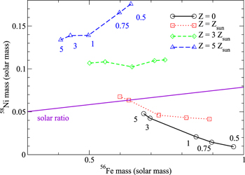
Figure 21. Similar to Figure 16, but for the mass of 58Ni against 56Fe. Notice that 56Fe is the decay product of 56Ni.
Download figure:
Standard image High-resolution image5. Discussion
5.1. Comparison with Previous Models
In the literature, multidimensional SN Ia simulations have been done. A trace back on multidimensional simulations can be as early as Mueller & Arnett (1982). At first sight, our work might appear to have overlap with previous works. This is not the case for several reasons.
- (1)
- (2)
- (3)There is not yet any systematic study of multidimensional SNe Ia in the literature, which spans the model parameter space while coupling with the updated microphysics. A revised and consistent study is therefore important to update the SN Ia modeling to be compatible with the rapidly growing observational data of SNe Ia.
- (4)Important updates in the microphysics have been found in the past decades, and there can be implications of these new updates to SN Ia simulations (Langanke & Martinez-Pinedo 2001; Seitenzahl et al. 2009). The changes of reaction rates, including the strong screening factor for 12C + 12C, can influence the explosion dynamics (e.g., Kitamura 2000) through, for example, the speed of the deflagration wave.
5.1.1. Travaglio et al.
Here we compare our results with some of the representative works in the literature that studied SNe Ia nucleosynthesis. In Travaglio et al. (2004), the first multidimensional simulation with nucleosynthesis is done using the tracer particle scheme. In their work, the pure turbulent deflagration with some initial flame bubbles is considered. The lack of detonation transition in this work has led to an overproduction of 54Fe and 58Ni and underproduction of α-chain isotopes. Their Ye is similar to ours from 0.462 to 0.500, but they observed an overproduction of Fe and Ni as persisted in the classical W7 model (Nomoto et al. 1984) as a result of the old weak interaction rates. Notice that the inclusion of DDT more likely further increases the production of 56Fe in the group of iron-peak elements.
5.1.2. Maeda et al.
In Maeda et al. (2010) the first large-scale study in nucleosynthesis is presented that is based on three hydrodynamics models. Their methodology is comparable to ours by including, for instance, NSE and electron capture. They have used a turbulent flame with similar prescriptions. They also have updated the weak interaction rate accordingly, but the NSE does not take nuclear screening into account.
In their work, three models are presented, including one pure turbulent deflagration model and two DDT models from a centered (C-DDT) and off-center (O-DDT) ignition kernel. Our model is the closest to their C-DDT model in terms of configuration and initial flame structure. Their (our) model shows a final kinetic energy and nuclear energy release at 9.6 × 1050 (1.27 × 1051) erg and 1.46 × 1051 (1.77 × 1051) erg, while the energy released by the nuclear reaction at DDT is 7.67 × 1050 (8.10 × 1050) in their (our) model. The energy difference is most likely contributed by our three-step schemes that the low-density matter (1–5) × 107 g cm−3 can still contribute to the energy budget as long as they can sustain the nuclear reactions. In terms of isotope distributions, more differences can be spotted.
They find IMEs such as 28Si at such a low velocity as ≈4 × 10³ km s−1, which is ∼30% lower than ours. They also report the presence of 16O with a mass fraction above 0.1 at 6 × 10³ km s−1, which is also 10% lower than our model. Although the 56Ni distribution is similar in both cases, they show a drop of 56Ni around 8 × 10³ km s−1 in their model, while for our case, depending on the viewing angle, 56Ni starts to drastically drop at (6–7) × 103 km s−1.
In terms of isotope abundances after decay, qualitative features of both models agree with each other. For example, we all have well-produced α-chain elements and iron-peak elements that increase with atomic number. The non-0.5 Ye isotope abundances are also similar, such that, for instance, the mass fractions of 51Cr, 59Cr, and 62Ni are higher than those for 50Cr, 58Fe, and 61Ni. But there exist some differences. For example, they observe a higher production of Ye < 0.5 also for IME. They have a higher 38Ar and 42Ca, with both of them well produced. Our models show both of them underproduced.
To make a further comparison of our results with their work, we plot in Figure 22 the speed of sound, the effective turbulent flame speed, and the laminar flame speed of the benchmark model as a function of time. The data points correspond to the mass-averaged value of the corresponding quantities from the mesh points that are undergoing carbon deflagration, as indicated by the level-set function. Detonation always wraps the deflagration front, which impedes the further propagation of the flame at late times. The flame speed survey stops when the flame is surrounded by detonation ash. In the figure we can see three quantities occupying a characteristic velocity range. The sound speed, which is the fastest among them, has a typical velocity of ∼104 km s−1. The effective turbulent flame is about one order of magnitude lower in speed, ∼103 km s−1. The laminar flame speed is the slowest in that at the beginning it is ∼102 km s−1, but it gradually drops as the star expands, to ∼1 km s−1 or lower. On the contrary, turbulence plays an important role to support the flame propagation at an almost-constant subsonic speed.

Figure 22. Speed of sound, laminar flame speed, and effective turbulent flame speed of the benchmark model. The error bar stands for the maximum and minimum velocities found in the simulation, and the data points are the mass-averaged results collected from meshes that are locally swept by the carbon deflagration.
Download figure:
Standard image High-resolution imageIn Figure 23 we plot the maximum temperature against maximum density of the thermodynamics history obtained from the tracer particles in the benchmark model. This figure can be compared with Figure 6 in their work. The particles can be separated into two groups, the group with ρmax > 109 g cm−3 and the group with ρmax ≤ 109 g cm−3. For the first group, it has an exponential relation between density and temperature where Tmax > 7 × 10⁹ K. This group corresponds to the particles burnt by carbon deflagration. For the second group, it can be seen that the particles have a range of Tmax from 3 × 10⁹ to 6 × 10⁹ K for a wide range of density. This corresponds to the particles being burnt by carbon detonation. The shock wave interaction due to multiple detonation ignition creates a wide spectrum in the ρmax–Tmax relation. Also, the matter density has dropped owing to expansion, where incomplete burning makes Tmax lower.

Figure 23. Maximum temperature against maximum density of the thermodynamics histories collected from the tracer particles from our benchmark model.
Download figure:
Standard image High-resolution imageIn Figure 24 we plot the final electron fraction against maximum density of the tracer particle thermodynamics histories. This plot is similar to Figure 9 in their work. For particles with a maximum density >109 g cm−3, it has a final Ye from 0.46 to 0.50. This corresponds to the particles that experienced carbon deflagration. For particles with a maximum density lower than 109 g cm−3, it has a final Ye = 0.5. These are the particles that experienced carbon detonation or incomplete burning, so that the particle does not have enough time to carry out electron capture before it cools down owing to star expansion. This figure can be compared with Figure 9 of Maeda et al. (2010). In their work, they have a wider distribution of ρmax for the same Ye. During deflagration, there is always a clear discontinuity between unburnt matter and burnt matter along the density contour. This creates a spectrum of time difference of each tracer particle to carry out electron capture. As a result, they have a wider range of ρmax for the same final Ye.

Figure 24. Similar to Figure 23, but for the final Ye against ρmax.
Download figure:
Standard image High-resolution image5.1.3. Krueger et al.
In Krueger et al. (2012), the effects of the central density are also studied in the range 1 × 10⁹–5 × 10⁹ g cm−3 for WD models with solar metallicity. The model configuration is very similar to ours, except for three points. First, in their 2D simulations, the turbulence–flame interaction is not implemented. The flame acceleration before DDT is assumed to be attributed solely to buoyancy stretching instead of turbulence stretching. Without the notation of subgrid scale turbulence strength, they parameterized the DDT criterion by the threshold density. Second, an adiabatic convective region is assumed for the initial WD as discussed in Section 2 for the initial model of Nomoto et al. (1984). A non-isothermal WD is used as the initial condition. Third, they assume the initial flame to be centered, but with combinations of sinusoidal perturbation controlled by random number generators. While increasing the central density, a few effects are observed: (1) An earlier DDT occurs. It varies from 1.5 s at ρc = 1 × 10⁹ g cm−3 to 0.8 s at ρc = 5 × 10⁹ g cm−3. (2) A lower 56Ni mass and also 56Ni/M(NSE) ratio occur. This shows that the flame takes a longer time to reach the DDT density, and there is more time for electron capture before the expansion of matter after detonation. Our models are consistent with theirs in the following ways. First, from Table 2, we observe an earlier DDT from 1.35 s down to 0.67 s from models 050-1-c3-1, 100-1-c3-1, 300-1-c3-1, and 500-1-c3-1. Second, the 56Ni mass drops from 0.89 to 0.59 M⊙.
5.1.4. Jackson et al.
In Jackson et al. (2010), the dependence on metallicity (namely, 22Ne) and the DDT density is explored. They carried out a series of 2D models similar to Krueger et al. (2012). We first review the metallicity effects. They carry out models with a metallicity from Z = 0.5 to 2.5 Z⊙. The NSE isotopes drop from an average of 0.85 to 0.70 M⊙. Our models agree with their trend that, by comparing with our models 300-0-c3-1, 300-1-c3-1, 300-3-c3-1, and 300-5-c3-1, the 56Ni yield drops significantly from 6.96 × 10⁻¹ M⊙ to 4.38 × 10⁻¹ M⊙, although there is a very mild increase in other NSE isotopes, such as 54Fe, 57Fe, and 58Ni. The drop of NSE isotopes is still dominated by the change of 56Ni.
Then, we compare the DDT density effects. They observed that when the DDT density is decreased from 107.5 to 107.1 g cm−3, the amount of NSE matter decreases from ≈1.2 to 1.0 M⊙, showing that more matter is burnt to NQSE matter, such as Si. This is consistent with our results. By comparing model 300-1-c3-1, Test A1, and Test A2, we see a decrease in the 56Ni mass from 0.627 to 0.450 M⊙ for the increase in the Karlovitz number, which is equivalent to the decease in the DDT density. At the same time, the 28Si mass increases from 0.235 to 0.324 M⊙. This suggests that the simplified nuclear burning scheme can still capture the essential nuclear reactions of a much larger network.
5.1.5. Seitenzahl et al.
Then, we shall compare with some representative 3D models. In Seitenzahl et al. (2011), the first 3D systematic study of nucleosynthesis is presented. The numerical modeling can also be traced back to that in Maeda et al. (2010). The DDT criteria are different in that the Karlovitz number is not directly included in this work. Instead, the turbulent velocity threshold and the flame surface area are the criteria for the trigger for DDT. In this work, the nucleosynthesis is analyzed based on the simplified energy scheme for hydrodynamics. They studied 12 models with density from 109 to 5.5 × 10⁹ g cm−3 in solar metallicity with off-center ignition kernels. Our benchmark model 3-1-c3-1 is the closet to their 0200 model at ρc = 2.9 × 10⁹ g cm−3 in the configuration. In terms of explosion energetic, their (our) model has a DDT time at 0.802 (0.779) s. The energy released by nuclear reaction at the transition time in their (our) model is about 8.10 × 1050 (8.03 × 1050) erg. The DDT density is 2.27 × 10⁷ (2.31 × 10⁷) g cm−3 in their (our) model. In terms of chemical abundance, their (our) model produces 0.752 (0.63) M⊙ of 56Ni. We also observe a similar amount of unburnt 16O at 0.06 M⊙. The difference in the 56Ni amount is most likely related to the initial flame. Our centered flame can have a stronger deflagration phase owing to its larger initial flame surface, which may further enhance the turbulence generation. Therefore, more fuel is being burnt in the deflagration phase and starts electron capture. As a result, the matter of lower electron fraction cannot produce as much 56Ni as in theirs.
Seitenzahl et al. (2013) presented the first large-scale study of nucleosynthesis in 3D models. This study concerns the effects of off-center ignition kernels on the nucleosynthesis. The methodology is still comparable to Seitenzahl et al. (2011), but with an extra requirement on the timescale that the DDT criteria should be satisfied for at least half an eddy turnover time. Our benchmark model can be compared to their N100 model, which is also selected to be representative of the typical SN Ia model, which is characterized by an initial flame of 100 flame bubbles with a size of 10 km and a mean radius of 60 km from center. They presented 14 models of different ignition kernels at solar metallicity and one model with metallicity from 0.01 Z⊙ to solar metallicity. In terms of spatial distribution, their N100 model shows that 56Ni is produced from 0 to 9 × 10³ km s−1, which is significantly higher than ours at (6–7) × 103 km s−1. 58Ni has also a similar distribution to 56Ni, but at a lower mass fraction below 0.1. 58Ni in our model also has a lower mass fraction but has some peaks at about 0.1, on the contrary. The IME distribution is comparable to ours in that both models show signatures of IME starting from (3–4) × 103 km s−1 and IMEs become the dominant isotopes at a velocity above (6–7) × 103 km s−1. In terms of mass fraction, our model is also very close to theirs qualitatively. For example, both models show the iron-peak elements peaked at their isotopes of highest electron fraction. A jump in the mass fraction of 59Fe and 62Ni is also observed, and their values but our models predict both isotopes with higher mass fractions. One major difference is that our models predict a drop in 53Cr compared to other Cr isotopes, but its production is boosted in their model.
We compare the central density dependence with the models in Seitenzahl et al. (2013). In our models, 050-1-c3-1 100-1-c3-1, 300-1-c3-1, and 500-1-c3-1 form the series of models with the same configuration but different central densities from 5 × 10⁸ g cm−3 to 5 × 10⁹ g cm−3. In Seitenzahl et al. (2013), N100L, N100, and N100H are the series of models of similar properties, but for central density from 1 × 10⁹ g cm−3 to 5.5 × 10⁹ g cm−3. In their models, an increase of central density leads to the following trends:
- 1.The yields of IMEs decrease. This can be observed from the variations of 28Si (32S) in that it drops from 3.55 × 10⁻¹ (1.38 × 10⁻¹) to 2.12 × 10⁻¹ (8.55 × 10⁻²) M⊙.
- 2.More 56Ni is produced. This can be observed by the yield growing from 5.32 × 10⁻¹ to 6.94 × 10⁻¹ M⊙.
- 3.A significant increase of neutron-rich isotopes, including 50Ti, 54Cr, 58Fe, and so on. The yielded mass for 50Ti (58Fe) increases from 6.88 × 10⁻¹⁰ (1.27 × 10⁻⁷) to 1.02 × 10⁻⁴ (5.29 × 10⁻³) M⊙.
Then we compare their results with our models.
- 1.In our models when central density increases, yields of IMEs increase. There is an increase of 28Si (32S) from 2.26 × 10⁻¹ (1.24 × 10⁻¹) to 2.70 × 10⁻¹ (1.8 × 10⁻¹) M⊙.
- 2.The 56Ni mass decreases. It drops from 7.46 × 10⁻¹ to 5.94 × 10⁻¹ M⊙.
- 3.Masses of neutron-rich isotopes increase. The 50Ti (54Cr) yield also increases from 6.22 × 10⁻¹⁰ (1.91 × 10⁻⁷) to 5.21 × 10⁻⁴ (1.42 × 10⁻²) M⊙. The difference in the first two trends shows that the center flame can behave differently from the off-center flame. Also, the dimensionality plays a role.
We remind the reader that the bubble configuration in our models corresponds to the ring in the 3D realization. In lower dimensionality, the smaller number of degrees of freedom tends to enhance the radial motion of the flame, thus boosting the burning. In our models, when central density increases, the centered flame can propagate faster because the thermalized core sustains the flame to move outward. On the other hand, the off-centered flame may experience stronger suppression after electron capture. The flame may take a longer time to reach the low-density region for triggering DDT, while burning more matter simultaneously. On the other hand, the comparable neutron-rich isotopes show that our calculation has a consistent electron capture rate with their works.
We compare the metallicity dependence with the models in Seitenzahl et al. (2013). In Seitenzahl et al. (2013), models N100, N100-Z0.1, and N100-Z0.01 form another series that studies the effects of varying metallicity. We compare their results with our models 300-0-c3-1, 300-1-c3-1, 300-3-c3-1, and 300-5-c3-1. In their models when metallicity increases, two trends can be observed: (1) 55Mn increases from 7.84 × 10⁻³ M⊙ to 9.29 × 10⁻³ M⊙, and (2) masses of isotopes with electron fraction close to 0.5 increase, such as 54Fe and 58Ni. An increase of yield from 6.62 × 10⁻² (5.01 × 10⁻²) M⊙ to 9.94 × 10⁻² (6.90 × 10⁻²) M⊙ can be observed for 54Fe (58Ni). Our models also show the similar trend that 55Mn grows from 7.25 × 10⁻³ to 9.55 × 10⁻³, while 54Fe (58Ni) grows from 8.48 × 10⁻² (4.29 × 10⁻²) M⊙ to 1.60 × 10⁻¹ (6.35 × 10⁻²) M⊙. This shows that our treatment of metallicity using 22Ne as a proxy is consistent with their results.
5.2. Comments on the Limitation of 2D Models
In this article we perform a number of 2D SN Ia simulations with post-process nucleosynthesis, from which we extract the influence of model parameters on the chemical abundances. Our model can represent a WD where the fluid motion inside the WD preserves symmetry, such that the center remains the most probable location for the first flame to occur, and the initial flame can have sufficient time to develop before being brought away from center by convection. However, in general the 3D SN Ia models may provide higher flexibility to account for the diversity of the WD environment prior to explosion. Here we briefly describe the shortcoming of 2D models compared to 3D ones.
One of the shortcomings in 2D simulations are the boundary effects. Due to the assumed rotational symmetry, no bubble can be naturally constructed as the initial flame, where the flame bubble is often used as initial configurations (Roepke & Hillebrandt 2005) for SN Ia simulation during the early phase of laminar flame propagation, when hydrodynamics instabilities are not strong enough to distort the flame structure. As shown in Seitenzahl et al. (2011), how many bubbles there are at the beginning is one of the primary parameters in controlling the explosion strength. One of the possible methods to model the flame bubble in a 2D model is by using the one-bubble case, where a spherical flame is placed along the axis of rotational symmetry. However, we remark that this model cannot be compared completely with the counterpart in the 3D model. Due to the reflective boundary along the symmetry axis, motion close to the boundaries tends to be enhanced. For example, the symmetry of an initially spherical-shaped bubble may quickly be destroyed by the Rayleigh–Taylor instabilities. Therefore, in the context of SNe Ia for the one-bubble configuration, where turbulence is believed to play a major role in flame propagation, this strong boundary flow may provide unrealistic enhancement of turbulence production, which overestimates the flame propagation, as well as the transition time. These effects will entangle with the true hydrodynamics effects. This makes the extraction of model parameter effects difficult.
Second, the symmetry boundary creates hot spots after detonation. As shown in Figure 1, after the detonation is developed, the spherical detonation wave spreads rapidly and collides with the symmetry axis. The reflected shock wave further interacts with the incoming shock, where intersection of the shock wave compresses the matter in between and creates the hot spot. However, the shock–boundary interaction is most likely to occur in 2D models. In a 3D model, the use of a randomized bubble configuration makes the shock waves colliding with each other less likely. Such collisions create zones that experience a short period of time in comparatively high density and temperature. The temperature can be much higher than that after laminar deflagration or the detonation wave has passed through. Therefore, in nucleosynthesis it is possible that such a temperature fluctuation may lead to a boost in heavy isotope production, which might not be realized in 3D models.
6. Summary
In the present paper, we present 2D hydrodynamics simulations of near-Chandrasekhar-mass WD models for SNe Ia using the turbulent deflagration model with DDT. By calculating 41 models, we perform a parameter survey to study the effects of the initial central density (i.e., WD mass), metallicity, flame shape, and detonation transition criteria, as well as a turbulent flame formula for a much wider parameter space than earlier studies. The final isotopic abundances of 11C to 91Tc in these simulations are obtained by post-process nucleosynthesis calculation. The parameter survey includes SN Ia models with the central density from 5 × 10⁸ g cm−3 to 5 × 10⁹ g cm−3 (WD masses of 1.30–1.38 M⊙), a metallicity from 0 to 5 Z⊙, a C/O mass ratio from 0.3 to 1.0, and ignition kernels, including centered and off-centered. The yield tables of 25 elements from carbon to zinc for a total of 41 models are computed. We examine the possible effects of Ye mixing and find that it is important to nucleosynthesis. The results are compared with the solar composition to derive constraints on each model parameter. We also compare our models with some well-observed SNe Ia, including SN 2011fe, SN 2012cg, and the SN remnant 3C 397. The possible SN progenitors, based on the abundance of 55Mn, 57Fe, and 58Ni, are suggested. We have also carried out a similar survey for the pure turbulent deflagration model and pure carbon detonation model. The connection between the pure turbulent deflagration model and the subluminous SNe Iax is discussed.
We find that dependencies of the nucleosynthesis yields on the metallicity and the central density (WD mass) are large. For comparisons with the observed abundance patterns of SNe Ia and their remnants to constrain the explosion model and also for the application to the galactic chemical evolution modeling, these dependencies on metallicity and WD mass should be taken into account. For this purpose, we present tables of the nucleosynthesis yields of 12C to 70Zn, as well as the major radioactive isotopes for 33 models. For yields from core-collapse SNe, see Nomoto et al. (2013).3
Our calculations may be applied to verify the validity of input physics from observational data. Recent observations of SN Ia remnants and the luminosity evolution from the late-time light curves of SNe Ia have shown possibilities to understand the SN physics through the abundance pattern of certain representative isotopes. In future, the growing number of these kinds of objects may provide us the necessary constraints on each of the model parameters.
This work has been supported by the World Premier International Research Center Initiative (WPI Initiative), MEXT, Japan, and JSPS KAKENHI grant nos. JP26400222, JP16H02168, and JP17K05382, and the Endowed Research Unit (Dark Side of the Universe) by Hamamatsu Photonics K.K. We thank F. X. Timmes for his open-source microphysics algorithm including the Helmholtz equation-of-state subroutine, the torch nuclear reaction network designed for an arbitrary choices of isotopes, the seven-isotope nuclear reaction network, and the galactic chemical evolution code. S.C.L. thanks S. Blinnikov, M. Ishigaki, and C. Kobayashi for their insightful comments. We also thank T. Plewa for a discussion that helped us a lot in reviewing the methodology of SN Ia modeling.
Appendix A: Review of Our Hydrodynamics Code
Here we briefly review the structure of the hydrodynamics code and then present the new updates and changes incorporated in this article. For implementation details, code tests, and applications to pure turbulent deflagration and DDT models, refer to Leung et al. (2015b). The code has been used to standard SN simulations and nucleosynthesis (Leung et al. 2015a; Leung & Nomoto 2017).
The code is an extension of the previous version of the hydrodynamics code that solves the 2D Euler equations in cylindrical coordinates with subgrid turbulence and a moving grid. Following the carbon deflagration and detonation, the explosion unbinds the WD. The WD quickly expands and the matter cools down so that all thermal nuclear reactions end. In order to understand the final nucleosynthesis, we keep track of the fluid motion until matter reaches homologous expansion. Using the moving-mesh algorithm (Roepke 2005; Roepke & Hillebrandt 2005), the grid size is a time-dependent variable that varies with the WD. In particular, we make sure that the matter of WD is accommodated inside the simulation box throughout the simulation. To do so, we assume that the grid boundary carries out a homologous expansion, namely,  . Here,
  and R are the spherical distance from the origin and the radius of the star, respectively. vf is the magnitude of the expanding grid velocity, which is assumed to be equal to or slightly larger than the surface velocity of the WD. The Euler equations are then rewritten as

where ρ, v, pNM, q, and τ are the mass density, velocity vector including the r and z directions, pressure, and total energy density of the baryonic matter, respectively. The total energy density includes both the thermal and kinetic components  , where
  is the specific internal energy density. The specific turbulence energy density
  /2 corresponds to the velocity fluctuations
  , where the energy exchange between τ and q is given by
The gravitational potential Φ is determined by the Poisson equation

We use the fifth-order weighted essentially nonoscillating scheme for the spatial discretization and the five-step third-order non-strong-stability-preserving Runge–Kutta scheme for the time discretization. We use the successive over-relaxation method with Gauss–Seidel iterations to solve the gravitational potential. The boundary is fixed to be  . To find the pressure and internal energy, we use the Helmholtz equation of state (Timmes & Swesty 1999), which provide these two quantities as a function of density, temperature, mean atomic mass
  , and mean atomic number
  .
.
In this paper, in contrast to Leung et al. (2015b), we try to represent the chemical composition of the matter by seven isotopes: 4He, 12C, 16O, 20Ne, 24Mg, 28Si, and 56Ni (Timmes et al. 2000). We choose to reduce the representative isotope number because in the hydrodynamics the chemical abundance is mainly responsible for providing the mean atomic mass and mean atomic number; therefore, a network that can describe C burning to Ni and photodisintegration into α-particles is sufficient to describe most energy generation and absorption processes. The detailed chemical abundance is obtained from a much larger network to the post-processing nucleosynthesis (see Appendix A.4 for further details).
We use a three-step burning to characterize the nuclear reactions (Khokhlov 1991a; Townsley et al. 2002). These three reactions capture the essential nuclear burning phase that occurred in C deflagration and detonation. They include the C burning, NQSE burning, and NSE burning. In terms of the isotopes we have, they are

The choices of these representative isotopes are as follows. For the first step, C is the earliest and fastest isotope to be burned in the flame and detonation. It provides the first energy source for the coming O burning and Si burning. Si is used as the ash in the second set of reactions because Si can be sustained for a comparatively long time compared to other IMEs, such as Mg or S, before Fe-group elements emerge. It therefore provides a good approximation to the progress of NQSE burning. At last, Ni and α are the product of NSE burning as commonly used in the literature (Reinecke et al. 1999a, 2002). This represents the end point of the α-chain network plus the photodisintegration effects at high temperature.
A.1. Nuclear Reactions and Flame Capturing Scheme
The change of the NSE composition is assumed to take place as long as the local temperature T > 5 × 10⁹ K. The NSE composition is prepared in tabular form with XNSE = XNSE(ρ, T, Ye). The table is prepared similarly to Seitenzahl et al. (2009), where the corresponding binding energy and composition are computed beforehand. After the hydrodynamics substep, the trial internal energy  is obtained. Nuclear energy due to composition changes is included, and the new temperature and internal energy at step n + 1 are solved iteratively such that they satisfy

ΔEB is the change of binding energy, where both the initial and final states are assumed to be in NSE, which are functions of the local density, temperature, and electron fraction.
To determine the energy release by carbon deflagration and detonation, we use the level-set method (Reinecke et al. 1999b) to describe the front geometry. We implement the passive version of the level-set method owing to the known numerical difficulty in reconstructing the exact thermodynamics state when there is numerical noise or error (Reinecke et al. 1999b). This method introduces the scalar G, whose zero-contour represents the front surface and evolves as

 and
and  are the fluid velocity and the front propagation speed, respectively, where Gi can represent either the deflagration or detonation front by the notation i = flame or deton. We use operator splitting to solve the equation. The advection is handled by the WENO scheme, while the flame propagation is obtained by solving
  . Notice that for the ideal case where
  exactly,

For deflagration, we use the laminar flame speed formula reported in Timmes & Woosley (1992) with the turbulent flame speed relation (Pocheau 1994; Schmidt et al. 2006)
and
We use the standard value Ct = 4/3 in this article. We notice that Equation (12) is an empirical model based on renormalization and energy conservation, which may not be different from the actual turbulence–flame interaction. We notice that besides this formula, in the literature there are also other turbulence–flame speed formulae derived from some direct numerical experiments (see, e.g., Hicks 2015), where the empirical relation between the effective flame speed under the influence of turbulent velocity fluctuation is studied by direct numerical simulations. They find that the modified model
and the best-fit model
can represent the turbulence–flame interaction for their simulations.
In every time step, after we have updated the propagation part of the level-set function, we increase the internal energy according to the area swept by the deflagration front. The corresponding 12C is burnt into 24Mg. The carbon is assumed to be completely burnt independent of density.
A similar procedure is prepared for detonation. Another scalar field is used to represent the geometry of the detonation front, where the advection and propagation are treated separately. The detonation velocity for matter with density larger than 2 × 10⁷ g cm−3 is obtained by solving the detonation wave structure as described in Sharpe (1999). The detonation for the matter with a density below that is assumed to propagate in the form of Chapman–Jouget detonation. Similar to the deflagration, the area swept by the detonation front is assumed to be completely burnt, which means that all 12C is converted to 24Mg within that region, and the corresponding binding energy change is added to the internal energy.
A.2. Criteria for DDT
DDT assumes that the deflagration develops into detonation (Khokhlov 1991b) when the flame enters the distributed regime, where the heat conduction rate owing to turbulence diffusion becomes comparable to the consumption of fuel. This process creates the detonation seed by the Zeldovich gradient mechanism (Khokhlov et al. 1997a). It has been shown in numerical experiments that the detonation can be triggered through the shock–flame interaction (Khokhlov et al. 1997b), which creates hot spots in shock-tube experiments, and through the unsteady turbulent flame evolution (Poludenko et al. 2011) in an unconfined medium. However, there are arguments on the feasibility of this model based on arguments of whether turbulence can sustain the necessary strong velocity fluctuation (∼103 km s−1; Lisewski et al. 2000; Roepke et al. 2006). This model has been frequently applied to SN Ia explosion in both 1D models (Nomoto et al. 1984; Khokhlov 1991a, 1991c; Blondin et al. 2013) and multidimensional models (Gamezo et al. 2004, 2005; lolombek & Niemeyer 2005; Blondin et al. 2011; Seitenzahl et al. 2013). These models can show healthy explosions with a variety of nickel yield to explain the observed SN Ia diversity, while producing chemical abundance compatible with observations.
In our calculation, at the end of each step, we compare the eddy turnover scale with the flame width, i.e., the Karlovitz number Ka. Here we define the Karlovitz number as (Niemeyer et al. 1995) the ratio of laminar flame width lflame to the eddy size lturb. To determine the flame width, we use the deflagration wave structure taken from Timmes & Woosley (1992) as a function of density. In general, the flame becomes wider in its size when density decreases. It can be as thin as ∼10−5 cm at high density = 1010 g cm−3, but it can be as thick as 101 cm at low density = 107 g cm−3 for matter with X(12C) = X(16O) =0.5. For the eddy size, one can use the Kolmogorov scaling relation v(l) = v(L) (l/L)1/3. The Gibb's length scale (Niemeyer et al. 1995) is given by
Notice that the eddy size is not directly used because below Gibb's length scale anisotropy is always polished out by the flame propagation because of the faster burning at cusp.
To determine whether detonation can start or not at the end of each step, we check for grids that satisfy Ka = 1. A detonation seed of a ring with a radius of 15 km is created around the grids that fulfill this condition of Ka = 1. We remark that, in the literature, there is not yet any conclusive study that can pinpoint the exact detonation transition condition. A recent study of Poludenko et al. (2011) has found that Ka > 100 is needed for a spontaneous detonation for premixed H2-air flame. In the hydrodynamics simulations, we also perform models with different Ka as the detonation transition criteria.
A.3. Weak Interactions
To study the effects of density, electron capture in NSE regions due to weak interaction cannot be neglected. We include this process by introducing the electron fraction Ye, which can be transported by the fluid flow, namely,

 is the electron capture rate of matter in NSE as functions of density, temperature, and electron capture, which is derived from the table presented in Seitenzahl et al. (2009). The change of local internal energy by the electron capture is given by

Here μi (e, p or n) represents the chemical potential of electrons, protons, and neutrons, respectively.  is the energy loss by the escaped neutrino during electron capture.
We remark that this small network does not contain any isotope that is mainly produced by NSE at Ye < 0.50. To incorporate the physics of electron capture into hydrodynamics, we define the effective atomic number  , such that the pressure and internal energy are given by
  and
and  , respectively. The reduced atomic number is to mimic the reduction of electron fraction for the same amount of nucleons.
A.4. Post-processing Nucleosynthesis and Updates
We use the tracer particle scheme (Travaglio et al. 2004; Seitenzahl et al. 2010) for the post-process nucleosynthesis. This scheme allocates some massless particles that follow the fluid motion during the hydrodynamics simulations. The thermodynamics history, including their local densities, temperature, positions, and velocities, of the tracer particles are recorded. The nuclear reaction history is then reconstructed. Following the suggestion from Seitenzahl et al. (2010), the number of tracers is fixed to be 1602 to ensure the convergence of particles. In the post-processing stage, we use the much larger 495-isotope network, which contains elements from hydrogen to technetium. In Table 12 we tabulate the isotopes included in the calculations.
Table 11. Explosion Energetic and Global Nucleosynthesis Quantities of the Pure Turbulent Deflagration Models
| Model | Enuc | Etot | Mej | Mb | Mburn |

|
M(IGE) | M(IME) |

|
Mej(IGE) | Mej(IME) |
|---|---|---|---|---|---|---|---|---|---|---|---|
| 050-1-c3-1P | 5.0 | 1.1 | 0.40 | 0.90 | 0.40 | 0.21 | 0.33 | 0.07 | 2.20 × 10⁻² | 2.40 × 10⁻² | 1.00 × 10⁻² |
| 075-1-c3-1P | 6.0 | 1.8 | 0.22 | 1.09 | 0.46 | 0.24 | 0.30 | 0.16 | 8.14 × 10⁻³ | 8.89 × 10⁻³ | 5.21 × 10⁻³ |
| 100-1-c3-1P | 6.7 | 2.2 | 0.37 | 0.96 | 0.51 | 0.26 | 0.35 | 0.16 | 3.08 × 10⁻² | 3.36 × 10⁻² | 1.04 × 10⁻² |
| 300-1-c3-1P | 9.5 | 4.5 | 0.55 | 0.82 | 0.69 | 0.31 | 0.39 | 0.30 | 0.10 | 0.14 | 4.28 × 10⁻² |
| 500-1-c3-1P | 11.1 | 5.9 | 1.10 | 0.28 | 0.79 | 0.32 | 0.64 | 0.15 | 0.29 | 0.37 | 7.12 × 10⁻² |
Note. Mej and Mb are the ejecta and remnant mass, respectively, of the SNe Ia in these models. Mej (Mb) is the total mass where the fluid elements have a velocity above (below) the escape velocity. Mburn is the ash mass at the end of simulations. M(IGE) and M(IME) are the iron-peak elements and IMEs, respectively, derived after all short-life radioactive isotopes have decayed.  , Mej(IGE), and Mej(IME) are the masses of 56Ni, iron-peak elements, and IMEs, respectively, derived after all short-life radioactive isotopes have decayed in the ejecta. All masses are in units of M⊙. Enuc and Etot are the energy released by nuclear reaction and the asymptotic energy at the end of simulations, respectively, in units of 1050 erg.
Download table as: ASCIITypeset image
Table 12. Isotope Network Used for the Post-process Nucleosynthesis
| Element | Z | Amin | Amax |
|---|---|---|---|
| Hydrogen | 1 | 1 | 3 |
| Helium | 2 | 3 | 4 |
| Lithium | 3 | 6 | 7 |
| Beryllium | 4 | 7 | 9 |
| Boron | 5 | 8 | 11 |
| Carbon | 6 | 11 | 14 |
| Nitrogen | 7 | 12 | 15 |
| Oxygen | 8 | 14 | 19 |
| Fluorine | 9 | 17 | 21 |
| Neon | 10 | 17 | 24 |
| Sodium | 11 | 19 | 27 |
| Magnesium | 12 | 20 | 29 |
| Aluminum | 13 | 22 | 31 |
| Silicon | 14 | 23 | 34 |
| Phosphorous | 15 | 27 | 38 |
| Sulfur | 16 | 28 | 42 |
| Chlorine | 17 | 31 | 45 |
| Argon | 18 | 32 | 46 |
| Potassium | 19 | 35 | 49 |
| Calcium | 20 | 36 | 49 |
| Scandium | 21 | 40 | 51 |
| Titanium | 22 | 41 | 53 |
| Vanadium | 23 | 43 | 55 |
| Chromium | 24 | 44 | 59 |
| Manganese | 25 | 46 | 61 |
| Iron | 26 | 47 | 66 |
| Cobalt | 27 | 50 | 67 |
| Nickel | 28 | 51 | 68 |
| Copper | 29 | 55 | 69 |
| Zinc | 30 | 57 | 72 |
| Gallium | 31 | 59 | 75 |
| Germanium | 32 | 62 | 78 |
| Arsenic | 33 | 65 | 79 |
| Selenium | 34 | 67 | 83 |
| Bromine | 35 | 68 | 83 |
| Krypton | 36 | 69 | 87 |
| Rubidium | 37 | 73 | 85 |
| Strontium | 38 | 74 | 84 |
| Yttrium | 39 | 77 | 87 |
| Zirconium | 40 | 78 | 90 |
| Niobium | 41 | 82 | 90 |
| Molybdenum | 42 | 83 | 90 |
| Technetium | 43 | 89 | 91 |
Download table as: ASCIITypeset image
We use the Torch subroutine (Timmes 1999) to solve the system of nuclear reaction equations. The subroutine solves the stiff system of ordinary differential equations obtained from the chosen nuclear reaction network with the semi-implicit scheme. The nuclear reaction rates are taken from Fowler et al. (1967), Thielemann et al. (1987), and updated values from Rauscher & Thielemann (2009). The weak interaction takes the rates from Fuller et al. (1982) with updated values from Langanke & Martinez-Pinedo (2001). The screening function is taken from Kitamura (2000), which overwrites the default choice of the analytic formulae given in Alastuey & Jancovici (1978). In calculating the reaction rates, the faster rates among (α, p), (p, γ), and (α, γ) are chosen as the preferred nuclear reactions.
We noticed that in Townsley et al. (2016), they reported that the post-process scheme requires a reconstruction for the thickened flame in order to produce an accurate temperature–density history. We remarked that such treatment is less important for the level-set formalism. First, in the advective-diffusive-reactive (ADR) flame formalism, the algorithm estimates the injection of the C-burning energy by the burning variable ϕ1 where ϕ1 [0,1]. Cells with ϕ1 (0,1) stand for those actively burning carbon. Due to numerical diffusion and the inherent diffusion scheme, cells that are carrying out carbon burning are always dispersed into a few grids in each direction. This phenomenon also appears even in high density, where the real flame width can be as thin as ∼cm. This creates a problem that the temperature growth can be underestimated from the actual temperature evolution of the tracer particles and from the expected temperature evolution if the flame is treated as the thin flame, which does not experience the same smearing effect. To ameliorate the dispersion effect, in Townsley et al. (2016) the reconstruction process is proposed. Instead of using the temperature of the Eulerian grid, the exact position of the deflagration is reconstructed by the composition. The temperature of the tracer particle is interpolated by comparing the flame position and the particle position. On the other hand, in the level-set formalism, the flame geometry in a 2D simulation is treated as a 1D line provided by the zero-contour of the scalar field. The injection of energy by the flame is always localized and is not smeared. Thus, the temperature in the Eulerian grid can consistently follow the average temperature of that fluid element when the C-deflagration sweeps across. Notice that the temperature representation can be inaccurate at very low density <107 g cm−3, where the flame width extends to be comparable to the typical mesh size (∼km). In that case, the ADR formalism provides a more accurate description of the energy injection. But this feature will be less important for the study of nucleosynthesis since the important yields, in particular the iron-peak elements, are handled in the high density ρ > 5 × 10⁷ g cm−3, where the thin flame treatment is a good approximation to the actual energy injection.
Appendix B: Hydrodynamics of the Benchmark Model
In the main text we have described the principle ideas about the benchmark model through its energy, luminosity, and flame structure. In this section we further describe the hydrodynamics evolution of the benchmark models by its density, temperature, and velocity at different times. In Figures 25 and 26 we plot the density, temperature, and velocity profiles along the rotation axis and along the diagonal direction, respectively. Profiles at the beginning, at 0.25, 0.50, and 0.75 s, at DDT, and at 0.05 s after DDT are chosen.

Figure 25. Density (top left panel), temperature (top right panel), and velocity (bottom panel) profiles of the benchmark model along the rotation axis at the beginning, at 0.25, 0.50, and 0.75 s, at DDT, and at 0.05 s after DDT.
Download figure:
Standard image High-resolution image
Figure 26. Similar to Figure 25, but along the diagonal direction.
Download figure:
Standard image High-resolution imageAlong the rotation axis, the flame propagates more slowly because the c3 flame has set this direction to be a trough of the flame. At the beginning, the turbulent flame can efficiently burn the surrounding matter of the core, making the core matter expand. Within the first 0.75 s, the central density has dropped by a factor of ∼10. The slow flame creates a small density contrast, which grows from a few percent at a density of 109 g cm−3 to a few tens of percent at a density of 108 g cm−3. On the other hand, due to the subsonic propagation, the temperature profile appears to be very smooth within the ash region. A small temperature bump can be seen just outside the deflagration front, which is because the isobaric condition is not perfectly implemented at the beginning when the flame is implanted. At last, the velocity profile shows more interesting features along the rotation axis. At the beginning, there is a nonzero inflow of matter outside the flame front, which is related to the Rayleigh–Taylor instabilities. The "finger" structure allows the flame along the "finger" to propagate faster than the trough. As a result, the cold fuel is repelled from the "finger" to the nearby trough, which then hinders the propagation of the flame. At the beginning, when the star is mostly static, such effects can be most easily observed. Following the DDT, as noticed in Figure 1, the detonation wave creates disturbance along the axis because of the shock–boundary interaction. There are more wiggles in the density profiles. From the velocity profile, it also shows that the inflow stops, but the flame front along the axis remains partially suppressed by the nearby flow.
Along the diagonal direction, the evolution becomes much cleaner since this is along the "finger" structure of the flame, whose propagation is more pronounced owing to its geometry. The density evolution is almost comparable to the typical 1D models, where the flame creates the clean-cut discontinuity. The density contrast grows with time. The temperature profiles are also smooth compared to the previous plot. Again, a small bump of temperature can be observed, but its temperature is much below the ignition temperature of the fuel. At last, the velocity profiles show that the homologous expansion quickly develops after DDT. Before DDT, the ash shares a comparable velocity with some bumps near the surface similar to the temperature profiles.
Appendix C: Study of Minimum Temperature on the Flame Propagation
In the main text we have mentioned that the numerical scheme of how deflagration inputs energy is not completely quiet so that the numerically resolved flame front can be different from the wave form solved analytically. Thus, just outside the flame front there can be disturbance in the form of a sound wave that mildly heats up the matter. However, it is unclear whether the nonzero sound wave can affect the propagation of the flame and also cause unrealistic heating of the matter, which may be misinterpreted by the post-processing nucleosynthesis. In this section we discuss the effects on the flame propagation to the temperature profiles and luminosity. To analyze this effect, we present three benchmark models but with different absolute minimum temperature Tmin. This temperature corresponds to the minimum temperature allowed in the simulation. When the EOS solvers convert the internal energy to the temperature for a given density and composition, if the solved temperature is below Tmin, the temperature is reset to Tmin with its adjusted accordingly. To isolate this effect, we pick Tmin = 105, 106, and 107 K, respectively, to check how large the difference can be.
In Figure 27 we plot the temperature profiles of the three models at 0.3 and 0.6 s and the corresponding time-integrated energy production, respectively. We take the directions along the rotation axis and along the diagonal for sampling. At 0.3 s, we can see that along the axis for a high Tmin (e.g., 107 K) there is some temperature wave structure just outside the deflagration front. But the transition from fuel to ash is smooth when a low Tmin (e.g., 105 K) is chosen. However, the bump structure persists along the diagonal. The difference in temperature profile can extend from 30 to 50 km depending on the flame structure. The temperature profiles beyond are the same. At t = 0.6 s, where the flame front reaches a lower density, the choice of Tmin has more influence on the temperature profile. Along the rotation axis, for low Tmin (≤106 K) the bump structure can be smoothly evolved where a spike at 820 km can be preserved. For larger Tmin, the spike cannot be smoothly produced when the temperature reaches below the limit. The size of this structure increases when Tmin becomes small. Again, the temperature profiles are independent of the choice of Tmin behind the flame front (800 [900] km along the rotation axis [diagonal]) and beyond the flame front (≈1000 km for both directions). Along the diagonal direction, similar observations appear so that as Tmin = 107 K, the structure beyond the deflagration front cannot be fully captured. For lower temperature, the structure can be preserved when the temperature navigates around Tmin.

Figure 27. Top left panel: temperature profiles of the benchmark model along the rotation axis and diagonal direction at t = 0.3 s. Different choices of Tmin from 105 to 107 K are chosen. Top right panel: similar to the top left panel, but at t = 0.6 s. Bottom panel: time-integrated nuclear energy production for the three models.
Download figure:
Standard image High-resolution imageIt can be seen that the choice of Tmin can lead to some different temperature distributions just outside the flame front. However, we remark that, despite all the differences, from the bottom panel of Figure 27 we can see that the actual effects of the Tmin choice are very small. At t = 0.1 s, the three models show a deviation from each other, where the one with Tmin = 107 K shows a lower integrated nuclear energy of about a few percent, meaning that its flame propagation is a bit slower than the other case. But this effect is compensated at around t = 0.5 s, when the deflagration becomes large such that the small-scale details become less important. From this we observe that the choice of Tmin will affect the deflagration profile just outside the ash, but it has much smaller global effects compared to other numerical uncertainties.
Appendix D: Effects of Updated Electron Capture Rates in 1D Models W7 and WDD2
In the present modeling, we use input physics as described in Section 2.2. In view of still-existing uncertainties involved in input physics, we examine how the updated electron capture rates affect the nucleosynthesis yields in 1D Chandrasekhar-mass models: PTD model W7 (Nomoto et al. 1984; Thielemann et al. 1986) and DDT model WDD2 (Iwamoto et al. 1999).
These two models have successfully described the typical abundance distribution of SNe Ia and its coherence with the solar abundance. However, some problems have been noticed in these two models. For example, stable Ni is overproduced to make [Ni/Fe] ∼ 0.6 in W7, and Cr is overproduced in WDD2.
Due to the availability of new electron capture rates, where the rates for iron-peak elements are in general lower, it is interesting to see whether the overproduction problems in W7 and WDD2 can be alleviated. This is also a study of how the abundance ratios among iron-peak elements depend on electron capture rates and possibly other nuclear reaction rates in view of still-existing uncertainties of these rates (see also Mori et al. 2016).
Thus, post-process nucleosynthesis in W7 and WDD2 is recalculated by using our updated nuclear reaction network. In new W7 and WDD2, electron capture rates by Langanke & Martinez-Pinedo (2001) are applied.
In Figure 28 we plot the abundance distribution of the major isotopes in W7 and WDD2 against the mass coordinate.

Figure 28. Mass fraction distribution of major isotopes for W7 (left panel) and WDD2 (right panel).
Download figure:
Standard image High-resolution imageIn W7, the turbulent deflagration produces a layered structure in the explosion ejecta. In the innermost part, electron capture leads to the production of low-Ye isotopes such as 56Fe and 54Fe. 58Ni is also abundantly produced at a similar site to 54Fe. Then at ∼0.2 M⊙ 56Ni becomes the most abundant isotope, which extends up to ∼0.9 M⊙ (here Mr is the Lagrangian mass coordinate). At the same time, 55Co, which is the parent nucleus of 55Mn, is also produced at Mr = 0.2–0.7 M⊙. Beyond 0.9 M⊙, IMEs (including Si, S, Ar, and Ca) are the major isotopes in the middle layer. At Mr = 1.1–1.3 M⊙ matter is 16O rich, signifying that nuclear burning has become incomplete as the flame reaches the low-density zone. Above M ∼ 1.3 M⊙ no nuclear reaction occurs and the matter is pure 12C and 16O (with 22Ne).
In WDD2, DDT produces two distinct layers in the ejecta, the inner (outer) one a product of deflagration (detonation). In the innermost 0.3 M⊙, where matter is burnt by deflagration, the structure is similar to W7 with a low-Ye isotope in the core, an outer core with 56Ni, IMEs in the outer envelope, and 16O rich near the boundary of the deflagration zone. Then in the detonation zone, 56Ni is the dominant species that extends up to 0.9 M⊙. Besides 56Ni, 57Ni and 58Ni are also produced from M(r) = 0.3 to 0.5 M⊙. Then 54Fe and 55Co are produced in the ejecta. The matter becomes 28Si rich at Mr = 0.9–1.2 M⊙ and 16O rich at Mr > 1.2 M⊙.
In Figure 29, we plot the scaled mass fraction for new W7 and WDD2 in the left and right panels, respectively. In the yields of the new W7, [58Ni/56Fe] ∼0.3, which is a factor of ∼2 smaller than the old W7. This implies that the overproduction of 58Ni in the old W7 is due mainly to the less accurate electron capture rates. The overproduction of 54Fe remains, although it would not appear in elemental abundances.

Figure 29. Scaled mass fraction [Xi/56Fe] against atomic mass for W7 (left panel) and WDD2 (right panel).
Download figure:
Standard image High-resolution imageIn the yields of both the old and new WDD2, 50Ti and 54Cr are overproduced, which are synthesized in the low-density detonated region rather than the electron capture effect as in W7. The overall masses of Ti and Cr remain compatible with the solar values because 50Ti and 54Cr contribute to less than 10% of the total mass of that element.
We also tabulate the mass yield of the radioactive isotopes from these models in Tables 13 and 14. Models W7 and WDD2 are recomputed by using our updated nuclear reaction network.4
Table 13. Nucleosynthesis Yield for the W7 and WDD2 Models (Nomoto et al. 1984) Computed by Our Updated Nuclear Reaction Network
| Isotopes | W7 Z = 0.1 Z⊙ | W7 Z = 0.5 Z⊙ | W7 Z = Z⊙ | WDD2 Z = Z⊙ |
|---|---|---|---|---|
| 12C | 1.92 × 10⁻² | 1.88 × 10⁻² | 1.83 × 10⁻² | 2.49 × 10⁻² |
| 13C | 1.28 × 10⁻¹² | 6.76 × 10⁻¹² | 1.80 × 10⁻¹¹ | 2.6 × 10⁻⁷ |
| 14N | 7.83 × 10⁻¹⁰ | 6.72 × 10⁻¹⁰ | 9.31 × 10⁻¹⁰ | 3.45 × 10⁻⁸ |
| 15N | 1.32 × 10⁻⁸ | 4.85 × 10⁻¹⁰ | 1.31 × 10⁻¹⁰ | 4.21 × 10⁻¹⁰ |
| 16O | 9.95 × 10⁻² | 1.1 × 10⁻¹ | 1.3 × 10⁻¹ | 1.2 × 10⁻¹ |
| 17O | 1.32 × 10⁻¹¹ | 6.84 × 10⁻¹¹ | 1.77 × 10⁻¹⁰ | 5.64 × 10⁻⁹ |
| 18O | 7.60 × 10⁻¹³ | 3.38 × 10⁻¹² | 7.2 × 10⁻¹² | 1.54 × 10⁻¹⁰ |
| 19F | 3.46 × 10⁻¹² | 1.44 × 10⁻¹² | 4.35 × 10⁻¹² | 7.93 × 10⁻¹¹ |
| 20Ne | 1.56 × 10⁻³ | 1.58 × 10⁻³ | 1.54 × 10⁻³ | 2.99 × 10⁻³ |
| 21Ne | 3.12 × 10⁻⁹ | 2.35 × 10⁻⁸ | 6.74 × 10⁻⁸ | 1.19 × 10⁻⁶ |
| 22Ne | 9.59 × 10⁻⁵ | 4.79 × 10⁻⁴ | 9.59 × 10⁻⁴ | 1.27 × 10⁻³ |
| 23Na | 2.49 × 10⁻⁶ | 4.32 × 10⁻⁶ | 6.47 × 10⁻⁶ | 1.87 × 10⁻⁵ |
| 24Mg | 8.68 × 10⁻³ | 5.54 × 10⁻³ | 3.90 × 10⁻³ | 6.77 × 10⁻³ |
| 25Mg | 2.49 × 10⁻⁶ | 8.78 × 10⁻⁶ | 1.72 × 10⁻⁵ | 4.36 × 10⁻⁵ |
| 26Mg | 1.26 × 10⁻⁶ | 9.78 × 10⁻⁶ | 2.7 × 10⁻⁵ | 5.12 × 10⁻⁵ |
| 26Al | 1.61 × 10⁻⁶ | 2.66 × 10⁻⁶ | 2.9 × 10⁻⁶ | 4.98 × 10⁻⁶ |
| 27Al | 1.58 × 10⁻⁴ | 3.62 × 10⁻⁴ | 4.19 × 10⁻⁴ | 4.84 × 10⁻⁴ |
| 28Si | 1.34 × 10⁻¹ | 1.43 × 10⁻¹ | 1.47 × 10⁻¹ | 2.28 × 10⁻¹ |
| 29Si | 1.79 × 10⁻⁴ | 4.27 × 10⁻⁴ | 7.41 × 10⁻⁴ | 6.5 × 10⁻⁴ |
| 30Si | 6.29 × 10⁻⁵ | 6.53 × 10⁻⁴ | 1.55 × 10⁻³ | 1.1 × 10⁻³ |
| 31P | 5.33 × 10⁻⁵ | 2.19 × 10⁻⁴ | 3.79 × 10⁻⁴ | 2.49 × 10⁻⁴ |
| 32S | 7.65 × 10⁻² | 7.56 × 10⁻² | 7.16 × 10⁻² | 1.30 × 10⁻¹ |
| 33S | 1.18 × 10⁻⁴ | 2.73 × 10⁻⁴ | 3.72 × 10⁻⁴ | 2.39 × 10⁻⁴ |
| 34S | 1.14 × 10⁻⁴ | 9.66 × 10⁻⁴ | 2.19 × 10⁻³ | 2.47 × 10⁻³ |
| 36S | 6.88 × 10⁻¹⁰ | 3.43 × 10⁻⁸ | 2.64 × 10⁻⁷ | 1.72 × 10⁻⁷ |
| 35Cl | 1.82 × 10⁻⁵ | 7.3 × 10⁻⁵ | 1.25 × 10⁻⁴ | 1.5 × 10⁻⁴ |
| 37Cl | 8.98 × 10⁻⁶ | 1.63 × 10⁻⁵ | 2.27 × 10⁻⁵ | 2.55 × 10⁻⁵ |
| 36Ar | 1.56 × 10⁻² | 1.34 × 10⁻² | 1.13 × 10⁻² | 2.50 × 10⁻² |
| 38Ar | 5.50 × 10⁻⁵ | 3.87 × 10⁻⁴ | 8.70 × 10⁻⁴ | 1.15 × 10⁻³ |
| 40Ar | 1.47 × 10⁻¹¹ | 7.64 × 10⁻¹⁰ | 7.84 × 10⁻⁹ | 3.99 × 10⁻⁹ |
| 39K | 1.24 × 10⁻⁵ | 4.2 × 10⁻⁵ | 6.44 × 10⁻⁵ | 6.64 × 10⁻⁵ |
| 40K | 2.34 × 10⁻⁹ | 2.53 × 10⁻⁸ | 8.82 × 10⁻⁸ | 4.1 × 10⁻⁸ |
| 41K | 4.1 × 10⁻¹⁰ | 2.60 × 10⁻⁹ | 8.18 × 10⁻⁹ | 7.2 × 10⁻⁹ |
| 40Ca | 1.42 × 10⁻² | 1.10 × 10⁻² | 8.75 × 10⁻³ | 2.47 × 10⁻² |
| 42Ca | 1.64 × 10⁻⁶ | 1.30 × 10⁻⁵ | 2.68 × 10⁻⁵ | 2.92 × 10⁻⁵ |
| 43Ca | 5.76 × 10⁻⁹ | 6.26 × 10⁻⁸ | 1.47 × 10⁻⁷ | 1.70 × 10⁻⁷ |
| 44Ca | 1.5 × 10⁻⁶ | 8.36 × 10⁻⁷ | 8.50 × 10⁻⁷ | 2.45 × 10⁻⁶ |
| 46Ca | 4.15 × 10⁻¹¹ | 5.47 × 10⁻¹¹ | 3.68 × 10⁻¹⁰ | 1.43 × 10⁻⁹ |
| 48Ca | 1.99 × 10⁻¹² | 1.99 × 10⁻¹² | 1.99 × 10⁻¹² | 1.36 × 10⁻⁹ |
| 45Sc | 9.74 × 10⁻⁸ | 1.82 × 10⁻⁷ | 2.86 × 10⁻⁷ | 2.26 × 10⁻⁷ |
| 46Ti | 9.55 × 10⁻⁷ | 6.16 × 10⁻⁶ | 1.27 × 10⁻⁵ | 1.26 × 10⁻⁵ |
| 47Ti | 7.74 × 10⁻⁸ | 2.71 × 10⁻⁷ | 5.36 × 10⁻⁷ | 1.21 × 10⁻⁶ |
| 48Ti | 2.44 × 10⁻⁴ | 1.85 × 10⁻⁴ | 1.54 × 10⁻⁴ | 5.99 × 10⁻⁴ |
| 49Ti | 1.45 × 10⁻⁵ | 1.71 × 10⁻⁵ | 1.77 × 10⁻⁵ | 4.29 × 10⁻⁵ |
| 50Ti | 9.30 × 10⁻⁶ | 9.30 × 10⁻⁶ | 9.31 × 10⁻⁶ | 2.22 × 10⁻⁴ |
| 50V | 8.55 × 10⁻⁹ | 1.28 × 10⁻⁸ | 2.29 × 10⁻⁸ | 1.17 × 10⁻⁸ |
| 51V | 6.68 × 10⁻⁵ | 8.0 × 10⁻⁵ | 8.67 × 10⁻⁵ | 1.41 × 10⁻⁴ |
| 50Cr | 2.10 × 10⁻⁴ | 2.80 × 10⁻⁴ | 3.90 × 10⁻⁴ | 3.99 × 10⁻⁴ |
| 52Cr | 8.31 × 10⁻³ | 7.62 × 10⁻³ | 7.24 × 10⁻³ | 1.54 × 10⁻² |
| 53Cr | 2.72 × 10⁻⁵ | 2.72 × 10⁻⁵ | 2.72 × 10⁻⁵ | 1.28 × 10⁻⁴ |
| 54Cr | 1.32 × 10⁻⁴ | 1.32 × 10⁻⁴ | 1.32 × 10⁻⁴ | 1.77 × 10⁻³ |
| 55Mn | 1.19 × 10⁻² | 1.23 × 10⁻² | 1.25 × 10⁻² | 7.59 × 10⁻³ |
| 54Fe | 1.8 × 10⁻¹ | 1.13 × 10⁻¹ | 1.19 × 10⁻¹ | 6.98 × 10⁻² |
| 56Fe | 6.83 × 10⁻¹ | 6.75 × 10⁻¹ | 6.70 × 10⁻¹ | 6.54 × 10⁻¹ |
| 57Fe | 1.85 × 10⁻² | 1.87 × 10⁻² | 1.87 × 10⁻² | 1.34 × 10⁻² |
| 58Fe | 5.64 × 10⁻⁴ | 5.64 × 10⁻⁴ | 5.64 × 10⁻⁴ | 4.70 × 10⁻³ |
| 60Fe | 1.10 × 10⁻⁸ | 1.10 × 10⁻⁸ | 1.10 × 10⁻⁸ | 5.73 × 10⁻⁷ |
| 59Co | 3.34 × 10⁻⁵ | 3.34 × 10⁻⁵ | 3.34 × 10⁻⁵ | 6.59 × 10⁻⁵ |
| 58Ni | 5.95 × 10⁻² | 5.98 × 10⁻² | 6.2 × 10⁻² | 3.0 × 10⁻² |
| 60Ni | 3.21 × 10⁻³ | 3.21 × 10⁻³ | 3.21 × 10⁻³ | 6.82 × 10⁻³ |
| 61Ni | 2.17 × 10⁻⁵ | 2.17 × 10⁻⁵ | 2.17 × 10⁻⁵ | 2.35 × 10⁻⁴ |
| 62Ni | 3.64 × 10⁻⁴ | 3.64 × 10⁻⁴ | 3.64 × 10⁻⁴ | 3.5 × 10⁻³ |
| 64Ni | 4.56 × 10⁻⁷ | 4.56 × 10⁻⁷ | 4.56 × 10⁻⁷ | 1.70 × 10⁻⁵ |
| 63Cu | 1.60 × 10⁻⁷ | 1.60 × 10⁻⁷ | 1.60 × 10⁻⁷ | 8.67 × 10⁻⁷ |
| 65Cu | 2.81 × 10⁻⁸ | 2.81 × 10⁻⁸ | 2.81 × 10⁻⁸ | 1.3 × 10⁻⁶ |
| 64Zn | 1.55 × 10⁻⁷ | 1.55 × 10⁻⁷ | 1.55 × 10⁻⁷ | 1.96 × 10⁻⁵ |
| 66Zn | 2.59 × 10⁻⁷ | 2.59 × 10⁻⁷ | 2.59 × 10⁻⁷ | 3.12 × 10⁻⁵ |
| 67Zn | 1.64 × 10⁻¹⁰ | 1.65 × 10⁻¹⁰ | 1.65 × 10⁻¹⁰ | 1.90 × 10⁻⁸ |
| 68Zn | 4.32 × 10⁻¹⁰ | 4.32 × 10⁻¹⁰ | 4.32 × 10⁻¹⁰ | 1.61 × 10⁻⁸ |
| 70Zn | 3.61 × 10⁻¹⁴ | 3.61 × 10⁻¹⁴ | 3.61 × 10⁻¹⁴ | 1.29 × 10⁻¹¹ |
Note. The isotope masses are in units of solar mass.
Table 14. Similar to Table 13, but for the Mass of Major Radioactive Isotopes
| Isotopes | W7 Z = 0.1 Z⊙ | W7 Z = 0.5 Z⊙ | W7 Z = Z⊙ | WDD2 Z = Z⊙ |
|---|---|---|---|---|
| 22Na | 2.76 × 10⁻⁹ | 5.0 × 10⁻⁹ | 4.60 × 10⁻⁹ | 1.24 × 10⁻⁸ |
| 26Al | 1.61 × 10⁻⁶ | 2.66 × 10⁻⁶ | 2.9 × 10⁻⁶ | 4.98 × 10⁻⁶ |
| 39Ar | 2.54 × 10⁻¹⁰ | 4.4 × 10⁻⁹ | 1.82 × 10⁻⁸ | 7.13 × 10⁻⁹ |
| 40K | 2.34 × 10⁻⁹ | 2.53 × 10⁻⁸ | 8.83 × 10⁻⁸ | 4.1 × 10⁻⁸ |
| 41Ca | 1.56 × 10⁻⁶ | 2.95 × 10⁻⁶ | 3.98 × 10⁻⁶ | 5.0 × 10⁻⁶ |
| 44Ti | 9.67 × 10⁻⁶ | 7.10 × 10⁻⁶ | 5.53 × 10⁻⁶ | 2.21 × 10⁻⁵ |
| 48V | 8.39 × 10⁻⁹ | 2.43 × 10⁻⁸ | 3.96 × 10⁻⁸ | 5.83 × 10⁻⁸ |
| 49V | 5.56 × 10⁻⁸ | 1.65 × 10⁻⁷ | 2.75 × 10⁻⁷ | 1.23 × 10⁻⁷ |
| 53Mn | 2.32 × 10⁻⁴ | 2.35 × 10⁻⁴ | 2.50 × 10⁻⁴ | 1.44 × 10⁻⁴ |
| 60Fe | 1.10 × 10⁻⁸ | 1.10 × 10⁻⁸ | 1.10 × 10⁻⁸ | 5.73 × 10⁻⁷ |
| 56Co | 1.2 × 10⁻⁴ | 1.4 × 10⁻⁴ | 1.6 × 10⁻⁴ | 4.72 × 10⁻⁵ |
| 57Co | 7.74 × 10⁻⁴ | 7.76 × 10⁻⁴ | 7.83 × 10⁻⁴ | 3.48 × 10⁻⁴ |
| 60Co | 8.8 × 10⁻⁸ | 8.8 × 10⁻⁸ | 8.8 × 10⁻⁸ | 3.52 × 10⁻⁷ |
| 56Ni | 6.59 × 10⁻¹ | 6.51 × 10⁻¹ | 6.45 × 10⁻¹ | 6.32 × 10⁻¹ |
| 57Ni | 1.77 × 10⁻² | 1.78 × 10⁻² | 1.78 × 10⁻² | 1.28 × 10⁻² |
| 59Ni | 2.72 × 10⁻⁴ | 2.73 × 10⁻⁴ | 2.74 × 10⁻⁴ | 1.1 × 10⁻⁴ |
| 63Ni | 8.98 × 10⁻⁸ | 8.98 × 10⁻⁸ | 8.98 × 10⁻⁸ | 8.19 × 10⁻⁷ |
Note. The isotope masses are in units of solar mass.
Download table as: ASCIITypeset image
Appendix E: Study of Parameters in Numerical Modelings
In this appendix, we present data for the models that explore the parameters not presented in the main text, including the formula for the turbulent flame speed and the detonation transition criteria. In contrast to the other model parameters presented in the main text, which are relatively free parameters depending on the stellar evolution, its environment, and its interaction with its companion main-sequence stars, the model parameters presented here are related to the input physics, which should be constrained by individual studies. However, due to the resolution of the resolving flame down to the Gibson scale self-consistently in most SN Ia simulations of the explosion phases, the exact values of these parameters remain mostly unexplored. Here we show that the nucleosynthesis yield can shed light on these parameters. In Table 15 we tabulate the models we studied by varying the input parameters that belong to the theoretical uncertainties. Model 300-1-c3-1 is also listed so as to contrast all the variants with our benchmark model.
Table 15. Model Setup for the Benchmark Model
| Model | ρc(NM) | Metallicity | Flame Shape | X12C | Mass | R | Ye(min) | Enuc | Etot | tDDT | MNi | Others |
|---|---|---|---|---|---|---|---|---|---|---|---|---|
| 300-1-c3-1 | 3 | 1 | c3 | 0.49 | 1.38 | 1900 | 0.462 | 17.7 | 12.7 | 0.78 | 0.63 | ⋯ |
| Test A1 | 3 | 1 | c3 | 0.49 | 1.38 | 1900 | 0.462 | 16.3 | 11.3 | 0.80 | 0.52 | Ka × 2 |
| Test A2 | 3 | 1 | c3 | 0.49 | 1.38 | 1900 | 0.462 | 14.5 | 9.44 | 0.82 | 0.40 | Ka × 4 |
| Test B1 | 3 | 1 | c3 | 0.49 | 1.38 | 1900 | 0.462 | 18.7 | 13.6 | 0.89 | 0.76 | α = 0.50 |
| Test B2 | 3 | 1 | c3 | 0.49 | 1.38 | 1900 | 0.453 | 19.0 | 13.9 | 0.66 | 0.97 | α = 0.25 |
Note. Central densities of NM ρc(NM) are in units of 109 g cm−3. Metallicity is in units of solar metallicity. Masses of the baryonic matter MNM and the final nickel-56 mass MNi are in units of solar mass. R is the initial stellar radius. Enuc and Etot are the energy released by nuclear reactions and the final total energy, respectively, both in units of 1050 erg. Ye(min) is the minimum value of the electron fraction within the simulation box at the end of the simulation. tDDT is the first detonation transition time in units of seconds. MFe is the mass of 56Fe at the end of the simulation, after all short-lived radioactive isotopes have decayed. In the last column, Ka is the Karlovitz number for the detonation transition. α is the scaled-down factor for the turbulent flame speed.
Download table as: ASCIITypeset image
E.1. Effects of Detonation Criteria
Models 3-1-c3-1, Test A1, and Test A2 form a test that studies the effects of the detonation criteria. Here we modify the detonation criterion Ka. In the main text, all models use Ka = 0.5. For Models Test A1 and Test A2, we study these parameters by increasing it to 1.0 and 2.0, respectively. In order to know whether the flame can develop into detonation or not in the distributed regime, resolving the reaction zone is essential. However, even at density close to the quenching of the carbon–oxygen flame (∼107 g cm−3), the typical size of the flame width is below the simulated resolution. In the literature, one picks the Karlovitz number, which represents the ratio between the typical flame width and the eddy turnover size, so as to indicate whether to activate the trigger. Certainly, the exact Karlovitz number depends on, in general, extra information such as the exact velocity power spectrum, which cannot be known unless one consistently refines the resolution to keep track of these quantities. Therefore, there exist uncertainties in the exact trigger time. To mimic these uncertainties, we vary the Karlovitz number to study its effects on nucleosynthesis. In Table 15 we tabulate the explosion energetic of these models. Since all models assume the same initial progenitor, there is no change in the initial global parameters. When the DDT criterion becomes higher, the deflagration wave needs to reach lower densities in order to fulfill the condition, where the flame width increases rapidly when density reaches 107 g cm−3. The later detonation time allows the matter to expand and have a lower density before the detonation wave swept through. Thus, more matter undergoes incomplete burning, which reduces the energy production and the 56Ni synthesis. The Ye(min) does not vary much because the electron capture zone lies deep in the core, where deflagration takes part. In Figure 30 we plot the isotope abundance of the two models with respect to solar abundance. In general, most isotopes have a higher mass ratio when Ka increases. By comparing with Tables 16 and 17, the iron-peaked elements do not vary much when Ka increases by a factor of 4. This is consistent with the picture that most iron-peaked elements, including those low-Ye isotopes, are produced by deflagration. On the contrary, there is a rapid increase for most IMEs up to 41K, which corresponds to the weaker detonation due to the expansion of matter. The study here suggests that the Karlovitz number is crucial in that it affects the global chemical abundance by influencing the 56Ni production.

Figure 30. Final mass fraction for models Test A1 and Test A2 after all radioactive decay of short-lived isotopes.
Download figure:
Standard image High-resolution imageTable 16. Nucleosynthesis Yield for the Models Presented in This Article
| Isotopes | 300-1-c3-1 | Test A1 | Test A2 | Test B1 | Test B2 |
|---|---|---|---|---|---|
| 12C | 1.7 × 10⁻³ | 2.21 × 10⁻³ | 4.91 × 10⁻³ | 4.10 × 10⁻⁵ | 4.81 × 10⁻⁶ |
| 13C | 2.54 × 10⁻¹² | 8.18 × 10⁻¹⁰ | 5.28 × 10⁻¹⁰ | 6.28 × 10⁻¹² | 2.16 × 10⁻¹² |
| 14N | 1.40 × 10⁻¹⁰ | 2.4 × 10⁻⁸ | 1.64 × 10⁻⁸ | 1.84 × 10⁻¹⁰ | 3.20 × 10⁻¹¹ |
| 15N | 9.40 × 10⁻¹¹ | 3.86 × 10⁻¹⁰ | 1.32 × 10⁻⁹ | 7.64 × 10⁻¹¹ | 3.44 × 10⁻¹¹ |
| 16O | 5.69 × 10⁻² | 8.95 × 10⁻² | 1.67 × 10⁻¹ | 3.84 × 10⁻² | 6.20 × 10⁻³ |
| 17O | 1.9 × 10⁻¹¹ | 1.24 × 10⁻⁸ | 7.87 × 10⁻⁹ | 1.57 × 10⁻¹¹ | 9.50 × 10⁻¹³ |
| 18O | 2.29 × 10⁻¹³ | 1.36 × 10⁻¹⁰ | 1.71 × 10⁻¹⁰ | 1.11 × 10⁻¹² | 2.33 × 10⁻¹⁵ |
| 19F | 1.38 × 10⁻¹³ | 1.45 × 10⁻¹¹ | 2.69 × 10⁻¹¹ | 2.1 × 10⁻¹³ | 7.84 × 10⁻¹⁶ |
| 20Ne | 1.38 × 10⁻⁴ | 1.22 × 10⁻³ | 4.28 × 10⁻³ | 1.22 × 10⁻⁴ | 1.20 × 10⁻⁶ |
| 21Ne | 3.6 × 10⁻⁹ | 9.37 × 10⁻⁸ | 1.93 × 10⁻⁷ | 3.88 × 10⁻⁹ | 1.85 × 10⁻¹¹ |
| 22Ne | 4.28 × 10⁻⁵ | 7.49 × 10⁻⁵ | 1.60 × 10⁻⁴ | 4.57 × 10⁻¹⁰ | 4.12 × 10⁻¹¹ |
| 23Na | 8.9 × 10⁻⁷ | 5.25 × 10⁻⁶ | 1.62 × 10⁻⁵ | 5.64 × 10⁻⁷ | 3.50 × 10⁻⁸ |
| 24Mg | 1.10 × 10⁻³ | 2.45 × 10⁻³ | 7.76 × 10⁻³ | 4.42 × 10⁻⁴ | 4.69 × 10⁻⁵ |
| 25Mg | 2.36 × 10⁻⁶ | 1.13 × 10⁻⁵ | 3.86 × 10⁻⁵ | 1.6 × 10⁻⁶ | 2.55 × 10⁻⁸ |
| 26Mg | 2.21 × 10⁻⁶ | 1.79 × 10⁻⁵ | 4.83 × 10⁻⁵ | 1.57 × 10⁻⁶ | 6.98 × 10⁻⁸ |
| 26Al | 3.45 × 10⁻⁷ | 1.90 × 10⁻⁶ | 6.96 × 10⁻⁶ | 2.25 × 10⁻⁷ | 2.33 × 10⁻⁹ |
| 27Al | 9.14 × 10⁻⁵ | 1.90 × 10⁻⁴ | 6.27 × 10⁻⁴ | 3.24 × 10⁻⁵ | 3.23 × 10⁻⁶ |
| 28Si | 2.35 × 10⁻¹ | 2.95 × 10⁻¹ | 3.24 × 10⁻¹ | 1.71 × 10⁻¹ | 6.42 × 10⁻² |
| 29Si | 2.58 × 10⁻⁴ | 4.78 × 10⁻⁴ | 1.6 × 10⁻³ | 1.62 × 10⁻⁴ | 2.52 × 10⁻⁵ |
| 30Si | 3.51 × 10⁻⁴ | 6.63 × 10⁻⁴ | 1.65 × 10⁻³ | 1.74 × 10⁻⁴ | 2.58 × 10⁻⁵ |
| 31P | 1.92 × 10⁻⁴ | 2.94 × 10⁻⁴ | 5.52 × 10⁻⁴ | 1.23 × 10⁻⁴ | 2.33 × 10⁻⁵ |
| 32S | 1.23 × 10⁻¹ | 1.45 × 10⁻¹ | 1.50 × 10⁻¹ | 9.3 × 10⁻² | 3.87 × 10⁻² |
| 33S | 2.85 × 10⁻⁴ | 4.17 × 10⁻⁴ | 6.62 × 10⁻⁴ | 2.4 × 10⁻⁴ | 3.56 × 10⁻⁵ |
| 34S | 2.9 × 10⁻³ | 3.17 × 10⁻³ | 5.0 × 10⁻³ | 1.58 × 10⁻³ | 2.26 × 10⁻⁴ |
| 36S | 2.58 × 10⁻⁸ | 5.57 × 10⁻⁸ | 1.49 × 10⁻⁷ | 1.17 × 10⁻⁸ | 1.31 × 10⁻⁹ |
| 35Cl | 1.53 × 10⁻⁴ | 2.12 × 10⁻⁴ | 3.18 × 10⁻⁴ | 1.17 × 10⁻⁴ | 2.2 × 10⁻⁵ |
| 37Cl | 5.7 × 10⁻⁵ | 6.84 × 10⁻⁵ | 8.77 × 10⁻⁵ | 4.1 × 10⁻⁵ | 7.19 × 10⁻⁶ |
| 36Ar | 2.22 × 10⁻² | 2.44 × 10⁻² | 2.39 × 10⁻² | 1.62 × 10⁻² | 8.22 × 10⁻³ |
| 38Ar | 1.82 × 10⁻³ | 2.67 × 10⁻³ | 3.64 × 10⁻³ | 1.53 × 10⁻³ | 1.84 × 10⁻⁴ |
| 40Ar | 8.3 × 10⁻¹⁰ | 1.28 × 10⁻⁹ | 3.28 × 10⁻⁹ | 3.63 × 10⁻¹⁰ | 6.56 × 10⁻¹¹ |
| 39K | 1.76 × 10⁻⁴ | 2.42 × 10⁻⁴ | 3.4 × 10⁻⁴ | 1.44 × 10⁻⁴ | 2.35 × 10⁻⁵ |
| 40K | 3.85 × 10⁻⁸ | 4.81 × 10⁻⁸ | 9.9 × 10⁻⁸ | 2.38 × 10⁻⁸ | 4.95 × 10⁻⁹ |
| 41K | 4.7 × 10⁻⁹ | 5.69 × 10⁻⁹ | 9.4 × 10⁻⁹ | 2.74 × 10⁻⁹ | 5.60 × 10⁻¹⁰ |
| 40Ca | 1.79 × 10⁻² | 1.79 × 10⁻² | 1.63 × 10⁻² | 1.31 × 10⁻² | 7.85 × 10⁻³ |
| 42Ca | 6.55 × 10⁻⁵ | 9.33 × 10⁻⁵ | 1.24 × 10⁻⁴ | 5.43 × 10⁻⁵ | 6.59 × 10⁻⁶ |
| 43Ca | 1.7 × 10⁻⁶ | 9.7 × 10⁻⁷ | 6.30 × 10⁻⁷ | 1.37 × 10⁻⁶ | 1.38 × 10⁻⁶ |
| 44Ca | 2.75 × 10⁻⁶ | 2.32 × 10⁻⁶ | 1.87 × 10⁻⁶ | 2.85 × 10⁻⁶ | 2.48 × 10⁻⁶ |
| 46Ca | 2.70 × 10⁻¹¹ | 4.36 × 10⁻¹¹ | 8.95 × 10⁻¹¹ | 3.34 × 10⁻¹¹ | 4.30 × 10⁻¹¹ |
| 48Ca | 3.28 × 10⁻¹⁴ | 3.50 × 10⁻¹⁴ | 3.43 × 10⁻¹⁴ | 4.73 × 10⁻¹³ | 1.6 × 10⁻¹² |
| 45Sc | 6.5 × 10⁻⁷ | 6.97 × 10⁻⁷ | 8.21 × 10⁻⁷ | 4.39 × 10⁻⁷ | 1.47 × 10⁻⁷ |
| 46Ti | 3.34 × 10⁻⁵ | 4.82 × 10⁻⁵ | 6.4 × 10⁻⁵ | 2.82 × 10⁻⁵ | 4.29 × 10⁻⁶ |
| 47Ti | 3.84 × 10⁻⁶ | 3.30 × 10⁻⁶ | 2.59 × 10⁻⁶ | 4.82 × 10⁻⁶ | 4.53 × 10⁻⁶ |
| 48Ti | 3.41 × 10⁻⁴ | 2.55 × 10⁻⁴ | 1.92 × 10⁻⁴ | 2.87 × 10⁻⁴ | 2.51 × 10⁻⁴ |
| 49Ti | 2.82 × 10⁻⁵ | 2.43 × 10⁻⁵ | 2.17 × 10⁻⁵ | 1.91 × 10⁻⁵ | 1.51 × 10⁻⁵ |
| 50Ti | 2.66 × 10⁻⁶ | 2.70 × 10⁻⁶ | 2.69 × 10⁻⁶ | 6.8 × 10⁻⁶ | 8.47 × 10⁻⁶ |
| 50V | 1.71 × 10⁻⁸ | 1.97 × 10⁻⁸ | 2.25 × 10⁻⁸ | 1.18 × 10⁻⁸ | 9.46 × 10⁻⁹ |
| 51V | 9.50 × 10⁻⁵ | 9.3 × 10⁻⁵ | 8.20 × 10⁻⁵ | 7.42 × 10⁻⁵ | 6.5 × 10⁻⁵ |
| 50Cr | 4.96 × 10⁻⁴ | 5.81 × 10⁻⁴ | 5.89 × 10⁻⁴ | 3.88 × 10⁻⁴ | 2.16 × 10⁻⁴ |
| 52Cr | 8.4 × 10⁻³ | 6.86 × 10⁻³ | 6.3 × 10⁻³ | 5.75 × 10⁻³ | 4.83 × 10⁻³ |
| 53Cr | 2.87 × 10⁻⁵ | 3.4 × 10⁻⁵ | 2.99 × 10⁻⁵ | 2.59 × 10⁻⁵ | 2.70 × 10⁻⁵ |
| 54Cr | 7.34 × 10⁻⁵ | 7.38 × 10⁻⁵ | 7.39 × 10⁻⁵ | 1.3 × 10⁻⁴ | 1.23 × 10⁻⁴ |
| 55Mn | 9.55 × 10⁻³ | 9.17 × 10⁻³ | 8.88 × 10⁻³ | 8.28 × 10⁻³ | 7.49 × 10⁻³ |
| 54Fe | 1.6 × 10⁻¹ | 1.7 × 10⁻¹ | 1.4 × 10⁻¹ | 9.28 × 10⁻² | 7.96 × 10⁻² |
| 56Fe | 6.71 × 10⁻¹ | 5.59 × 10⁻¹ | 4.49 × 10⁻¹ | 7.95 × 10⁻¹ | 9.94 × 10⁻¹ |
| 57Fe | 2.8 × 10⁻² | 1.79 × 10⁻² | 1.48 × 10⁻² | 2.59 × 10⁻² | 3.29 × 10⁻² |
| 58Fe | 4.54 × 10⁻⁴ | 4.52 × 10⁻⁴ | 4.53 × 10⁻⁴ | 4.94 × 10⁻⁴ | 5.34 × 10⁻⁴ |
| 60Fe | 1.60 × 10⁻⁹ | 1.83 × 10⁻⁹ | 1.72 × 10⁻⁹ | 5.87 × 10⁻⁹ | 9.20 × 10⁻⁹ |
| 59Co | 5.52 × 10⁻⁵ | 5.59 × 10⁻⁵ | 5.60 × 10⁻⁵ | 3.57 × 10⁻⁵ | 3.9 × 10⁻⁵ |
| 58Ni | 6.35 × 10⁻² | 5.98 × 10⁻² | 5.59 × 10⁻² | 7.16 × 10⁻² | 8.37 × 10⁻² |
| 60Ni | 1.12 × 10⁻² | 9.86 × 10⁻³ | 7.90 × 10⁻³ | 1.46 × 10⁻² | 1.62 × 10⁻² |
| 61Ni | 2.66 × 10⁻⁴ | 2.9 × 10⁻⁴ | 1.29 × 10⁻⁴ | 4.30 × 10⁻⁴ | 5.25 × 10⁻⁴ |
| 62Ni | 1.88 × 10⁻³ | 1.53 × 10⁻³ | 1.2 × 10⁻³ | 3.4 × 10⁻³ | 3.75 × 10⁻³ |
| 64Ni | 1.21 × 10⁻⁷ | 1.20 × 10⁻⁷ | 1.20 × 10⁻⁷ | 2.81 × 10⁻⁷ | 3.92 × 10⁻⁷ |
| 63Cu | 1.71 × 10⁻⁶ | 1.38 × 10⁻⁶ | 8.95 × 10⁻⁷ | 2.70 × 10⁻⁶ | 3.32 × 10⁻⁶ |
| 65Cu | 2.36 × 10⁻⁶ | 1.81 × 10⁻⁶ | 1.21 × 10⁻⁶ | 3.76 × 10⁻⁶ | 4.2 × 10⁻⁶ |
| 64Zn | 1.81 × 10⁻⁵ | 1.40 × 10⁻⁵ | 9.13 × 10⁻⁶ | 2.94 × 10⁻⁵ | 3.11 × 10⁻⁵ |
| 66Zn | 2.72 × 10⁻⁵ | 2.12 × 10⁻⁵ | 1.40 × 10⁻⁵ | 4.84 × 10⁻⁵ | 5.27 × 10⁻⁵ |
| 67Zn | 3.42 × 10⁻⁸ | 2.65 × 10⁻⁸ | 1.95 × 10⁻⁸ | 5.60 × 10⁻⁸ | 5.64 × 10⁻⁸ |
| 68Zn | 2.52 × 10⁻⁸ | 2.0 × 10⁻⁸ | 1.63 × 10⁻⁸ | 3.97 × 10⁻⁸ | 3.86 × 10⁻⁸ |
| 70Zn | 2.68 × 10⁻¹⁵ | 4.62 × 10⁻¹⁵ | 2.81 × 10⁻¹⁵ | 1.52 × 10⁻¹⁴ | 2.74 × 10⁻¹⁴ |
Note. The isotope masses are in units of solar mass.
Table 17. Mass of Major Radioactive Isotopes
| Isotopes | 300-1-c3-1 | Test A1 | Test A2 | Test B1 | Test B2 |
|---|---|---|---|---|---|
| 22Na | 3.99 × 10⁻¹⁰ | 4.19 × 10⁻⁹ | 1.43 × 10⁻⁸ | 3.82 × 10⁻¹⁰ | 3.89 × 10⁻¹¹ |
| 26Al | 3.45 × 10⁻⁷ | 1.90 × 10⁻⁶ | 6.96 × 10⁻⁶ | 2.25 × 10⁻⁷ | 2.33 × 10⁻⁹ |
| 39Ar | 5.0 × 10⁻⁹ | 7.17 × 10⁻⁹ | 1.49 × 10⁻⁸ | 3.31 × 10⁻⁹ | 8.28 × 10⁻¹⁰ |
| 40K | 3.85 × 10⁻⁸ | 4.81 × 10⁻⁸ | 9.9 × 10⁻⁸ | 2.38 × 10⁻⁸ | 4.95 × 10⁻⁹ |
| 41Ca | 1.34 × 10⁻⁵ | 1.76 × 10⁻⁵ | 2.18 × 10⁻⁵ | 1.7 × 10⁻⁵ | 2.0 × 10⁻⁶ |
| 44Ti | 2.46 × 10⁻⁵ | 2.4 × 10⁻⁵ | 1.58 × 10⁻⁵ | 2.58 × 10⁻⁵ | 2.26 × 10⁻⁵ |
| 48V | 1.10 × 10⁻⁷ | 1.38 × 10⁻⁷ | 1.76 × 10⁻⁷ | 8.32 × 10⁻⁸ | 1.76 × 10⁻⁸ |
| 49V | 3.20 × 10⁻⁷ | 3.88 × 10⁻⁷ | 4.91 × 10⁻⁷ | 2.46 × 10⁻⁷ | 9.45 × 10⁻⁸ |
| 53Mn | 3.81 × 10⁻⁴ | 3.89 × 10⁻⁴ | 3.97 × 10⁻⁴ | 3.53 × 10⁻⁴ | 2.63 × 10⁻⁴ |
| 60Fe | 1.60 × 10⁻⁹ | 1.83 × 10⁻⁹ | 1.72 × 10⁻⁹ | 5.87 × 10⁻⁹ | 9.20 × 10⁻⁹ |
| 56Co | 9.96 × 10⁻⁵ | 9.85 × 10⁻⁵ | 9.90 × 10⁻⁵ | 9.75 × 10⁻⁵ | 9.18 × 10⁻⁵ |
| 57Co | 1.19 × 10⁻³ | 1.18 × 10⁻³ | 1.20 × 10⁻³ | 1.16 × 10⁻³ | 1.0 × 10⁻³ |
| 60Co | 7.70 × 10⁻⁸ | 8.37 × 10⁻⁸ | 8.8 × 10⁻⁸ | 7.86 × 10⁻⁸ | 8.23 × 10⁻⁸ |
| 56Ni | 6.27 × 10⁻¹ | 5.15 × 10⁻¹ | 4.5 × 10⁻¹ | 7.62 × 10⁻¹ | 9.68 × 10⁻¹ |
| 57Ni | 1.95 × 10⁻² | 1.66 × 10⁻² | 1.35 × 10⁻² | 2.46 × 10⁻² | 3.18 × 10⁻² |
| 59Ni | 4.5 × 10⁻⁴ | 4.8 × 10⁻⁴ | 4.6 × 10⁻⁴ | 4.14 × 10⁻⁴ | 3.84 × 10⁻⁴ |
| 63Ni | 5.61 × 10⁻⁸ | 5.83 × 10⁻⁸ | 5.58 × 10⁻⁸ | 8.0 × 10⁻⁸ | 9.50 × 10⁻⁸ |
Note. The isotope masses are in units of solar mass.
Download table as: ASCIITypeset image
E.2. Effects of Turbulent Flame Models
Models 3-1-c3-1, Test B1, and Test B2 form another test that studies the effects of the turbulent flame formula on the global nucleosynthesis pattern. In the deflagration regime, two input physics are required, including the subgrid turbulence model and a formula relating the local velocity fluctuations to the effective turbulent flame propagation. In the literature, a number of turbulence models have been proposed to mimic the subgrid development of velocity fluctuation induced by turbulent eddies and subgrid scale dissipation (see, e.g., the one-equation model (Niemeyer et al. 1995), the two-equation model (Shih et al. 1994), the Rayleigh stress-tensor model (Shih et al. 1995), and the three-equation model (Yoshizawa et al. 2012). Similarly, a number of formulae have been proposed to describe the process (see, e.g., the classical formula derived from the Bunsen flame experiment (Damkoehler 1939), the flame formula based on a renormalizable scheme (Pocheau 1994), and its variants based on empirical fitting (Hicks 2015)). The variety of these models arise from the difficulties of the resolving flame in a first-principle manner in a full star SN Ia simulation, which requires resolution down to the Gibson's scale (Niemeyer et al. 1995). Also, the extremely high Reynolds number (∼1016) in the scenario makes any direct modeling between turbulence and flame propagation formidable. In order to mimic the uncertainty in these models, we add a scaling factor α to the flame formula, namely,
This factor attempts to represent all uncertainties in the subgrid turbulence generation, their inherent wall-proximity relation, and their corresponding dissipation rates. In this test, we pick α = 0.25, 0.50, and 1.00. In Figure 31 we plot the isotope abundance of the two tests, Test B1 and Test B2. It can be seen that the choice of α brings mild changes to the mass ratio. The IMEs are in general decreased when α decreases. Similar variations are found for elements like Ti, V, and Cr. No significant change is found for iron-peak elements beyond 56Fe.

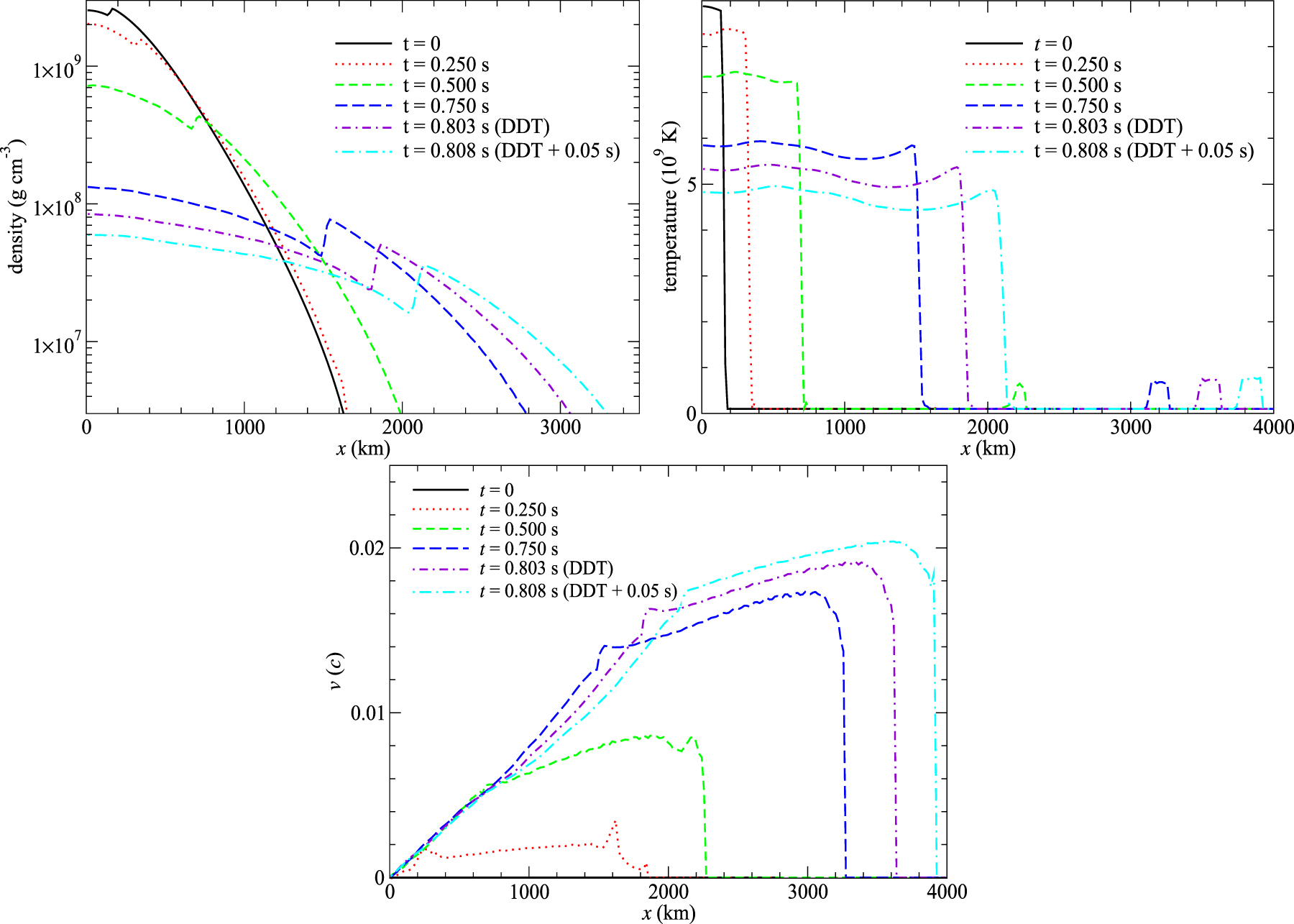
Figure 31. Similar to Figure 30, but for models Test B1 and Test B2.
Download figure:
Standard image High-resolution image
Footnotes
- 1
Notice that for a fully self-consistent manner, one should perform multidimensional simulations of evolution of the WD from the simmering phase (Woosley et al. 2004; Wunsch & Woosley 2006), such that the convective pattern and the runaway location can be captured naturally. However, this requires the use of a low Mach number solver (e.g., Zingale et al. 2011) and high resolution owing to the much slower physical process (∼hours) and the typical runaway size of the flame (∼cm; Zingale & Dursi 2007).
- 2
Outside the flame front, the matter is mildly heated up owing to numerical effects. Notice that even the flame propagation is slow compared to the speed of sound, and the injection of energy in a discrete manner still creates a sound wave that propagates outward. Thus, the nearly isobaric property of the flame cannot be exactly preserved. This mildly heats up the matter outside the flame front by compression. Notice that the details of this compressional heating depend on some model parameters, for example, the minimum temperature. In Appendix C we further discuss this aspect.
- 3
- 4
The electronic versions of these yield tables are available at http://member.ipmu.jp/shingchi.leung/research_gallery.htm#Project1 and http://supernova.astron.s.u-tokyo.ac.jp/~nomoto/yields.