


Abstract
We present a systematic analysis of the extended X-ray emission discovered around 35 FR II radio galaxies from the revised Third Cambridge Catalog (3CR) Chandra Snapshot Survey with redshifts between 0.05 and 0.9. We aimed to (i) test for the presence of extended X-ray emission around FR II radio galaxies, (ii) investigate whether the extended emission origin is due to inverse Compton (IC) scattering of seed photons arising from the cosmic microwave background (CMB) or thermal emission from an intracluster medium (ICM), and (iii) test the impact of this extended emission on hot-spot detection. We investigated the nature of the extended X-ray emission by studying its morphology and compared our results with low-frequency radio observations (i.e., ∼150 MHz) in the TGSS and LOFAR archives, as well as with optical images from Pan-STARRS. In addition, we optimized a search for X-ray counterparts of hot spots in 3CR FR II radio galaxies. We found statistically significant extended emission (>3σ confidence level) along the radio axis of ∼90% and in the perpendicular direction of ∼60% of the galaxies in our sample. We confirmed the detection of seven hot spots in the 0.5–3 keV energy range. In the cases where the emission in the direction perpendicular to the radio axis is comparable to that along the radio axis, we suggest that the underlying radiative process is thermal emission from the ICM. Otherwise, the dominant radiative process is likely nonthermal IC/CMB emission from lobes. We found that nonthermal IC/CMB is the dominant process in ∼70% of the sources in our sample, while thermal emission from the ICM dominates in ∼15% of them.
Export citation and abstract BibTeX RIS
1. Introduction
The Third Cambridge Radio Catalog (3C) is an astronomical catalog of radio sources originally detected at 159 MHz and published in 1959 by Edge et al. (1959). In 1962, Bennett created the first revised version of the catalog (3CR) using observations at 178 MHz. The 3CR catalog was considered the definitive listing of the brightest radio sources in the Northern Hemisphere at flux densities higher than 9 Jy and declinations above 5° until Laing et al. (1983) published a further revision in 1983, called 3CRR. This last revision includes galaxies that were not detected in the original catalog due to shortcomings of the original observations but otherwise meet the flux and decl. limits. The 3CRR catalog includes all extragalactic radio sources in the Northern Hemisphere with a 178 MHz flux density greater than 10.9 Jy lying at a decl. greater than 10° and Galactic latitude  . This is formally a complete sample of radio galaxies and radio-loud quasars observed at low radio frequencies and is among the most-studied catalogs of radio-loud active galactic nuclei (AGNs). An additional revision of the catalog created by Bennett (1962) was carried out by Spinrad et al. (1985), including new optical identifications of the sources in the 3CR catalog.
The 3C catalog and its revised versions have proven to be excellent surveys for understanding the properties of radio-loud sources (e.g., Schmidt 1963; Shields 1999; Tadhunter 2016), mainly due to their wide radio frequency coverage (see, e.g., Hardcastle & Worrall 2000; Giovannini et al. 2005; Madrid et al. 2006; Privon et al. 2008; Hilbert et al. 2016; Kotyla et al. 2016; Balmaverde et al. 2019). In addition, almost all 298 sources listed in the 3CR have been observed in the infrared (see, e.g., Haas et al. 2008; Baldi et al. 2010; Werner et al. 2012; Dicken et al. 2014), optical (see, e.g., Hiltner & Roeser 1991; Chiaberge et al. 2000; de Koff et al. 1996; Tremblay et al. 2009; Buttiglione et al. 2009a, 2011; Baldi et al. 2019), and UV (Allen et al. 2002; Baldi & Capetti 2008) bands in recent decades. More recently, the 3CR catalog wavelength coverage was increased up to the X-ray (see, e.g., Prieto 1996; Evans et al. 2006; Hardcastle et al. 2006; Balmaverde et al. 2012; Wilkes et al. 2013; Maselli et al. 2016; J. Kuraszkiewicz et al. 2021, in preparation).
However, despite this large suite of available multifrequency observations, before Chandra Cycle 9, only ∼60% of the 3CR sources had observations with Chandra, and only ∼30% were covered with XMM-Newton (see, e.g., Massaro et al. 2018 for a recent summary). Therefore, in 2007, we began the 3CR Chandra snapshot survey to complete the catalog X-ray coverage (Massaro et al. 2010a).
Several results have been achieved to date thanks to this snapshot survey, including several X-ray follow-up observations of interesting targets (such as 3CR 171.1 by Hardcastle et al. 2010 and Balmaverde et al. 2012, 3CR 305 by Hardcastle et al. 2012, 3CR 105 and 3CR 445 by Orienti et al. 2012, and 3CR 227 and 3CR 295 by Migliori et al. 2020). For instance, this survey led to the discovery of X-ray counterparts of radio jet knots and hot spots (see, e.g., Massaro et al. 2015 for 3CR archival observations), as well as diffuse X-ray emission around several radio sources (Massaro et al. 2009, 2018; Stuardi et al. 2018) due to the presence of a hot intracluster medium (ICM; see, e.g., 3CR 89, 3CR 196.1, and 3CR 320 by Dasadia et al. 2016, Ricci et al. 2018, and Vagshette et al. 2019, respectively, and 3CR 17 by Massaro et al. 2009 and Madrid et al. 2018, to name a few examples) or inverse Compton scattering (IC) of photons from the cosmic microwave background (CMB) in their lobes (IC/CMB; see, e.g., 3CR 459 by Maselli et al. 2018). As defined by Leahy (1993), 21 what we call "hot spots" are those surface brightness peaks at the jet termination with no significant diffuse radio emission beyond them and detected above 10 times the rms noise level at frequencies above ∼1 GHz. Hot spots are also relatively "compact" (i.e., enclosed in circular regions of ∼2''–4'' radius) and distinct from radio lobes (i.e., extended regions of diffuse radio emission on scales of tens of kiloparsecs whose perimeters are mostly well defined and with intensity tending to zero toward their perimeters). In addition, several radio galaxies with FR II morphology (i.e., edge-brightened radio sources, as defined by Fanaroff & Riley 1974) observed during the 3CR Snapshot Survey show diffuse X-ray emission with no apparent radio counterpart at gigahertz frequencies (see, e.g., Massaro et al. 2013c; Stuardi et al. 2018).
In the last two decades, examples of radio sources showing diffuse X-ray emission extending well beyond the radio structure were discovered at high redshifts (i.e.,  ; e.g., 3CR 294, HDF 130, 3CR 191, 3CR 432, 4C 60.07, 4C 03.24, and 4C 19.71 by Fabian et al. 2003, 2009; Erlund et al. 2006; and Smail et al. 2009, 2012, respectively). This X-ray emission could be due to either (i) the X-ray counterpart of extended steep-spectrum radio structures observable at megahertz but not gigahertz frequencies, (ii) the ICM whenever the source lies in a group/cluster of galaxies, or (iii) a mixture of both processes. Croston et al. (2005) studied the X-ray lobe emission of 33 FR II radio sources, finding a high rate of lobe detection (at least one per source in 20 sources of their sample) and concluding that the main X-ray emission mechanism from lobes is the IC/CMB. Following this result, Ineson et al. (2013, 2015, 2017) differentiated between thermal emission from the ICM and nonthermal emission from the IC/CMB in a sample of radio galaxies based on their radio morphology. Thus, they considered that X-ray emission spatially associated with lobes was due to the IC/CMB, while the rest of the extended X-ray emission was thermal emission from the ICM. Additionally, using a complete subset of 2 Jy sources (at
  ), Mingo et al. (2017) found lobe emission in FR II radio galaxies consistent with IC/CMB emission, confirming the previous results by Croston et al. (2005).
Carrying out the 3CR Chandra Snapshot Survey, extended X-ray emission was discovered around many of the 3CR sources (∼50 sources out of 262 observed to date; Massaro et al. 2013c). However, previous analyses were mainly focused on searching for X-ray counterparts of hot spots rather than ICM signatures. Thus, here we present a refined analysis of a selected sample of FR II radio galaxies observed in the last decade during the 3CR Chandra Snapshot Survey with the main goals of
- 1.testing for the presence of extended X-ray emission around FR II radio galaxies and comparing the structure of this emission with the radio morphology at gigahertz and ∼150 MHz frequencies (for those having available megahertz observations);
- 2.investigating the origin of this extended emission (either as IC/CMB emission from lobes or as thermal emission from the ICM); and
- 3.verifying previous claims of X-ray-detected hot spots and checking whether they could be related to fluctuations of the local X-ray background by refining the background regions and energy range used to claim their detection.
This last point arose because, although a significant number of X-ray counterparts were discovered at the locations of radio hot spots (∼40; Massaro et al. 2013c), previous analyses of 3CR Chandra Snapshot Survey observations (reported in Massaro et al. 2010a, 2012, 2013c, 2018; Stuardi et al. 2018) did not take into account the possibility that detected hot spots could be fluctuations of the extended X-ray emission due to (i) radiation arising from radio lobes and/or (ii) the presence of the ICM in those cases where the radio galaxy belongs to a galaxy cluster.
To tackle our goals, we selected a sample of radio galaxies with clear FR II radio morphology, observed as part of the 3CR Chandra Snapshot Survey, to create a uniformly observed sample of radio sources (see Section 2 for all details of the sample selection criteria).
We additionally computed surface brightness profiles of FR II radio galaxies with clearly detected extended X-ray emission along their radio axes and verified the presence of galaxy clusters by using archival optical observations to test for the presence of red sequences (i.e., a color–magnitude relation for galaxies belonging to the same galaxy cluster; see Visvanathan & Sandage 1977) in the fields of those galaxies with diffuse X-ray emission not spatially associated with the radio structure. Finally, we performed a comparison with low radio frequencies (i.e., ∼150 MHz) available in the Tata Institute of Fundamental Research (TIFR) Giant Metrewave Radio Telescope (GMRT) Sky Survey (TGSS 22 ) and the LOw-Frequency ARray (LOFAR 23 ) Two-meter Sky Survey (LoTSS) archives.
The paper is organized as follows. In Section 2, we present the sample selection. The Chandra data reduction is described in Section 3, while Section 4 is dedicated to the data analysis. Results are described in Section 5, and a comparison with observations carried out at radio, infrared, and optical frequencies is shown in Section 6. Section 7 is devoted to our discussion and conclusions. Tables with properties for each image of all selected radio sources, as well as images for all sources, are collected in Appendix A. Finally, results from the serendipitous discovery of hot spots made with the Wide-field Infrared Survey Explorer (WISE 24 ) are shown in Appendix B.
Unless otherwise stated, we adopt cgs units for numerical results, and we also assume a flat cosmology with H0 = 69.6 km s−1 Mpc−1,  , and
, and  (Bennett et al. 2014). Spectral indices, α, are defined by flux density,
  . Optical magnitudes obtained from the Panoramic Survey Telescope and Rapid Response System (Pan-STARRS
25
; Chambers et al. 2016) catalog are in a photometric system close to the AB magnitudes described in Tonry et al. (2012), with uncertainties between ∼10−1 and 10−3 mag. The average background level of the X-ray images is ∼0.04 photons arcsec−1 in the energy band of 0.5–3 keV.
. Optical magnitudes obtained from the Panoramic Survey Telescope and Rapid Response System (Pan-STARRS
25
; Chambers et al. 2016) catalog are in a photometric system close to the AB magnitudes described in Tonry et al. (2012), with uncertainties between ∼10−1 and 10−3 mag. The average background level of the X-ray images is ∼0.04 photons arcsec−1 in the energy band of 0.5–3 keV.
2. Sample Selection
We initially selected all radio galaxies with a classical FR II radio morphology (i.e., edge-brightened; Fanaroff & Riley 1974) out of those listed in the 3CR catalog and observed during the 3CR Chandra Snapshot Survey before Cycle 20. Radio sources belonging to the 3CRR sample were not included because a dedicated paper is already in preparation (B. J. Wilkes et al. 2021, in preparation). The criteria to select FR II radio sources on the basis of their radio morphology are as adopted in Capetti et al. (2017). Additionally, we expect the physical mechanisms that give rise to potential X-ray emission in FR IIs to be different from those of FR Is (i.e., edge-darkened) because of differences in their particle content (see Croston et al. 2018).
Our initial sample includes 72 sources. Then, we excluded (i) sources with an angular size (measured as the angular separation of the radio position of both hot spots) smaller than 5'' measured at gigahertz frequencies in radio maps obtained from the Very Large Array (VLA 26 ; Condon et al. 1998) and (ii) three sources, namely, 3CR 187, 3CR 196.1, and 3CR 320, for which deeper investigations are in preparation or have already been published (see A. Paggi et al. 2021, in preparation; Ricci et al. 2018; Vagshette et al. 2019, respectively). We chose to exclude sources with angular sizes below 5'' because, at the redshift range of our sample, 5'' corresponds to 5–15 kpc; therefore, we exclude compact radio sources. In addition, ∼90% of the Chandra point-spread function (PSF) is enclosed in a circular region of 2'' radius. Thus, selecting sources that extend beyond 5'' allows us to detect extended X-ray emission beyond the relatively bright unresolved core present in a large fraction of FR II radio galaxies (see, e.g., Massaro et al. 2011b).
Our final sample thus includes 35 FR II radio galaxies, 24 optically classified as high-excitation radio galaxies (HERGs), seven classified as low-excitation radio galaxies (LERGs), two classified as broad-line radio galaxies (BLRGs; see, e.g., Laing et al. 1994; Buttiglione et al. 2009b; Baldi et al. 2019, for works on optical classification of radio galaxies), and two with no clear optical identification (3CR 103 and 3CR 435B). In total, these FR II radio galaxies have 71 hot spots, since 3CR 133 shows a double hot spot.
Table 1 gathers information about all of the galaxies in our sample, including their coordinates, redshift, kiloparsec scale, angular size according to the radio morphology, and optical classification, as well as information about the X-ray and radio observations used in the analysis.
Table 1. Source Parameters for the Selected Sample of FR II Radio Galaxies
| 3CR | R.A. | Decl. | z | Kiloparsec Scale | Ang. Size | Opt. | Chandra | Radio Freq. | Beam Size |
|---|---|---|---|---|---|---|---|---|---|
| Name | (J2000) | (J2000) | (kpc arcsec–1) | (arcseconds) | Class | ObsID | (GHz) | (arcseconds) | |
| (1) | (2) | (3) | (4) | (5) | (6) | (7) | (8) | (9) | (10) |
| 18 | 00 40 50.53 | +10 03 26.65 | 0.188 | 3.167 | 55 | BLRG | 9293 | 1.4 | 1.70 |
| 44* | 01 31 21.65 | +06 23 43.14 | 0.66 | 7.059 | 64 | HERG | 16048 | ⋯ | ⋯ |
| 52 | 01 48 28.91 | +53 32 28.04 | 0.29 | 4.389 | 55 | HERG | 9296 | 8.0 | 0.38 |
| 54 | 01 55 30.26 | +43 45 59.05 | 0.827 | 7.694 | 53 | HERG | 16049 | 8.0 | 0.40 |
| 63 | 02 20 54.30 | -01 56 50.65 | 0.175 | 2.990 | 18 | HERG | 12722 | 8.0 | 3.36 |
| 69 | 02 38 02.66 | +59 11 50.50 | 0.458 | 5.878 | 47 | HERG | 18092 | 4.8 | 5.00 |
| 103 | 04 08 03.22 | +43 00 33.93 | 0.33 | 4.796 | 82 | 13874 | 1.4 | 3.27 | |
| 107 | 04 12 22.62 | -00 59 32.69 | 0.785 | 7.556 | 15 | HERG | 16052 | 4.8 | 0.46 |
| 114 | 04 20 22.23 | +17 53 56.86 | 0.815 | 7.655 | 53 | LERG | 16053 | 4.8 | 1.47 |
| 133 | 05 02 58.47 | +25 16 25.27 | 0.2775 | 4.254 | 12 | HERG | 9300 | 1.4 | 0.98 |
| 135 | 05 14 08.36 | +00 56 32.48 | 0.1273 | 2.294 | 121 | HERG | 9301 | 8.0 | 0.66 |
| 165* | 06 43 07.40 | +23 19 02.60 | 0.2957 | 4.449 | 76 | LERG | 9303 | ⋯ | ⋯ |
| 166 | 06 45 24.10 | +21 21 51.27 | 0.2449 | 3.883 | 39 | LERG | 12727 | 1.4 | 1.37 |
| 169.1 | 06 51 14.83 | +45 09 28.48 | 0.633 | 6.931 | 46 | HERG | 16056 | 8.0 | 0.40 |
| 180 | 07 27 04.88 | -02 04 30.34 | 0.22 | 3.581 | 107 | HERG | 12728 | 8.0 | 0.36 |
| 197.1 | 08 21 33.60 | +47 02 37.15 | 0.1282 | 2.307 | 15 | HERG | 9306 | 4.8 | 1.32 |
| 198* | 08 22 33.58 | +05 56 30.82 | 0.0814 | 1.545 | 283 | HERG | 12730 | ⋯ | ⋯ |
| 223.1 | 09 41 24.02 | +39 44 41.71 | 0.1075 | 1.979 | 78 | HERG | 9308 | 1.4 | 1.67 |
| 268.2 | 12 00 58.73 | +31 33 21.55 | 0.362 | 5.096 | 97 | HERG | 13876 | 4.8 | 0.46 |
| 272* | 12 24 28.44 | +42 06 36.51 | 0.944 | 8.005 | 56 | HERG | 16061 | ⋯ | ⋯ |
| 287.1 | 13 32 53.27 | +02 00 45.86 | 0.2156 | 3.526 | 112 | HERG | 9309 | 1.4 | 5.00 |
| 293.1 | 13 54 40.52 | +16 14 43.15 | 0.709 | 7.272 | 44 | HERG | 16066 | 4.8 | 0.42 |
| 306.1 | 14 55 01.41 | -04 20 59.94 | 0.441 | 5.751 | 90 | HERG | 13885 | 4.8 | 1.75 |
| 313 | 15 11 00.04 | +07 51 50.15 | 0.461 | 5.900 | 133 | HERG | 13886 | 8.0 | 2.43 |
| 332 | 16 17 42.54 | +32 22 34.39 | 0.151 | 2.649 | 69 | HERG | 9315 | 1.4 | 4.40 |
| 357 | 17 28 20.11 | +31 46 02.55 | 0.166 | 2.866 | 76 | LERG | 12738 | 4.8 | 1.92 |
| 379.1 | 18 24 33.00 | +74 20 58.87 | 0.256 | 4.013 | 76 | HERG | 12739 | 1.4 | 1.49 |
| 403.1* | 19 52 30.44 | -01 17 22.35 | 0.0554 | 1.083 | 107 | LERG | 12741 | ⋯ | ⋯ |
| 411 | 20 22 08.43 | +10 01 11.38 | 0.467 | 5.943 | 26 | HERG | 13889 | 1.4 | 1.30 |
| 430 | 21 18 19.10 | +60 48 07.68 | 0.0555 | 1.086 | 85 | LERG | 12744 | 4.8 | 1.34 |
| 434* | 21 23 16.24 | +15 48 05.80 | 0.322 | 4.718 | 13 | LERG | 13878 | ⋯ | ⋯ |
| 435A* | 21 29 05.45 | +07 32 59.75 | 0.471 | 5.971 | 24 | BLRG | 13890 | ⋯ | ⋯ |
| 435B | 21 29 06.10 | +07 32 54.80 | 0.865 | 7.804 | 44 | 13890 | 4.8 | 1.76 | |
| 456* | 23 12 28.08 | +09 19 26.39 | 0.233 | 3.741 | 7 | HERG | 12746 | ⋯ | ⋯ |
| 458 | 23 12 52.08 | +05 16 49.80 | 0.289 | 4.378 | 197 | HERG | 12747 | 4.8 | 2.33 |
Note. Column descriptions: (1) source name; (2) R.A.; (3) decl.; (4) redshift; (5) kiloparsec scale; (6) estimation of the radio emission angular size, measured as the angular separation between the radio positions of the hot spots; (7) optical classification; (8) Chandra observation identification number; (9) frequency of radio maps (all obtained from the VLA archive) used for the registration (see Section 3); (10) major axis beam size of the radio maps. Sources marked with an asterisk are those that could not be registered.
Download table as: ASCIITypeset image
3. Chandra Data Reduction
Data reduction for all selected observations was carried out following the same procedures described in the Chandra Interactive Analysis of Observations (CIAO; Fruscione et al. 2006) threads 27 and using CIAO v4.11 and Chandra Calibration Database v4.8.2. Here we report basic details and differences specifically adopted to achieve our goals with respect to our previous analyses (see, e.g., Massaro et al. 2010a and Massaro et al. 2011b for additional information).
We binned images in the 0.5–3 keV energy range for all radio galaxies in our sample. We chose to restrict our analysis to the 0.5–3 keV energy range because extended X-ray radiation is emitted predominantly in the soft band. This could only affect our calculations for a source in a very dense environment. However, we do not expect that to be the case for sources in our sample because all sources were already inspected in the original data papers (see Ineson et al. 2013, 2015, 2017; Croston et al. 2017).
Astrometric registration between radio and X-ray images was performed by adopting the same procedure used by previous papers on the 3CR Chandra Snapshot Survey (see Massaro et al. 2010a, 2012, 2013c, 2018; Stuardi et al. 2018) and deviating from those results by <1''. The frequencies and beam sizes of the radio maps, obtained from the VLA archive, used in each case are reported in Table 1, where sources with no radio frequency, indicated in the table, are those for which no astrometric registration was possible (due to the lack of core detection in radio observations), namely, 3CR 44, 3CR 165, 3CR 198, 3CR 272, 3CR 403.1, 3CR 434, 3CR 435A, and 3CR 456.
In Figures 10–15, we show Chandra 0.5–3 keV images for all sources in our sample with different pixel sizes and smoothed with different Gaussian kernels, as reported in Table 4. Overlaid contours correspond to the radio emission at different frequencies, as reported in Table 4. Radio maps were obtained from the VLA archive. We removed pointlike sources from these images (including the X-ray nuclei of the radio galaxies but not their hot spots) to highlight the presence of X-ray extended emission, although we only used the point-source-subtracted images for visualization purposes (see Figures 10–15) and to create X-ray surface brightness profiles (see Section 4). The procedure adopted is reported in the following. We detected pointlike sources in the range 0.5–7 keV using the wavdetect task, available in CIAO, with a sequence of  wavelet scales from 1 to 16 to cover different-sized sources and a false-positive probability threshold set to the value of 10−6, which is the value recommended for a 1024 × 1024 image in the CIAO threads
28
to make sure we do not oversubtract point sources. Next, we generated corresponding elliptical regions using the roi task, and with the dmfilth task, we built the final pointlike source-subtracted images. The dmfilth task replaces counts in each region where a pointlike source is detected, defined by roi, by sampling the Poisson distribution of the pixel values in concentric background regions. As an example, in Figure 1, we show the field of 3CR 313, marking the pointlike sources detected by wavdetect.
wavelet scales from 1 to 16 to cover different-sized sources and a false-positive probability threshold set to the value of 10−6, which is the value recommended for a 1024 × 1024 image in the CIAO threads
28
to make sure we do not oversubtract point sources. Next, we generated corresponding elliptical regions using the roi task, and with the dmfilth task, we built the final pointlike source-subtracted images. The dmfilth task replaces counts in each region where a pointlike source is detected, defined by roi, by sampling the Poisson distribution of the pixel values in concentric background regions. As an example, in Figure 1, we show the field of 3CR 313, marking the pointlike sources detected by wavdetect.

Figure 1. The 0.5–3 keV Chandra image of 3CR 313. Pointlike sources detected in the 3CR 313 field using wavdetect are marked with black arrows. The image has been smoothed using a Gaussian kernel of 492. The position of the nucleus is marked with a cross. The marked point sources are removed during the point-source subtraction to obtain the images in Figure 13. This image shows how effective wavdetect is at detecting point sources with the parameters we selected.
Download figure:
Standard image High-resolution imageSince some of the background and foreground X-ray sources could be active galaxies (see, e.g., Horst et al. 2008; Eckart et al. 2010; Massaro et al. 2011a; Assef et al. 2013), we tested whether the X-ray sources detected with wavdetect have a mid-infrared counterpart in the recent release of the WISE catalog (i.e., AllWISE 29 ). Within a circle of radius 30'' centered on the sources, in our sample, all point sources from the AllWISE catalog with X-ray counterparts were detected by wavdetect. Therefore, this suggests that the thresholds chosen to run wavdetect are reliable.
4. Chandra Data Analysis
4.1. Detection of Hot Spots and Extended X-Ray Emission
Throughout this analysis, we used unbinned and unsmoothed images with photons restricted to the 0.5–3 keV band. To search for extended X-ray emission surrounding radio galaxies in our sample, as well as the X-ray counterparts of radio hot spots, we considered three different regions (as shown in Figure 2):
- 1.the hot-spot regions, circular regions of 2'' radius centered on the radio position of all hot spots and radio cores;
- 2.a rectangular region, defined along the radio axis on the basis of radio contours, excluding the regions corresponding to both the radio core and the hot spots; and
- 3.a circular region, centered on the radio core position and extended as the previous one but excluding the rectangular region along the radio axis, radio core, and hot spots (circles of 2'' radius each).

Figure 2. Left panel: example of regions chosen for the detection of hot spots, as well as extended X-ray emission along and perpendicular to the radio axis. The 0.5–3 keV X-ray emission was smoothed with a 1181 Gaussian kernel and pixels of 0984. The 8 GHz radio emission is shown as blue contours whose levels are reported in Table 4. Similar regions to the ones shown were chosen for the other sources. Right panel: example of regions chosen as background for 3CR 313 (in black) in the 0.5–3 keV band Chandra observation. The X-ray emission and radio contours are the same as those in the left panel. These background regions (and similar ones for the other sources) were used while carrying out our extended emission and hot-spot detection analysis.
Download figure:
Standard image High-resolution imageThe starting level of radio contours to select these regions was set to five times the rms of the radio map, as reported in Table 4, which is usually ∼1 mJy beam−1.
The X-ray detection significance for the hot spots was estimated using the following procedure.
- 1.We computed the background, choosing an appropriate region as described below.
- 2.We identified a region for the X-ray hot spot (a 2'' radius circular region centered at the location of the radio hot spot).
- 3.We computed the number of photons in the hot-spot region.
- 4.Then, assuming the number of photons in the background follows a Poissonian distribution with the number of photons that we measured for the background region as the mean, we compute the probability of detecting the observed number of photons in the hot-spot region. The detection probability is indicated using the Gaussian equivalent σ.
For each hot-spot region selected, we assume two different background regions: (i) the standard X-ray background measured in a circular region as large as the region perpendicular to the radio axis and located on the same charge-coupled device (CCD) chip, far enough from the radio galaxy (i.e., at least a few tens of arcseconds) to avoid the smearing of the PSF on CCD borders and contamination from the source, rescaled to the hot-spot region size; and (ii) a so-called local background, defined as the region along the radio axis where the IC/CMB could be present, also rescaled to the size of the hot-spot region. In Table 2, we show the detection significance obtained for all features, and in Table 3, we show the background-subtracted number of photons in each region using the standard background.
Table 2. Detection Significance for Different Radio Components
| 3CR Name |

|

| id1 |

|

| id2 |

|

|
|---|---|---|---|---|---|---|---|---|
| (1) | (2) | (3) | (4) | (5) | (6) | (7) | (8) | (9) |
| 18 | >5 | >5 | n29 | 4 | ⋯ | s26 | ⋯ | ⋯ |
| 44 | >5 | 4 | n45 c | 3 | ⋯ | s19 | 3 | ⋯ |
| 52 | >5 | 5 | n29 b , c | ⋯ | ⋯ | s26 | ⋯ | ⋯ |
| 54 | 4 | ⋯ | n34 | ⋯ | ⋯ | s19 b | 4 | 3 |
| 63 | >5 | >5 | n11 | ⋯ | ⋯ | s7 | >5 | ⋯ |
| 69 | 5 | ⋯ | n22 d | ⋯ | ⋯ | s25 | 3 | ⋯ |
| 103 | >5 | ⋯ | n45 | ⋯ | ⋯ | s37 | ⋯ | ⋯ |
| 107 a | >5 | ⋯ | n8 | ⋯ | ⋯ | s7 | ⋯ | ⋯ |
| 114 | 5 | 3 | n29 | ⋯ | ⋯ | s24 | ⋯ | ⋯ |
| 133 | >5 | >5 | w4 | ⋯ | ⋯ | e5 c | >5 | ⋯ |
| 135 | ⋯ | ⋯ | e77 | ⋯ | ⋯ | w43 | ⋯ | ⋯ |
| 165 | >5 | >5 | n29 | ⋯ | ⋯ | s48 | ⋯ | ⋯ |
| 166 | >5 | 5 | n15 | 4 | ⋯ | s24 d | ⋯ | ⋯ |
| 169.1 | 3 | ⋯ | n25 | ⋯ | ⋯ | s22 | 3 | ⋯ |
| 180 | 3 | ⋯ | n43 | ⋯ | ⋯ | s63 | ⋯ | ⋯ |
| 197.1 | >5 | >5 | n6 | 3 | ⋯ | s10 | 3 | ⋯ |
| 198 | >5 | 4 | n107 | ⋯ | ⋯ | s176 | ⋯ | ⋯ |
| 223.1 | 3 | ⋯ | n40 | ⋯ | ⋯ | s38 | ⋯ | ⋯ |
| 268.2 | 5 | ⋯ | n42 | ⋯ | ⋯ | s55 b | 3 | 3 |
| 272 | 4 | ⋯ | n24 | 3 | ⋯ | s32 | 3 | ⋯ |
| 287.1 | >5 | 5 | w65 c | 4 | ⋯ | e47 | 3 | ⋯ |
| 293.1 | 5 | 4 | n15 | ⋯ | ⋯ | s29 | ⋯ | ⋯ |
| 306.1 | >5 | ⋯ | n44 | 3 | ⋯ | s47 c | ⋯ | ⋯ |
| 313 | >5 | 4 | n90 b | 4 | 3 | s43 b | 4 | 3 |
| 332 | >5 | 5 | n34 d | 3 | ⋯ | s34 | ⋯ | ⋯ |
| 357 | >5 | ⋯ | w32 | ⋯ | ⋯ | e44 | ⋯ | ⋯ |
| 379.1 | ⋯ | 3 | n44 | ⋯ | ⋯ | s32 | ⋯ | ⋯ |
| 403.1 | 3 | >5 | e35 | ⋯ | ⋯ | w72 | ⋯ | ⋯ |
| 411 | >5 | >5 | w13 | 3 | ⋯ | e13 | ⋯ | ⋯ |
| 430 | ⋯ | >5 | n44 | ⋯ | ⋯ | s41 | ⋯ | ⋯ |
| 434 | 3 | ⋯ | w8 | ⋯ | ⋯ | e5 | 4 | 3 |
| 435A | >5 | 4 | n9 | 3 | ⋯ | s14 | 4 | ⋯ |
| 435B | >5 | >5 | e22 | 3 | ⋯ | w22 | 4 | ⋯ |
| 456 | 4 | >5 | n4 | >5 | 4 | s3 | 4 | ⋯ |
| 458 | 5 | ⋯ | e75 b | 4 | 4 | w122 | ⋯ | ⋯ |
Notes. Column descriptions: (1) source name, (2) detection significance of the emission along the radio axis, (3) detection significance of the emission perpendicular to the radio axis, (4) first hot-spot label, (5) detection significance of the first hot spot using the standard X-ray background, (6) detection significance of the first hot spot using the local background, (7) second hot-spot label, (8) detection significance of the second hot spot using the standard X-ray background, (9) detection significance of the second hot spot using the local background.
a Sources with extended X-ray emission previously reported in the survey papers. b Hot spots detected in previous survey papers. c Hot spots detected in the Chandra Source Catalog. d Hot spots detected in WISE; 3CR 133 presents a double hot spot, e6, detected only over the standard background at a 5σ level of confidence.Download table as: ASCIITypeset image
As an example, in the left panel of Figure 2, the regions selected to carry out our analysis for 3CR 313 are shown over its 0.5–3 keV X-ray emission. On the other hand, in the right panel of Figure 2, we show the standard X-ray background compared to the local background, also for 3CR 313.
We chose to label the region along the radio axis as local background only when this region was used as background. We used the number of photons in the standard X-ray background to also compute the detection significance of the extended X-ray emission along and perpendicular to the radio axis.
4.2. X-Ray Surface Brightness Profiles
We computed 0.5–3 keV exposure-corrected X-ray surface brightness profiles in two directions: (i) along and (ii) perpendicular to the radio axis. To estimate the background, we used blank-sky files available in the Chandra Calibration Database. Final background event files were obtained by reprojecting blank-sky files to the same tangent planes as observations. Next, we renormalized the exposure times of the background event files, making the observation count rates in the 9–12 keV band match the background file count rates in the same band, where we expect emission to come mainly from the particle background (the same procedure as adopted and described in Hickox & Markevitch 2006).
We built these profiles for the four sources in our sample with more than 100 photons along the radio axis, namely, 3CR 18, 3CR 198, 3CR 287.1, and 3CR 332. Figure 3 shows an example for the bins chosen for 3CR 18. We chose regions along the radio axis on the basis of the radio emission (as shown in Figure 3). Once these regions were chosen, we built radial bins with fixed widths of 4''–8'', depending on each source, up to the maximum extent of the radio contours. Beyond the radio structure, we extended the radial profiles until a signal-to-noise ratio (S/N) of 3 was achieved or a maximum radius (set to be inside the CCD chip) was reached.

Figure 3. Directions along and perpendicular to the radio axis chosen for 3CR 18, as well as bins along the radio axis. The image shows the X-ray emission between 0.5 and 3 keV with 1.4 GHz VLA contours overlaid in blue. The parameters of the X-ray image and radio contour levels are given in Table 4. These directions and bins were chosen based on the radio morphology and used to make surface brightness profiles.
Download figure:
Standard image High-resolution image5. Results
5.1. Detecting X-Ray Extended Emission
In comparison with the previous analyses carried out in the data papers of the 3CR Chandra Snapshot Survey, we restricted our analysis to the energy range 0.5–3 keV because the extended X-ray emission, coming from both the thermal ICM and the IC/CMB, peaks in the soft band. We also chose to use the soft band to detect X-ray counterparts of hot spots, since these observations were taken during Chandra Cycles 9, 12, and 13, when the sensitivity of the soft band was not significantly degraded. Additionally, the hard band generally presents a higher background than the soft band. This is supported by the fact that during the XJET project (see Harris et al. 2010; Massaro et al. 2010b, 2010c, and Massaro et al. 2011b), only two hot spots out of the 32 detected in radio galaxies and quasars presented more counts in the hard band than in the soft band. In this work, the detection analysis was carried out using the full band (0.5–7 keV), observations had exposure times of less than 35 ks, and the soft band was defined as 0.5–2 keV. However, we also checked the influence of carrying out this analysis using the full band.
Table 2 shows the results of the detection analysis for regions along the radio axis and perpendicular to the radio axis and hot spots, where  and
and  are the detection significance of the emission along and perpendicular to the radio axis and
  and
and  are the detection significance of hot spots against the standard and local background, respectively. Sources and hot spots labeled with asterisks are those previously detected in the survey papers.
We detected extended X-ray emission (in the 0.5–3 keV range) along the radio axis against the standard background for 32 out of 35 radio galaxies (i.e., ∼90%) in our sample above a 3σ level of confidence, while this number decreases to 24 (i.e., ∼70%) when considering a threshold of 5σ.
On the other hand, we detected extended X-ray emission in the direction perpendicular to the radio axis using the standard background in 22 radio galaxies out of 35 above the 3σ confidence level (∼60%) and 15 (∼40%) when setting the level of confidence above 5σ.
5.2. Detecting X-Ray Counterparts of Hot Spots
Using the background estimated in the standard region, we detected 30 hot spots out of 35 sources in our sample, all above the 3σ confidence level, with four of them above 5σ. If, instead, we consider the background in the local region to guarantee that detected hot spots are not just due to background fluctuations of any diffuse emission, the number of detected hot spots decreases to seven above the 3σ confidence level (∼10% of the total number of hot spots). Therefore, ∼75% of hot spots detected, without taking into account the local background, could be fluctuations of the extended X-ray emission along the radio axis. Using the full band (0.5–7 keV) in our detection analysis, we detected (>3σ) only three hot spots out of those not detected using the soft band, namely, s7 in 3CR 107, s63 in 3CR 180, and s47 in 3CR 306.1, while the significance level of ∼80% (i.e., 56) of the hot spots in our sample decreases when we consider the full band instead of the soft band, with the significance of nine decreasing below 3σ.
The results of the detection analysis are shown in Table 2. We labeled hot spots using the same notation as in the XJET project 30 (Massaro et al. 2011b): their orientation (north, n, south, s, east, e, or west, w) followed by their angular separation (in arcseconds) from the core of the radio galaxy.
In Table 3, we show a summary of the sources with newly detected hot spots compared with previous works on the 3CR Chandra Snapshot Survey. Previous works detected only six hot spots (∼10%) for the same sources/observations analyzed here, while only five of them are detected in the second version of the Chandra Source Catalog (CSC2 31 ; see Evans et al. 2010 for the first version of the catalog and Evans et al. 2019, 2020 for the second release). However, the detection of these hot spots in the CSC2 is only marginal (below a 3σ confidence level), and, therefore, they could be spurious detections instead of X-ray counterparts of the radio hot spots. Using the standard background and restricting the energy to the soft band (in contrast with previous analyses, including that of CSC2, that used the full band), we detected new hot spots in 16 sources (see Table 3); while using the local background, we detected new hot spots in two sources and confirmed hot spots from previous analyses in four sources (see Table 3), discarding only one hot spot whose detection was claimed in previous survey papers (i.e., n29 in 3CR 52).
Table 3. Radio and X-Ray Parameters Used for the Appendix Images of Figures 10–15
| 3CR | Optical | Hot Spot | Hot Spot | Along | Perpendicular to | ρ | New Hot Spots | Optical | Dominant |
|---|---|---|---|---|---|---|---|---|---|
| Name | Classification | 1 | 2 | Radio Axis | Radio Axis | Standard, Local | Cluster | Process | |
| (1) | (2) | (3) | (4) | (5) | (6) | (7) | (8) | (9) | (10) |
| 18 | BLRG | 2.98 (1.90) | 0.00 (0.14) | 130.70 (13.69) | 44.80 (9.89) | 4.4 | Y,— | IC/CMB | |
| 44 | HERG | 1.98 (1.56) | 0.98 (1.14) | 25.10 (8.00) | 17.20 (8.82) | 2.1 | Y,— | ✓ | IC/CMB |
| 52 | HERG | 0.00 (0.14) | 0.98 (1.14) | 21.00 (7.65) | 20.40 (8.82) | 1.6 | ⋯ | ✓ | ICM |
| 54 | HERG | 0.00 (0.14) | 2.98 (1.90) | 9.90 (5.37) | 4.40 (5.53) | 2.4 | N, N | IC/CMB | |
| 63 | HERG | 0.00 (0.14) | 4.98 (2.40) | 16.60 (4.76) | 9.20 (4.06) | 3.9 | Y,— | ⋯ | |
| 69 | HERG | 0.00 (0.14) | 0.98 (1.14) | 15.80 (6.86) | 4.4 (5.89) | 2.4 | Y,— | IC/CMB | |
| 103 | 0.00 (0.14) | 0.98 (1.14) | 20.30 (8.07) | 3.5 (9.43) | 3.1 | ⋯ | IC/CMB | ||
| 107 | HERG | 0.00 (0.14) | 0.98 (1.14) | 6.70 (3.19) | 1.40 (2.19) | 7.4 | ⋯ | IC/CMB | |
| 114 | LERG | 0.00 (0.14) | 0.00 (0.14) | 12.10 (5.58) | 10.10 (9.14) | 2.8 | ⋯ | IC/CMB | |
| 133 | HERG | 0.00 (0.14) | 2.98 (1.90) | 11.90 (3.78) | 6.70 (3.19) | 4.1 | N,— | IC/CMB | |
| 135 | HERG | 0.00 (0.14) | 0.98 (1.14) | 4.80 (8.61) | 7.00 (15.42) | 1.2 | ⋯ | ✓ | ⋯ |
| 165 | LERG | 0.00 (0.14) | 0.98 (1.14) | 39.20 (10.36) | 54.20 (16.52) | 2.1 | ⋯ | ICM | |
| 166 | LERG | 1.98 (1.56) | 0.00 (0.14) | 28.20 (7.24) | 13.10 (6.10) | 2.5 | Y,— | IC/CMB | |
| 169.1 | HERG | 0.00 (0.14) | 0.98 (1.14) | 6.30 (4.64) | 6.50 (6.48) | 1.8 | Y,— | IC/CMB | |
| 180 | HERG | 0.00 (0.14) | 0.00 (0.14) | 6.50 (6.16) | 16.00 (15.20) | 1.5 | ⋯ | IC/CMB | |
| 197.1 | HERG | 0.98 (1.14) | 0.98 (1.14) | 29.60 (5.10) | 16.60 (5.79) | 7.1 | Y,— | ✓ | IC/CMB |
| 198 | HERG | 0.00 (0.14) | 0.00 (0.14) | 129.60 (33.31) | 124.90 (64.45) | 1.4 | ⋯ | ✓ | IC/CMB |
| 223.1 | HERG | 0.00 (0.14) | 0.00 (0.14) | 9.80 (8.90) | 12.50 (16.69) | 1.4 | ⋯ | IC/CMB | |
| 268.2 | HERG | 0.98 (1.14) | 1.98 (1.56) | 25.10 (11.70) | 1.40 (12.05) | 2.0 | N, N | IC/CMB | |
| 272 | HERG | 0.98 (1.14) | 0.98 (1.14) | 10.50 (6.98) | 9.30 (11.87) | 1.8 | Y,— | IC/CMB | |
| 287.1 | HERG | 0.00 (0.14) | 0.98 (1.14) | 167.20 (16.99) | 27.20 (12.85) | 7.2 | Y,— | IC/CMB | |
| 293.1 | HERG | 0.00 (0.14) | 0.00 (0.14) | 14.40 (6.50) | 17.00 (8.85) | 1.7 | ⋯ | IC/CMB | |
| 306.1 | HERG | 1.98 (1.56) | 0.98 (1.14) | 24.10 (9.22) | 9.10 (11.71) | 2.5 | Y,— | ✓ | IC/CMB |
| 313 | HERG | 2.98 (1.90) | 2.98 (1.90) | 93.60 (16.65) | 41.8 (20.10) | 2.7 | N, N | ✓ | IC/CMB |
| 332 | HERG | 1.98 (1.56) | 0.00 (0.14) | 203.80 (19.17) | 47.60 (18.83) | 7.1 | Y,— | ✓ | IC/CMB |
| 357 | LERG | 0.00 (0.14) | 0.00 (0.14) | 31.80 (12.40) | 15.10 (15.39) | 1.8 | ⋯ | ✓ | IC/CMB |
| 379.1 | HERG | 0.00 (0.14) | 0.00 (0.14) | 2.50 (5.90) | 12.60 (9.22) | 0.7 | ⋯ | ICM | |
| 403.1 | LERG | 0.00 (0.14) | 0.00 (0.14) | 15.40 (9.94) | 62.90 (21.67) | 1.1 | ⋯ | ✓ | ICM |
| 411 | HERG | 1.98 (1.56) | 0.98 (1.14) | 68.80 (9.46) | 55.30 (10.95) | 1.2 | Y,— | ICM | |
| 430 | LERG | 0.00 (0.14) | 0.00 (0.14) | 7.80 (7.44) | 50.20 (16.19) | 0.8 | ⋯ | ICM | |
| 434 | LERG | 0.00 (0.14) | 2.98 (1.90) | 4.20 (3.13) | 3.30 (5.54) | 2.0 | Y, Y | ✓ | ⋯ |
| 435A | BLRG | 0.98 (1.14) | 1.98 (1.56) | 6.70 (3.19) | 6.60 (4.01) | 3.7 | Y,— | IC/CMB | |
| 435B | 0.98 (1.14) | 1.98 (1.56) | 17.70 (5.99) | 18.60 (7.82) | 2.4 | Y,— | IC/CMB | ||
| 456 | HERG | 9.98 (3.30) | 2.98 (1.90) | 2.90 (2.05) | 14.30 (5.30) | 2.2 | Y, Y | ⋯ | |
| 458 | HERG | 2.98 (1.90) | 0.00 (0.14) | 39.40 (15.58) | 20.90 (20.03) | 1.6 | N, N | ✓ | IC/CMB |
Note. Column 1: source name. Column 2: optical classification. Columns 3–6: net source photons measured in the hot spots, along and perpendicular to the radio axis, with the corresponding background photons for those regions in parentheses. Background here refers to the standard background. Column 7: ratio of photons along and perpendicular to the radio axis as defined by Equation (1). Column 8: flag for sources with new hot spots detected using the standard and local background. "Y" indicates a newly detected hot spot, "N" indicates a hot spot detected in this work that was previously detected by other works, and "—" indicates a nondetection. Column 9: flag that indicates whether the presence of an optical galaxy cluster was previously reported. Column 10: dominant emission process for the extended X-ray emission.
Download table as: ASCIITypeset image
Photons in both hot-spot regions, as well as along the radio axis and in the region perpendicular to the radio axis (see Section 4 for the definition of each region) and their corresponding background levels, are reported in Table 3, together with an estimate of the ratio of photons along and perpendicular to the radio axis (ρ), defined as

where  and
and  are the number of background-subtracted photons along the radio axis and in the region perpendicular to the radio axis, respectively, and A∥ and A⊥ are the areas of the regions along and perpendicular to the radio axis. This parameter gives us an estimate of the importance of the extended X-ray emission perpendicular to the radio axis with respect to the emission along the radio axis. In this table, we also compiled information about which sources present newly detected hot spots, which ones are in known optical galaxy clusters, and the dominant emission process responsible for the extended X-ray emission in each case, according to the detection significance of the extended emission along and perpendicular to the radio axis.
5.3. Source Details
For a few targets, we found that the extended X-ray emission discovered here presents intriguing structures, namely, 3CR 103, 3CR 268.2, 3CR 403.1, 3CR 430, and 3CR 458, with no associated Planck galaxy clusters (see Ade et al. 2016; Piffaretti et al. 2011). These structures are discussed below.
3CR 103 (z = 0.33). We did not detect significant emission perpendicular to the radio axis arising from this galaxy, but we detected extended emission at 93'' (446 kpc at the source redshift) above the 5σ confidence level to the southwest of the galaxy that could indicate the presence of a galaxy cluster. However, there is a bright star close to the position of the extended emission that prevented us from obtaining the precise redshift estimates of nearby optical sources necessary to verify the presence of a galaxy cluster/group and deserving future follow-up observations.
The left panel of Figure 4 shows an optical image from Pan-STARRS of the field of 3CR 103 with radio (at 1.4 GHz) and X-ray (in the 0.5–3 keV band) contours. The extended X-ray emission appears to be associated with the radio galaxy and seems to correspond to an overdensity of galaxies. The right panel of Figure 4 shows the 0.5–3 keV X-ray emission of 3CR 103 with TGSS contours overlaid. Some radio emission can be seen matching the position of the extended X-ray emission, which could hint at the presence of a radio halo in a galaxy cluster (see, e.g., Giovannini et al. 1993; Burns et al. 1995; Feretti et al. 1997, 1997; Giovannini et al. 1999; Govoni et al. 2001; Feretti et al. 2012; van Weeren et al. 2019).

Figure 4. Left: Pan-STARSS optical image in the R band with VLA 1.4 GHz (in red) and Chandra 0.5–3 keV (in blue) contours of 3CR 103 overlaid. Radio contours were drawn starting at 8 mJy beam−1 and increasing by a factor of 2. The X-ray contours were drawn from the Chandra event file in the 0.5–3 keV energy range, smoothed with a 1968 Gaussian kernel at levels of 0.06, 0.08, 0.12, 0.24, 0.48, and 1.20 photons and with pixels of 1968. The dashed black circle has a 500 kpc radius. The X-ray contours show diffuse X-ray emission at 446 kpc to the southwest of 3CR 103 that could indicate that 3CR 103 belongs to a galaxy cluster. Right: Chandra image (exposure-corrected) in the 0.5–3 keV energy range at a center-band energy of 2.3 keV and smoothed with a Gaussian kernel of 1378 with TGSS contours overlaid in black drawn at 0.025, 0.05, 0.125, and 0.75 Jy beam−1. The TGSS radio map has a beam size of 25''. The 150 MHz emission coincident with the extended X-ray emission hints at the presence of a radio halo in a galaxy cluster.
Download figure:
Standard image High-resolution image
3CR 268.2 (z = 0.362). We found no significant emission perpendicular to the radio axis. Nevertheless, we detected extended X-ray emission 302'' (1.5 Mpc at the source redshift) above the 5σ confidence level to the northeast of this source that could be due to the presence of an unrelated galaxy cluster (see Figure 5). We explored the optical data available in the Sloan Digital Sky Survey (SDSS) archive (see, e.g., Ahn et al. 2012), and in Figure 5, we show the R-band image of the field around 3CR 268.2. There are eight sources with spectroscopic redshift estimates; two of them, marked in blue in Figure 5, have a velocity dispersion of ∼725 km s−1, thus corresponding to the typical velocity dispersion in groups and clusters of galaxies (see, e.g., Moore et al. 1993; Eke et al. 2004; Berlind et al. 2006; Massaro et al. 2019). This suggests the possible presence of a galaxy group surrounding 3CR 268.2. Moreover, Wen et al. (2012), using the photometric redshifts of the SDSS database, also claimed the presence of four candidate galaxy clusters highlighted with black circles in the same figure, namely, WHL J120053.9+313522 at  , WHL J120105.4+313828 at
  (which coincides with the position of the extended X-ray emission at 302'' from 3CR 268.2), WHL J120034.6+313051 at
  (with a tentative association with a source having a spectroscopic redshift of 0.3645), and WHL J120037.1+313804 at
  , two of which are marginally consistent with 3CR 268.2 lying at z = 0.362.
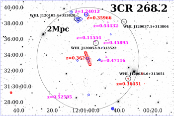
Figure 5. The SDSS R-band image of the field around 3CR 268.2 (Ahn et al. 2012). The radio contours of the LoTSS data set are marked in red as in Figure 9 to indicate the location of 3CR 268.2. Its redshift is also reported in red. The large dashed circle has a 2 Mpc radius computed at the central source redshift of 0.362 and centered on its position. Unrelated optical sources with spectroscopic redshifts are marked with magenta circles, and two with redshift differences less than 0.003 with respect to 3CR 268.2 are marked in red. Finally, black circles mark the location of the four candidate galaxy clusters found using photometric redshifts by Wen et al. (2012). Blue X-ray contours are drawn from the Chandra event file with a pixel size of 0984 and smoothed with a Gaussian kernel of 1378 at levels of 0.03, 0.05, and 0.07 photons. The candidate galaxy cluster WHL J120105.4+313828 at  in the northern direction appears to have an extended X-ray counterpart. The presence of sources at similar redshifts, as the one of 3CR 268.2, suggests the presence of a galaxy group surrounding it.
Download figure:
Standard image High-resolution image3CR 403.1 (z = 0.0554). We detected significant emission along and perpendicular to the radio axis. The extended X-ray emission is aligned with the gigahertz radio structure (see Figure 14); however, the TGSS structure is perpendicular to the X-ray extended emission, as shown in Figure 6. This could indicate the presence of a radio relic (see, e.g., Rottgering et al. 1994, 1997; Bagchi et al. 1998; Feretti & Giovannini 1998; Giovannini et al. 1999; Feretti et al. 2012; van Weeren et al. 2019).

Figure 6. Chandra image (exposure-corrected) in the 0.5–3 keV energy range and center-band energy of 2.3 keV with TGSS contours overlaid in black drawn at 0.025, 0.05, 0.125, and 0.75 Jy beam−1. The TGSS radio map has a beam size of 25''. The fact that the low-frequency radio emission is not cospatial with the X-ray emission suggests the presence of a radio relic.
Download figure:
Standard image High-resolution image
3CR 430 (z = 0.0555). We detected significant emission perpendicular to the radio axis (above a  level of confidence) that could be due to the ICM from a galaxy cluster at the same position as the radio galaxy. We additionally detected extended X-ray emission at 118'' (128 kpc at the source redshift) above the 5σ confidence level to the southeast of this source that could hint at the presence of another galaxy cluster, possibly undergoing a merging process with the former. Assuming this emission comes from the ICM from a galaxy cluster, the brightest cluster galaxy (BCG) would be J211836.50+604704.2, whose redsift is
  , which supports the hypothesis of these two galaxy clusters undergoing a merging process.
The left panel of Figure 7 shows an optical image of the field of 3CR 430 with radio (at 4.9 GHz) and X-ray (in the 0.5–3 keV band) contours. The right panel of Figure 7 shows the 0.5–3 keV Chandra image of 3CR 430 with TGSS contours overlaid. Diffuse radio emission lying beyond the extended X-ray emission could indicate the presence of a radio relic if the X-ray emission indeed arises from two merging galaxy clusters.
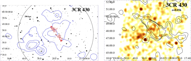
Figure 7. Left: Pan-STARSS optical image in the R band with VLA 1.4 GHz (in red) and Chandra 0.5–3 keV (in blue) contours of 3CR 430 overlaid. Radio contours were drawn starting at 0.2 mJy beam−1 and increasing by a factor of 2. The X-ray contours were drawn from the Chandra event file in the 0.5–3 keV energy range, smoothed with a 2952 Gaussian kernel at levels of 0.005, 0.08, and 0.1 photons and with 1968 pixels. The dashed black circle has a 200 kpc radius. The two different extended X-ray emission structures could indicate the presence of two galaxy clusters undergoing a merging process. Right: Chandra image with 0984 pixels, exposure-corrected in the 0.5–3 keV energy range at a center-band energy of 2.3 keV and smoothed with a Gaussian kernel of 1574 with TGSS contours overlaid in white drawn at 0.025, 0.05, 0.125, and 0.75 Jy beam−1. The TGSS radio map has a beam size of 25''. The TGSS contours mark the presence of radio emission unrelated to the extended X-ray emission, which could indicate the presence of a radio relic.
Download figure:
Standard image High-resolution image3CR 458 (z = 0.289). We detected extended X-ray emission 105'' (460 kpc at the source redshift) above a 5σ confidence level to the northwest of this source that could be due to the presence of another galaxy cluster possibly related to the radio galaxy (see Figure 15). Wen & Han (2015) reported the presence of a galaxy cluster at z = 0.407 at the position of the extended emission, which would mean that this extended emission would be unrelated to the radio galaxy (at z = 0.289). However, there is also another galaxy for which the photometric redshift is known at the position of this extended emission (Gorshkov & Konnikova 1995). This galaxy, at z = 0.29, would be consistent with a source belonging to the same galaxy cluster as 3CR 458.
5.3.1. X-Ray Surface Brightness Profiles
For sources with more than 100 photons along the radio axis (see Table 3), 3CR 18, 3CR 198, 3CR 287.1, and 3CR 332, we derived X-ray surface brightness profiles along and perpendicular to the radio axis. Images are shown in Figure 8, where the profile along the radio axis is represented on top of the one perpendicular to the radio axis, the extension of the radio emission is marked by a red vertical line, the blue dotted lines represent the hot-spot region, and the background level is indicated in orange. Although we only considered sources with the largest number of photons along the radio axis, the number of photons in each direction was still too low to obtain reliable results from the β-profile fit (Cavaliere & Fusco-Femiano 1976, 1978). Although we cannot distinguish thermal and nonthermal emission using β-profile fits, the X-ray surface brightness profiles show that the X-ray emission is extended at least up to the radio structure extent in all cases except for 3CR 198.

Figure 8. Surface brightness profiles for 3CR 18, 3CR 198, 3CR 287.1, and 3CR 332. The top profile in each panel corresponds to the profile along the radio axis, while the bottom profiles correspond to the profiles in the direction perpendicular to the radio axis. The orange points show the background level in each case. The red vertical line marks the extension of the radio emission along the radio axis, while the dashed blue lines mark the position of the hot spots. All sources, except for 3CR 198, seem to have X-ray emission extended at least as much as the radio emission.
Download figure:
Standard image High-resolution image6. A Multifrequency Perspective
6.1. Low Radio Frequency Observations
We compared our Chandra observations with low radio frequency observations from TGSS and LOFAR at ∼150 MHz. LOFAR observations were only available for 11 of our targets.
LOFAR observations are part of the forthcoming Data Release 2 (DR2) of LoTSS 32 , i.e., a deep 120–168 MHz imaging survey. These data sets were processed by the international LOFAR collaboration as part of the LOFAR Data Release 1 and 2 (Shimwell et al. 2017, 2019 and C. Tasse et al. 2021, in preparation, respectively).
Electrons responsible for IC/CMB emission from lobes in the soft X-rays (0.5–3 keV) are also responsible for the emission of synchrotron radiation at a frequency given by

where  is the observed frequency of the synchrotron radiation of the same electrons scattering the CMB at
  in the Thomson regime, B is the magnetic field in Gauss, and z is the source redshift. Then, considering
  ∼ 1017 Hz and
  μG (as found in the lobes of several radio galaxies by Ineson et al. 2017), we could detect synchrotron radiation from the same electrons emitting via IC/CMB in X-rays at radio frequencies of tens of megahertz. Therefore, using radio observations at ∼150 MHz allows us to get closer to the low-frequency regime needed to produce the IC/CMB radiation in the Chandra energy band. Thus, when we find low radio frequency lobe emission cospatial with the extended X-ray structure, we tend to favor a possible IC/CMB interpretation, if fainter or null cross-cone emission is present.
Sources for which LoTSS data were available are 3CR 18, 3CR 54, 3CR 198, 3CR 223.1, 3CR 268.2, 3CR 272, 3CR 313, 3CR 332, and 3CR 357. The LoTSS images are shown in Figure 9, where X-ray emission in the 0.5–3 keV band can be seen with VLA contours in blue and 150 MHz LoTSS contours in black overlaid. The X-ray and VLA image parameters are reported in Table 4, while the LoTSS image parameters are collected in the caption of Figure 9. In general, 150 MHz emission traces radio lobes along the whole radio axis, even where no high-frequency radio emission can be seen. The emission at 150 MHz matches the extent of the X-ray emission, which is in line with IC/CMB being the dominant emission process occurring cospatially with radio lobes.

Download figure:
Standard image High-resolution image
Figure 9. The X-ray image, VLA contours (cyan), and 150 MHz contours (black). The X-ray and VLA image parameters are shown in Table 4. The LoTSS contours for each source are at 40, 160, 640, and 1280 mJy beam−1 for 3CR 18; 10, 40, 160, and 640 mJy beam−1 for 3CR 54; 40, 80, 240, 640, 1200, and 1600 mJy beam−1 for 3CR 197.1; 2, 8, and 16 mJy beam−1 for 3CR 198; 10, 40, 160, and 640 mJy beam−1 for 3CR 223.1; 10, 40, 80, 160, and 640 mJy beam−1 for 3CR 268.2; 10, 40, 80, and 320 mJy beam−1 for 3CR 272; 10, 20, 80, 320, 500, 800, and 1300 mJy beam−1 for 3CR 293.1; 40, 160, 320, 640, and 1280 mJy beam−1 for 3CR 313; 10, 20, 40, 80, 160, and 320 mJy beam−1 for 3CR 332; 20, 40, 80, 160, and 320 mJy beam−1 for 3CR 357; and 100, 200, 800, 1200, and 2000 mJy beam−1 for 3CR 430. The LoTSS radio maps have beam sizes of 6''. The 150 MHz emission better traces the lobe emission than the gigahertz emission; thus, it suggests that the extended X-ray emission coincident with it is most likely due to IC/CMB from lobes.
Download figure:
Standard image High-resolution imageAll sources in our sample except 3CR 197.1 and 3CR 434 are extended in TGSS, but only 3CR 44, 3CR 135, 3CR 268.2, 3CR 272, 3CR 287.1, 3CR 313, 3CR 332, 3CR 357, 3CR 379.1, and 3CR 458 present a double morphology at ∼150 MHz. We only show the TGSS data of 3CR 103 (right panel of Figure 4), 3CR 403.1 (Figure 6), 3CR 430 (right panel of Figure 7), and 3CR 458 (bottom right panel of Figure 15), since we only used it to confirm the sources' double morphology.
6.2. An Optical Overview
We checked for the presence of "red sequences" (i.e., a color–magnitude relation followed by galaxies belonging to the same galaxy cluster; see Visvanathan & Sandage 1977; de Koff et al. 1996) in the fields of some sources in our sample to determine whether these sources belong to galaxy clusters. The sources selected were those for which the ratio of photons along and perpendicular to the radio axis  (Table 3), as defined in Equation (1), meaning that the emission perpendicular to the radio axis is comparable to the emission along the radio axis, which hints at the presence of thermal emission from the ICM in galaxy clusters. Magnitudes in the r and i bands (not corrected for Galactic absorption) for sources lying at >500 kpc radius around the positions of the radio galaxies were obtained from Pan-STARRS.
33
(Table 3), as defined in Equation (1), meaning that the emission perpendicular to the radio axis is comparable to the emission along the radio axis, which hints at the presence of thermal emission from the ICM in galaxy clusters. Magnitudes in the r and i bands (not corrected for Galactic absorption) for sources lying at >500 kpc radius around the positions of the radio galaxies were obtained from Pan-STARRS.
33
We explored the red sequences in the fields of 3CR 103 (since we detected extended emission in the field with no redshift information that could be related to the radio galaxy), 3CR 379.1, and 3CR 430. However, we were not able to identify red sequences in the fields of these sources. Nevertheless, spectroscopic follow-up observations would be crucial to confirm these results.
7. Summary and Conclusions
We carried out a thorough analysis of 35 FR II radio galaxies with angular sizes above 5'', measured in the gigahertz radio maps and observed during the 3CR Chandra Snapshot Survey before Cycle 20 but not in the 3CRR catalog (also excluding 3CR 187, 3CR 196.1, and 3CR 320, for which detailed follow-up analyses have already been performed). Our main goals were to
- 1.study how the presence of this extended emission affects the detection of hot spots and
- 2.investigate the origin of extended X-ray emission in radio galaxies (either nonthermal emission due to the IC/CMB from lobes or thermal emission from the ICM from galaxy clusters).
Throughout this analysis, we used 0.5–3 keV, background- and point-source-subtracted, exposure-weighted observations from the Chandra Snapshot Survey, refining the previous analyses.
We found that ∼90% of galaxies in our sample presented significant (>3σ confidence level) extended emission coincident with the radio axis (∼70% above a 5σ confidence level), while ∼60% presented significant extended emission in the direction perpendicular to the radio axis (∼40% above a 5σ confidence level). For those galaxies for which we detected extended X-ray emission perpendicular to the radio axis at similar confidence levels as the emission along the radio axis, we tend to favor the scenario where the underlying emission process is thermal radiation from an ICM, while for sources where no significant emission perpendicular to the radio axis is detected, we favor the scenario in which nonthermal IC/CMB emission is produced by electrons stored in the radio lobes.
In total, we found that IC/CMB is the most likely dominant emission process in ∼71% of our sources, while for ∼17% of them, the dominant emission process is most likely thermal emission from the ICM (see Table 3). However, we could not establish which mechanism was responsible for the extended X-ray emission in the remaining ∼11%. Among optically classified LERGs, for the same number of sources, the dominant emission comes from nonthermal (IC/CMB) and thermal (ICM) emission. For HERGs, nonthermal emission (IC/CMB) dominates in six times more sources than thermal emission (ICM). This suggests that FR II LERGs inhabit galaxy clusters more often than FR II HERGs (see Massaro et al. 2019, 2020 for an in-depth analysis of the environments of radio galaxies). A summary of these results can be found in Table 3.
We confirmed the detection of seven hot spots in the 0.5–3 keV band above the 3σ confidence level, excluding the possibility of them being fluctuations of the extended X-ray emission that surrounds them. Using the soft energy band and the local background, we did not confirm one of the detected hot spots claimed in previous survey analyses (n29 in 3CR 52) but do claim newly detected hot spots in two sources. This demonstrates the relevance of taking into account the extended emission along the radio axis when detecting hot spots. Additionally, we detected the presence of extended X-ray emission that could arise from the ICM in the fields of 3CR 103 and 3CR 430.
Using X-ray surface brightness profiles, we concluded that the X-ray emission is extended up to the extent of the radio structure in at least four sources. However, deeper X-ray observations are needed to distinguish between thermal and nonthermal emission processes.
We performed a multifrequency comparison to further constrain the origin of this emission. We compared low radio frequency and X-ray emission for sources with LOFAR observations (3CR 18, 3CR 54, 3CR 198, 3CR 223.1, 3CR 268.2, 3CR 272, 3CR 313, 3CR 332, and 3CR 357). In all cases, the low radio frequency morphology seems to trace the extended X-ray emission. Thus, in those cases, we tend to favor the IC/CMB as the dominant emission process. We performed an optical investigation of the red sequences of sources in the fields of 3CR 103, 3CR 379.1, and 3CR 430; however, it is not clear whether they belong to galaxy clusters/groups.
A summary of these results is presented in Table 3, where we show the number of photons in each region, with the number of background photons scaled to the size of the region in parentheses. The parameter ρ defines the ratio of the emission along and perpendicular to the radio axis scaled to the sizes of the regions according to Equation (1). We also collect in Table 3 information on sources that have newly detected hot spots, which ones are in known optical clusters, and which is the dominant emission process in each case.
Lastly, during this analysis, we made the serendipitous discovery that three hot spots in our sample were detected in WISE, namely, n22 in 3CR 69, s24 in 3CR 166, and n34 in 3CR 332. Additional details and images can be seen in Appendix B.
We thank the anonymous referee for useful comments that led to improvements in the paper.
We are grateful to G. Giovannini for providing insight into the radio emission of several radio galaxies.
This paper is based (in part) on data obtained with the International LOFAR Telescope (ILT). LOFAR (van Haarlem et al. 2013) is the Low Frequency Array designed and constructed by ASTRON. It has observing, data processing, and data storage facilities in several countries that are owned by various parties (each with their own funding sources) and collectively operated by the ILT foundation under a joint scientific policy. The ILT resources have benefited from the following recent major funding sources: CNRS-INSU, Observatoire de Paris, and Université d'Orléans, France; BMBF, MIWF-NRW, and MPG, Germany; Science Foundation Ireland (SFI) and Department of Business, Enterprise and Innovation (DBEI), Ireland; NWO, The Netherlands; the Science and Technology Facilities Council, UK; and the Ministry of Science and Higher Education, Poland.
The Pan-STARRS1 Surveys (PS1) and the PS1 public science archive have been made possible through contributions by the Institute for Astronomy; the University of Hawaii; the Pan-STARRS Project Office; the Max-Planck Society and its participating institutes, the Max Planck Institute for Astronomy, Heidelberg, and the Max Planck Institute for Extraterrestrial Physics, Garching; The Johns Hopkins University; Durham University; the University of Edinburgh; Queen's University Belfast; the Harvard-Smithsonian Center for Astrophysics; the Las Cumbres Observatory Global Telescope Network Incorporated; the National Central University of Taiwan; the Space Telescope Science Institute; the National Aeronautics and Space Administration under grant No. NNX08AR22G issued through the Planetary Science Division of the NASA Science Mission Directorate; National Science Foundation grant No. AST-1238877; the University of Maryland; Eotvos Lorand University (ELTE); Los Alamos National Laboratory; and the Gordon and Betty Moore Foundation.
A.J. acknowledges financial support (MASF_CONTR_FIN_18_01) from the Italian National Institute of Astrophysics under the agreement with the Instituto de Astrofisica de Canarias for the "Becas Internacionales para Licenciados y/o Graduados Convocatoria de 2017." This work is supported by the "Departments of Excellence 2018-2022" grant awarded by the Italian Ministry of Education, University and Research (MIUR) (L. 232/2016). This research has made use of resources provided by the Compagnia di San Paolo for the grant awarded on the BLENV project (S1618_L1_MASF_01) and the Ministry of Education, Universities and Research for grant MASF_FFABR_17_01. F.M. acknowledges the financial contribution from agreement ASI-INAF n.2017-14-H.0. A.P. acknowledges financial support from the Consorzio Interuniversitario per la Fisica Spaziale (CIFS) under the agreement related to grant MASF_CONTR_FIN_18_02. F.R. acknowledges support from FONDECYT Postdoctorado 3180506 and CONICYT project Basal AFB-170002. C.S. acknowledges support from the ERC-StG DRANOEL, No. 714245. R.K., W.F., and C.J. acknowledge support from the Smithsonian Institution and the Chandra High Resolution Camera Project through NASA contract NAS8-03060.
Appendix A: Tables and Images
Table 4 shows the parameters chosen for the images in Figures 10–15. These parameters are the radio frequency and contour levels for the radio emission and the pixel size and smoothing factors for the X-ray emission.

Figure 10. Chandra X-ray point-source-subtracted images (see Section 3) in the 0.5–3 keV band with VLA radio contours overlaid in black. The pixel sizes of all images, as well as frequency and contour levels, are reported in Table 4. (a) 3CR 18. The raw image shows a prominent readout streak originating from the bright nucleus. Extended X-ray emission is clearly detected in both directions, along and perpendicular to the radio axis. (b) 3CR 44. Extended X-ray emission is detected both perpendicular to and along the radio axis, the latter with higher significance. (c) 3CR 52. This source presents X-ray extended emission along and perpendicular to the radio axis. (d) 3CR 54. We detected extended X-ray emission in this source only along the radio axis. (e) 3CR 63. We detected extended X-ray emission in both directions, along and perpendicular to the radio axis. (f) 3CR 69. This source presents a relatively bright X-ray counterpart to the radio core. Additionally, the extended X-ray emission is mostly concentrated along the radio axis.
Download figure:
Standard image High-resolution image
Figure 11. Chandra X-ray point-source-subtracted images (see Section 3) in the 0.5–3 keV band with VLA radio contours overlaid in black. The pixel sizes of all images, as well as frequency and contour levels, are reported in Table 4. (a) 3CR 103. We detected extended X-ray emission along the radio axis and at ∼93'' in the southwest direction (see Section 5 for additional details). (b) 3CR 107. We detected extended X-ray emission only along the radio axis. (c) 3CR 114. This source has a relatively bright X-ray source associated with the radio core. It also shows extended X-ray emission in both directions, perpendicular to and along the radio axis, the latter with higher significance. (d) 3CR 133. We detected extended X-ray emission in both directions, perpendicular to and along the radio axis. Additionally, this is the only source in our sample with a double radio hot spot (to the east). (e) 3CR 135. We did not detect significant extended X-ray emission surrounding this source. (f) 3CR 165. We detected extended X-ray emission in both directions, along and perpendicular to the radio axis, although, due to the lack of radio core detection, it was not possible to perform the astrometric registration.
Download figure:
Standard image High-resolution image
Figure 12. Chandra X-ray point-source-subtracted images (see Section 3) in the 0.5–3 keV band with VLA radio contours overlaid in black. The pixel sizes of all images, as well as frequency and contour levels, are reported in Table 4. (a) 3CR 166. Extended X-ray emission is detected both perpendicular to and along the radio axis, the latter with higher significance. (b) 3CR 169.1. We detected extended X-ray emission only along the radio axis. (c) 3CR 180. We detected extended X-ray emission only along the radio axis. (d) 3CR 197.1. We detected extended X-ray emission in both directions, perpendicular to and along the radio axis. (e) 3CR 198. Extended X-ray emission is detected both perpendicular to and along the radio axis, the latter with higher significance, although, due to the lack of radio core detection, it was not possible to perform the astrometric registration. (f) 3CR 223.1. We detected extended X-ray emission only along the radio axis.
Download figure:
Standard image High-resolution imageTable 4. Image Parameters for X-Ray and Radio Emission
| 3CR | Radio Freq. | Beam Size | Contour | Pixel Size | Smoothing Gaussian |
|---|---|---|---|---|---|
| Name | (GHz) | (arcseconds) | Levels (mJy beam−1) | (arcseconds) | Kernel (arcseconds) |
| (1) | (2) | (3) | (4) | (5) | (6) |
| 18 | 1.4 | 1.70 | 5, 10, 20, 40, 80, 160, 320, 640 | 0.246 | 2.95 |
| 44 | 1.4 | 1.46 | 2, 4, 8, 20, 40, 80 | 0.492 | 5.90 |
| 52 | 1.4 | 3.59 | 10, 20, 80, 320, 640 | 0.984 | 9.84 |
| 54 | 8.0 | 0.40 | 0.2, 0.8, 3.2, 12.8, 51.2 | 0.492 | 6.89 |
| 63 | 1.4 | 1.36 | 1, 2, 4, 8, 16, 32, 64 | 1.968 | 23.62 |
| 69 | 4.8 | 5.00 | 2, 4, 8, 16, 32, 64 | 0.984 | 9.84 |
| 103 | 1.4 | 3.27 | 10, 20, 40, 80, 160, 320, 640 | 0.984 | 9.84 |
| 107 | 4.8 | 0.46 | 0.2, 0.4, 0.8, 1.6, 3.2, 6.4 | 0.123 | 1.48 |
| 114 | 1.4 | 1.27 | 2, 4, 8, 16, 32 | 0.246 | 3.44 |
| 133 | 1.4 | 0.98 | 8, 32, 64, 256, 512 | 0.123 | 1.48 |
| 135 | 8.0 | 0.66 | 0.02, 0.08, 0.32, 1.28 | 1.968 | 15.74 |
| 165 | 1.4 | 3.36 | 2, 8, 16, 32, 64 | 0.984 | 7.87 |
| 166 | 1.4 | 1.37 | 4, 8, 16, 32 | 0.492 | 3.94 |
| 169.1 | 1.4 | 1.37 | 2, 4, 8, 16, 32, 64 | 0.984 | 15.74 |
| 180 | 8.0 | 0.36 | 0.5, 0.7, 1, 2, 4 | 0.492 | 7.87 |
| 197.1 | 4.8 | 1.32 | 2, 3, 4, 5, 6, 8 | 0.492 | 3.94 |
| 198 | 4.8 | 25.9 | 1, 2, 4, 8, 10, 12 | 1.968 | 23.62 |
| 223.1 | 1.4 | 1.67 | 2, 4, 8, 20, 40, 80 | 0.492 | 3.94 |
| 268.2 | 1.4 | 1.61 | 2, 4, 8, 20, 40, 80 | 0.984 | 9.84 |
| 272 | 1.4 | 5.40 | 2, 4, 8, 20, 40, 80 | 0.984 | 9.84 |
| 287.1 | 1.4 | 5.00 | 2, 4, 8, 20, 40, 80 | 0.492 | 4.92 |
| 293.1 | 1.4 | 5.40 | 2, 8, 16, 32, 64 | 0.984 | 9.84 |
| 306.1 | 4.8 | 1.75 | 1, 2, 4, 8, 16 | 0.984 | 9.84 |
| 313 | 8.0 | 2.43 | 2, 4, 8, 32, 64, 128 | 0.984 | 11.81 |
| 332 | 1.4 | 4.40 | 2, 4, 8, 16, 32, 64 | 0.984 | 7.87 |
| 357 | 4.8 | 1.92 | 1, 2, 4, 8, 16 | 0.984 | 13.78 |
| 379.1 | 4.8 | 1.55 | 1, 2, 4, 8 | 0.984 | 11.81 |
| 403.1 | 0.3 | 7.03 | 16, 32, 64 | 0.984 | 13.78 |
| 411 | 1.4 | 1.30 | 4, 8, 16, 32, 64 | 0.123 | 1.48 |
| 430 | 4.8 | 1.34 | 1.5, 2, 4, 8, 16, 32, 64 | 0.984 | 15.74 |
| 434 | 1.4 | 1.40 | 4, 8, 16, 32, 64 | 0.246 | 3.44 |
| 435 | 4.8 | 1.76 | 1, 2, 4, 8, 16, 32 | 0.246 | 3.44 |
| 456 | 1.8 | 1.43 | 4, 16, 64, 256 | 0.123 | 1.72 |
| 458 | 1.4 | 6.40 | 2, 4, 8, 16, 32, 64 | 0.984 | 13.78 |
Note. Column descriptions: (1) source name; (2) radio frequency of contours in gigahertz; (3) beam size of the radio maps; (4) radio contour levels in millijanskys per beam; (5) pixel size of the X-ray image; (6) size of the Gaussian kernel used for smoothing the X-ray image.
Download table as: ASCIITypeset image
Images for all sources in our sample are shown in this section in Figures 10–15. We show their point-source-subtracted X-ray emission in the 0.5–3 keV band (as described in Section 3) with different pixel sizes and smoothing per source (see Table 4). Contours correspond to the radio emission at frequencies reported in Table 4.

Figure 13. Chandra X-ray point-source-subtracted images (see Section 3) in the 0.5–3 keV band with VLA radio contours overlaid. The pixel sizes of all images, as well as frequency and contour levels, are reported in Table 4. (a) 3CR 268.2. We detected extended X-ray emission only along the radio axis. Extended X-ray emission is detected at ∼302'' to the northeast of this source (see Section 5 for additional details). (b) 3CR 272. We detected extended X-ray emission only along the radio axis. (c) 3CR 287.1. Extended X-ray emission is detected both perpendicular to and along the radio axis, the latter with higher significance. (d) 3CR 293.1. We detected extended X-ray emission in both directions, perpendicular to and along the radio axis, the latter with higher significance. (e) 3CR 306.1. We detected extended X-ray emission only along the radio axis. (f) 3CR 313. Extended X-ray emission is detected both perpendicular to and along the radio axis, the latter with higher significance.
Download figure:
Standard image High-resolution image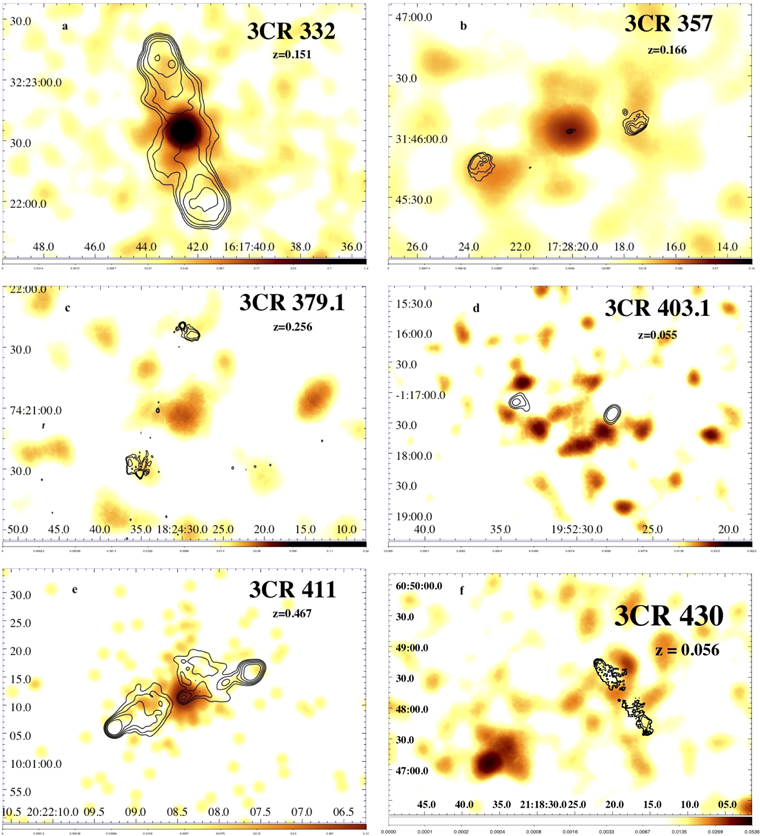
Figure 14. Chandra X-ray point-source-subtracted images (see Section 3) in the 0.5–3 keV band with VLA radio contours overlaid. The pixel sizes of all images, as well as frequency and contour levels, are reported in Table 4. (a) 3CR 332. Extended X-ray emission is detected both perpendicular to and along the radio axis, the latter with higher significance. The raw image shows a readout streak originating from the AGN nucleus. (b) 3CR 357. We detected extended X-ray emission only along the radio axis. (c) 3CR 379.1. We detected extended X-ray emission only perpendicular to the radio axis. (d) 3CR 403.1. We detected extended X-ray emission in both directions, perpendicular to and along the radio axis, the former with higher significance. However, the low-frequency radio structure is perpendicular to the gigahertz radio structure, which could indicate a radio relic (see Section 5 for additional details). (e) 3CR 411. Extended X-ray emission is detected both perpendicular to and along the radio axis. (f) 3CR 430. We detected extended X-ray emission only perpendicular to the radio axis. Additionally, we detected extended X-ray emission at ∼118'' to the southeast of this source (see Section 5 for additional details).
Download figure:
Standard image High-resolution image
Figure 15. Chandra X-ray point-source-subtracted images (see Section 3) in the 0.5–3 keV band with VLA radio contours overlaid. The pixel sizes of all images, as well as frequency and contour levels, are reported in Table 4. (a) 3CR 434. We detected extended X-ray emission only along the radio axis. (b) 3CR 435. There are actually two radio galaxies in this field, 3CR 435A to the northwest and 3CR 435B to the southeast. The astrometric registration was perfomed based on 3CR 435B. We detected extended X-ray emission in both directions, perpendicular to and along the radio axis, in both sources. (c) 3CR 456. Extended X-ray emission is detected both perpendicular to and along the radio axis, the former with higher significance. (d) 3CR 458. We also show the TGSS contours at levels of 40, 160, 640, and 2560 mJy beam−1 overlaid on the X-ray image in cyan. We detected extended X-ray emission only along the radio axis. Additionally, we detected extended X-ray emission ∼105'' to the northwest (see Section 5 for additional details).
Download figure:
Standard image High-resolution imageAppendix B: A WISE Serendipitous Discovery
We cross-matched the radio position of all hot spots in our radio galaxy sample with the AllWISE catalog, aiming at finding their mid-IR counterparts. This was done while performing the test on the mid-IR counterparts of X-ray sources detected using the wavdetect algorithm (see Section 3).
We adopted a search radius of 33, chosen on the basis of our previous analyses (see, e.g., D'Abrusco et al. 2013, 2014; Massaro et al. 2014), since the chance probability of having spurious cross-matches between radio sources with an average positional uncertainty of the order of ∼1'' and their potential WISE counterparts is less than ∼1% for angular separations below this value (see also Massaro et al. 2011a; D'Abrusco et al. 2012; Massaro et al. 2013a, 2013b, for additional information on the method of computing the chance probability).
We found three hot spots—namely, n22 in 3CR 69 (with W1 magnitude 15.553 ± 0.05), s24 in 3CR 166 ( ), and n34 in 3CR 332 (
 )—having a clear mid-IR counterpart, all detected at 3.4 and 4.6 μm in WISE images, as shown in Figure 16. The first two sources have an S/N greater than 15, while the third hot spot in 3CR 322 has an S/N of 13.9, all measured at 3.4 μm. These S/Ns are generally lower than those found, for example, for mid-IR counterparts of blazars with a radio flux density of the order of a few millijanskys (see, e.g., catalogs in D'Abrusco et al. 2014, 2019; de Menezes et al. 2019). Thus, although these S/Ns are well above the AllWISE catalog threshold,
34
we also carry out the following test to get a better idea of their significance. Since these hot spots have flux densities of the order of 1 mJy, we cross-matched all FIRST sources of 1 mJy (a total of 2907) with the AllWISE catalog within 33. We found a total of 1407 cross-matches, all unique. Then we found that 124 out of 1407 (i.e., ∼8%) have S/Ns between 13 and 16, and ∼one-third of all cross-matches are detected with S/Ns greater than 15, all computed at 3.4 μm, which is the band with the largest number of constraints to claim a mid-IR detection. Thus, we are confident that our claim on the discovery of mid-IR counterparts of three hot spots is reliable.
)—having a clear mid-IR counterpart, all detected at 3.4 and 4.6 μm in WISE images, as shown in Figure 16. The first two sources have an S/N greater than 15, while the third hot spot in 3CR 322 has an S/N of 13.9, all measured at 3.4 μm. These S/Ns are generally lower than those found, for example, for mid-IR counterparts of blazars with a radio flux density of the order of a few millijanskys (see, e.g., catalogs in D'Abrusco et al. 2014, 2019; de Menezes et al. 2019). Thus, although these S/Ns are well above the AllWISE catalog threshold,
34
we also carry out the following test to get a better idea of their significance. Since these hot spots have flux densities of the order of 1 mJy, we cross-matched all FIRST sources of 1 mJy (a total of 2907) with the AllWISE catalog within 33. We found a total of 1407 cross-matches, all unique. Then we found that 124 out of 1407 (i.e., ∼8%) have S/Ns between 13 and 16, and ∼one-third of all cross-matches are detected with S/Ns greater than 15, all computed at 3.4 μm, which is the band with the largest number of constraints to claim a mid-IR detection. Thus, we are confident that our claim on the discovery of mid-IR counterparts of three hot spots is reliable.
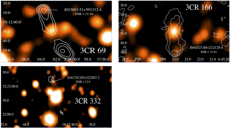
Figure 16. Top left: 3.4 μm WISE image of 3CR 69 with 4.8 GHz VLA contours overlaid. Radio contours start at 2 mJy beam−1 and increase by a factor of 4. The VLA radio map has a beam size of 5''. Top right: 3.4 μm WISE image of 3CR 166 with 1.4 GHz VLA contours overlaid. Radio contours start at 3 mJy beam−1 and increase by a factor of 4. The VLA radio map has a beam size of 137. Bottom: 3.4 μm WISE image of 3CR 332 with 1.4 GHz VLA contours overlaid. Radio contours start at 1 mJy beam−1 and increase by a factor of 4. The VLA radio map has a beam size of 44.
Download figure:
Standard image High-resolution image
It is worth noting that the mid-IR counterparts of hot spots and lobes of radio galaxies have already been observed in the past, especially for 3CR sources (Werner et al. 2012 and references therein). Our serendipitous discovery proves that WISE is also able to detect them with a shallow mid-IR survey. Additionally, one hot spot in our sample was previously detected in the literature in the optical and near-IR, namely, the eastern hot spot of 3CR 133 (Madrid et al. 2006). Lastly, de Koff et al. (1996) proposed a possible candidate for the optical counterpart of the western hot spot of 3CR 287.1.
Footnotes
- 21
- 22
- 23
- 24
- 25
- 26
- 27
- 28
- 29
- 30
- 31
- 32
The DR2 v2.2 was run as part of the ddf pipeline (https://github.com/mhardcastle/ddf-pipeline), and the LoTSS DR1 consists of images at 6'' resolution and ∼70 μJy beam–1 sensitivity covering an area of ∼400 deg2, while the footprint of the DR2 will cover an area of approximately 5700 deg2, both performed in the northern hemisphere.
- 33
- 34