
When an electric power system is stable, it can maintain stability against small disturbances. Small disturbances may include changes in load demand, fluctuations in renewable energy sources, or the sudden loss of a small generator. If the system is operating within an acceptable stable operation state, it should be able to withstand these small disturbances and return to its pre-disturbance state without significant issues. The system’s ability to do so is known as its small-signal stability [1, 2]. Using linearised models, small-signal stability analysis analyses the system’s response to small disturbances. This analysis can help identify potential stability issues and design appropriate control measures to prevent them.
It stimulates the specific process of each variable changing with time after the system disturbance. The time-domain simulation method is a commonly used method for existing stability research [3, 4]. Theoretically, only the exact model and parameters of the system are known; time-domain simulation can completely reproduce the changes in the existing system, so this method is often used as a validation tool for other analysis methods [5].
With the continuous response of governments of all countries to “environmental protection and green energy”, new energy power generation technology has become another new trend in the development of power grids [6, 7]. The continuous access to new energy grids has increased the complexity of power grids. The resulting new system stability problems have attracted the constant attention of power engineers conducting in-depth research. In recent years, many wind turbine off-grid accidents have occurred worldwide [8].
In essence, it emphasizes the importance of understanding the impact of reactive power control on the stability of wind farm grid-connected systems [9, 10, 11]. By analyzing sensor data, it is possible to identify the factors contributing to small disturbances in the design and develop strategies to mitigate them. This is important because small annoyances can escalate into significant system failures, causing damage to equipment and disruptions to the power supply [12, 13].
Scholars have conducted some preliminary studies on the slight disturbance: [14] analyzed the small disturbance stability and the impact of wind farms on the operating modes of nearby and remote generator sets through eigenvalue analysis. [15] have studied the system oscillation mode, but there is no inter-regional or local oscillation mode. [16] proposed a dynamic model of a wind turbine and simplified the controller design by decoupling the stator and control link. According to [17], through eigenvalue analysis, the relevant laws of the impact of wind farms’ total capacity and location on small disturbance stability are obtained. [18] discussed the simplified model further discussed, and [19] discuss the change rule of system frequency and damping of doubly fed wind turbines under different control strategies. [3] studied the impact of varying generator types, grid connection points and distributions on the grid’s stability. [6] analyzed the power system eigenvalue change rule under different permeability. After comparative analysis, they found that the doubly fed wind turbine has little impact on the system.
[7] proposed a voltage source control method suitable for the converter station at the sending end, which can solve the inertia loss and stability problems. Priyavarthini [12] points out that the circulating current in MMC will significantly increase the on-state loss in the converter. Given the above problems, a dual loop circulating current suppression strategy is proposed, which can substantially eliminate the double frequency. [14] established an equivalent model of MMC applicable to multiple working conditions, which can make MMC useful to various working conditions by adding controllers and control methods.
In conclusion, the influence of reactive power coordinated control based on sensor data analysis on small disturbance stability of wind farm grid connected system has been studied. However, its dynamic simulation model still needs to be further optimized and tested, which is also the focus of this paper.
This study identifies temporary synchronous stability issues and proposes an adaptive control method for wind turbines. It enhances turbine dynamics by controlling the inverter, addressing stability concerns across various scenarios. Experimental findings underscore the significant impact of small AC disturbances and minor DC faults. Comparatively, Modular Multilevel Converters-High Voltage Direct Current (MMC-HVDC) systems operate at higher frequencies and generate fewer low-frequency harmonics than Voltage Source Converters-High Voltage Direct Current (VSC-HVDC) systems, reducing the likelihood of inducing subsynchronous oscillations.
Figure 1 shows the converter topology of small disturbance stability of the wind farm grid connection system that includes a three-phase topology and submodule structure. It comprises six three-phase bridge arms, each with bridge arm inductance Larm and N interconnected SubModules (SM). Among them, the current of both the upper and lower bridge arms of phase j and Larm, the capacitance-voltage in SM, is said to be and bridge arm inductance. The summation of voltage on both the upper and lower bridge arms is the submodules of phase, and it denotes the Insulated Gate Bipolar Transistor (IGBT) trigger pulse in SM, DC voltage and DC [20].
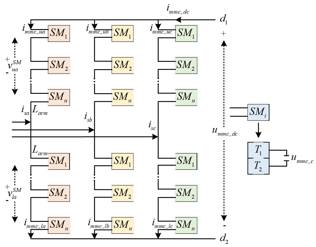
Assuming that the bridge arm sub-modules SM of MMC are relatively large, MMC can be regarded as continuous.
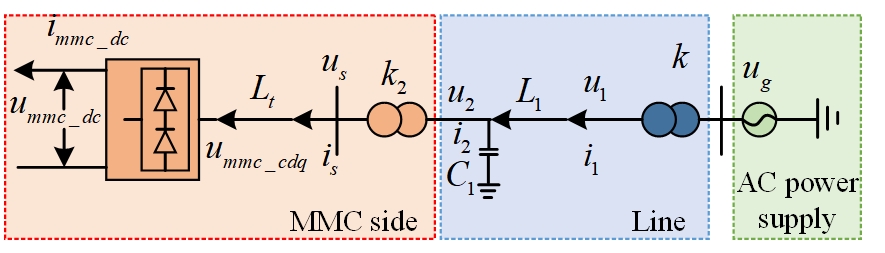
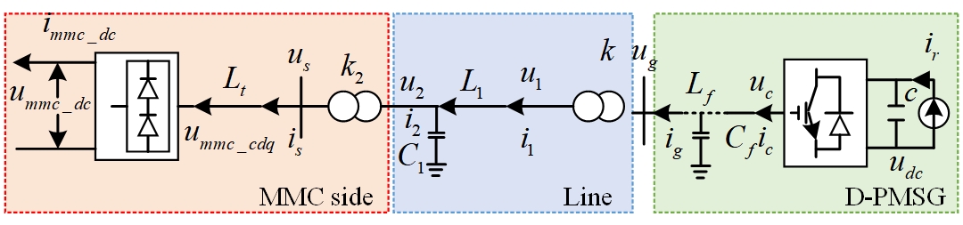
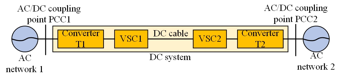
The working principle of the wind farm connected to MMC is shown in Figure 2, which includes two models. The first model works on processing the wind farm as an AC power source; then, it is connected to the MMC network-based connector station via a transmission line. The last green shaded box denotes the partial wind farm is changed by AC power supply and is boosted from 33KV to 230KV through transformation ratio k in the step-up transformer. Then it is connected to the transmission line, the blue box, presented in the middle area. It is boosted to 370KV through transmission ratio k2 in the step-up transformer; then it is connected to the MMC-HVDC grid side converter is represented in the last box.
Depending on the description of Eq. (1) to Eq. (4), the framework and controlling process of disturbance type and full power type of wind power grid-connected systems are different. However, the control objectives and control modes are in fault duration, mainly Low Voltage Ride Through (LVRT) control mode. Using this, the performance of all controllers is perfect. Hence, the principle of avoiding the dynamic features of the internal control loop and a single colossal signal equivalent circuit model can be recognized for various types of wind power grid-connected systems during the error occurred timing notification. Assumptions are as follows:
The output characteristics of simplified to the unified large signal equivalent circuit model as shown in Figure 3.
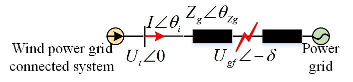
According to Figure 3, the generator under convention and the external characteristics of the wind power grid connected system. It can be expressed by the vector relationship of the three electrical quantities and line impedance voltage drop. Based on Kirchhoff’s voltage law, the vector relationship is shown in Eq. (1).
\[\label{eq1}\tag{1} {{U_t} = I{Z_g} + {U_{gf}}}.\]
Depending on assumptions, the optimized expression as Eq. (2) and Eq. (3):
\[\label{eq2}\tag{2} {{\theta _{\text{i}}} = \arctan \left( {{I_q}/{I_d}} \right)},\]
\[\label{eq3}\tag{3} {{\theta _{{\text{zg}}}} = \arctan \left( {{X_g}/{R_g}} \right)}.\]
In the present situation, Figure 4 describes the need for transformation (i.e.) transform the variable coefficient differential equations into the constant coefficient differential equations through rotation coordinate transformation. Assume the generator windings have a three-phase symmetrical, the magnetomotive force is sinusoidal, the magnetic circuit is unsaturated and the winding inductance is linear, the ferromagnetic loss is ignored, and the winding temperature rise effect is avoided.
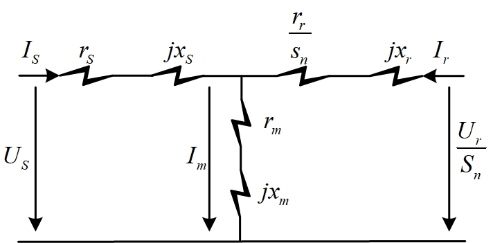
Its equivalent expression is defined in Eq. (4) and Eq. (5):
\[\label{eq4}\tag{4} {{u_{sd}} = – \frac{{d{\psi _{sd}}}}{{dt}} – {\omega _s}{\psi _{sq}}},\]
\[\label{eq5}\tag{5} {{u_{_{sq}}} = – \frac{{d{\psi _{_{sq}}}}}{{dt}} + {\omega _s}{\psi _{sd}}}.\]
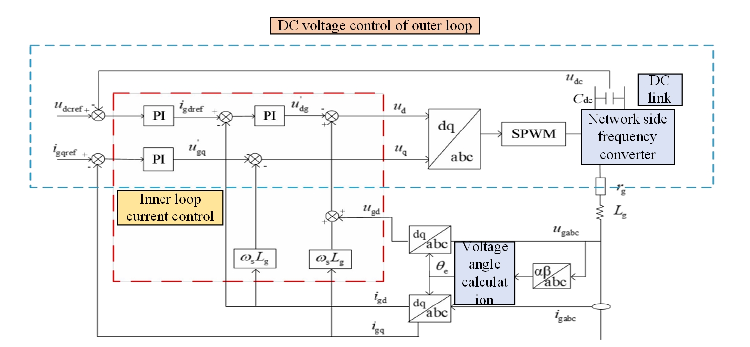
These devices consume a certain amount of active power and cause reactive power loss during operation. The presence of DFIG in wind farms has the capability of reactive power regulation and does not depend on any compensations. At the same time, the link capacitor voltage of DC may be stable for some time by creating the current variations between the two to 0 constant via real-time adjustment. The detailed control strategy is a double closed-loop structure, as shown in Figure 5.
The relationship between the transmission power is given in Figure 6. When the X/R value of the line is low, the active power affects the time variation, and if it is not controlled, then the fluctuation occurs in the system voltage. When the X/R value of the line is high, the reactive power affects the high voltage side.
The disconnection of one unit can cause other units to work abnormally, which may lead to the disconnection of different wind turbine units, thus expanding the scope of the accident and bringing a tremendous hidden system. In addition, the disconnection accident is a complex evolution process that lasts for a long time, which can be thoroughly studied and explained by the analysis mechanism of power system dynamic stability or small disturbance stability. Due to these issues, this article is mainly concentrated on discussing the following three factors that may affect the small disturbance power systems, preliminarily discussing the generation mechanism of grid disconnection accidents.
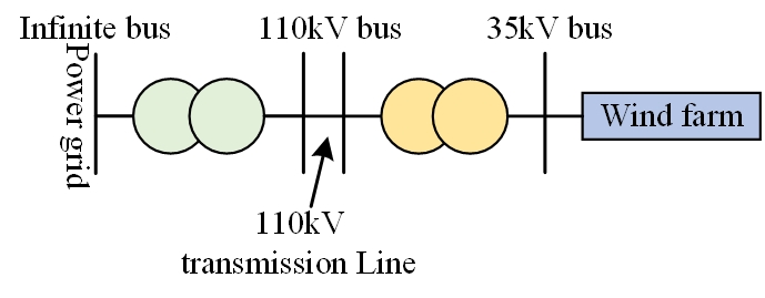
Tightness of connection between wind farms and large systems Large wind farms under construction in China are generally. In the past stability analysis, large wind farms often used one or several equivalent machines to consider, as shown in Figure 7.
Two systems and eigenvalue analysis method are used to study the influence of the above three factors, as shown in Figure 8 and Table 1.
| Parameters | Values |
| Parameters of doubly fed generator | \(P_N\)=1.5MW, \(V_N\)=690V, \(f\)=50Hz, \(R_S\)=0.00708p.u., \(X_S\)=0.0225p.u., \(R_r\)=0.02p.u., \(X_r\)=0.1p.u.,\(X_m\) =4p.u., \(p\)=2, \(J=95kg.m^2 \) |
| Wind turbine parameters | \(H_tw\)=3s, \(H_gen\)=0.5s, K=10, D=3.16, R36m, \(V_m\)=11m/s,\(T_servo\) =0.5s |
| Transmission line parameters | 35kV transmission line: \(R=0.38 \Omega/km\), \(X=0.4003\Omega/km\).110kV transmission line: \(R=0.045 \Omega/km\), \(X=0.13.84\Omega/km\) |
Using the above system parameters, the study on the change rule of the system using eigenvalues includes the connecting lines output and wind farms. The results are shown in Table 2, and the corresponding eigenvalue change track is shown in Figure 9 and it shows the impact of reactive power coordination control on small disturbance stability of grid connected wind farm system based on sensor data analysis [16, 17].
| S.No | 10km | 15km | 20km | 30km | 50km | 80km | 100km | 120km |
| 1 | -5.68±j13.868 | -5.636±j13.978 | -5.601±j14.088 | -5.55±j14.438 | -5.322±j14.544 | -4.331±j13.165 | -4.313±j13.371 | -4.263±j13.588 |
| 2 | -5.615±j13.637 | -5.594±j13.744 | -5.566±j13.853 | -5.496±j14.071 | -5.344±j14.804 | -4.624±j13.062 | -4.621±j13.275 | -4.586±j13.508 |
| 3 | -1.994±j13.326 | -1.991±j13.327 | -1.992±j13.333 | -1.986±j13.333 | -1.974±j13.333 | -1.958±j13.333 | -1.944±j13.325 | -1.933±j13.317 |
| 4 | -1.953±j13.411 | -1.954±j13.412 | -1.952±j13.413 | -1.942±j13.414 | -1.931±j13.414 | -1.918±j13.414 | -1.903±j13.404 | -1.896±j13.398 |
| 5 | -1.901±j13.758 | -1.897±j13.755 | -1.898±j13.747 | -1.888±j13.744 | -1.875±j13.723 | -1.766±j13.713 | -1.662±j13.672 | -1.593±j13.717 |
| 6 | -1.904±j13.674 | -1.891±j13.666 | -1.875±j13.635 | -1.857±j13.627 | -1.802±j13.615 | -1.623±j13.566 | -1.556±j13.616 | -1.516±j13.706 |
| 7 | -1.898±j13.647 | -1.888±j13.643 | -1.881±j13.666 | -1.865±j13.658 | -1.816±j13.645 | -1.722±j13.645 | -1.706±j13.738 | -1.673±j13.776 |
| 8 | -1.892±j13.986 | -1.893±j13.983 | -1.888±j13.976 | -1.881±j13.972 | -1.873±j13.953 | -1.853±j13.922 | -1.835±j13.896 | -1.823±j13.865 |
| 9 | -1.841±j13.544 | -1.833±j13.545 | -1.817±j13.543 | -1.796±j13.535 | -1.732±j13.533 | -1.577±j13.505 | -1.486±j13.584 | -1.445±j13.697 |
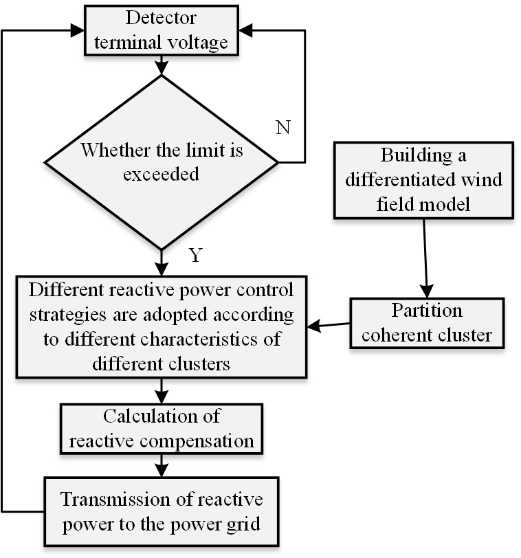
Therefore, this paper adopts a coordinated reactive power, in which the chemical groups in the wind farm are first coherently divided and then controlled according to the actual operating characteristics of different clusters. The technical system strategy divides the units with similar operational characteristics and is formed as clusters, as shown in Figure 10.
The first step is to collect the operating data of the sub synchronous oscillation phenomenon and then feed the operational data into a doubly-fed wind farm. The WFMMC impedance model is recognized to claim the calculated values. The corresponding impedance frequency response curve can be obtained using the calculated values.
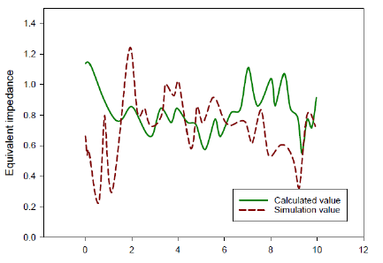
In the second step, a slight disturbance current signal in WFMMC models occurs at different frequencies, which can be obtained through the calculation formula of small disturbance impedance values. The corresponding impedance frequency response curve can be obtained based on calculated simulation values. According to the calculation formula of small disturbance impedance value, as shown in Figure 11.
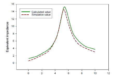
Figure 12 shows the RSC current inner loop proportional parameter kpr changes when the different current inner loop proportional parameters action exists. It increases the 9s after a period of stable output, peaks at about 9.7s, and the reactive power starts to increase at about 9s. When the kpr rises to 5, the fluctuation period is about 2s, and the peak amplitude shows an increasing trend. The time when the reactive power fluctuation amplification trend appears is advanced, and the fluctuation trend starts to show a growing trend of about 7s.
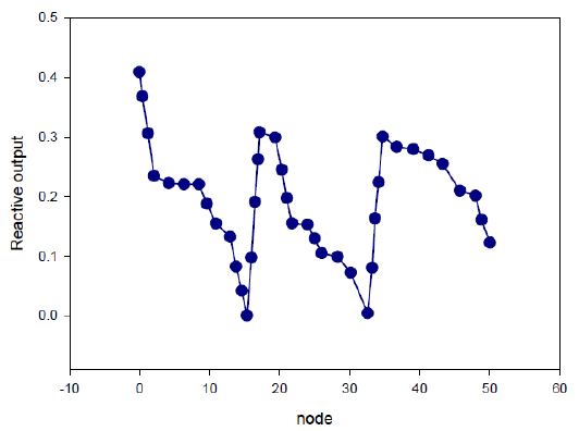
Compare two cases: DFIG unified compensation; DFIG decentralized coordination control compensation capacity. When conducting DFIG unified compensation, make all DFIG output reactive power the same, and cooperate with SVC and OLTC to build a reactive power and voltage optimization simulation model. When DFIG decentralized coordinated control is carried out, each fan is used as an independent reactive output variable to cooperate with SVC and OLTC to build a reactive power and voltage optimization simulation model. The above two cases are solved respectively according to the LinWPSO algorithm. The reactive power optimization voltage results are shown in Table 3, each node is shown in Table 4, and the reactive power output of each DFIG is shown in Figure 13 when the DFIG topology is used for decentralized coordination control of compensation capacity [21].
| Index | DFIG unified compensation | DFG decentralized coordinated control compensation |
| Active network loss/MW | 0.475 | 0465 |
| Total voltage deviation (p.u.) | 1.6782 | 0.9757 |
| SVC reactive/MVar | 2.2045 | 1.0133 |
| OLTC transformation ratio | 110Kv-2×1.25%/35k | 110 kV/35k |
In the case of DFIG unified compensation, the active network loss of the wind farm is 0.473MW. In the case of decentralized coordinated control based on DFIG topology, the functional network loss of the wind farm is 0.467MW. At present, the active network loss optimization is noticeable and economical. The unit of uniformly compensated DFIG is 1.6780, and the unit of decentralized and coordinated DFIG is 0.9759. At present, the wind farm adopts the constant power factor control mode. However, each DFIG should not adopt the constant power factor control mode. Instead, it distributes reactive power according to its topology to achieve decentralized coordinated control [2].
To sum up, as the proportional parameter kpr of the RSC current inner loop continues to increase, the electromagnetic torque oscillation frequency of the wind turbine generator continues to decrease, and the system presents a negative damping characteristic in the 38-42Hz frequency range. As the proportional parameter kpr increases, the negative damping characteristic area moves to the left. The larger the proportional parameter kpr, the more pronounced the negative damping characteristic, the more unstable the wind farm grid.
| Time interval | Active network loss/MW | Total voltage deviation (p.u.) | SVC reactive/MVar | OLTC transformation ratio |
| 1 | 0.177 | 1.2956 | 0.3152 | 110kV+2×1.25%/35k |
| 2 | 0.387 | 1.2343 | 0.6917 | 110kV+1×1.25%/35k |
| 3 | 0.868 | 0.6772 | 0.2907 | 110kV+1×1.25%/35k |
| 4 | 0.897 | 0.6576 | 0.2132 | 110 kV/35k |
| 5 | 0.828 | 0.9936 | 0.1744 | 110 kV/35k |
| 6 | 0.345 | 1.0675 | 0.1015 | 110 kV/35k |
| 7 | 0.183 | 1.2083 | 0.4106 | 110kV+1×1.25%/35k |
| 8 | 0.163 | 1.4566 | 0.5697 | 110 kV/35k |
| 9 | 0.163 | 1.0793 | 0.9919 | 110kV-1×1.25%/35k |
| 10 | 0.166 | 1.1255 | 0.4203 | 110kV+1×1.25%/35k |
| 11 | 0.144 | 1.0767 | 0.9867 | 110kV-2×1.25%/35k |
| 12 | 0.147 | 1.1434 | 0.4252 | 110kV+1×1.25%/35k |
| 13 | 0.144 | 1.0599 | 0.9928 | 110 kV/35k |
| 14 | 0.144 | 1.1495 | 0.4252 | 110kV+1×1.25%/35k |
| 15 | 0.156 | 1.4786 | 0.5697 | 110 kV/35k |
| 16 | 0.157 | 1.2087 | 0.0672 | 110kV-1×1.25%/35k |
| 17 | 0.141 | 1.2266 | 0.3102 | 110kV+2×1.25%/35k |
| 18 | 0.165 | 1.1522 | 0.6937 | 110kV+1×1.25%/35k |
| 19 | 0.177 | 1.1151 | 0.6173 | 110 kV/35k |
| 20 | 0.163 | 1.0391 | 1.0367 | 110kV-1×1.25%/35k |
| 21 | 0.264 | 1.1807 | 0.4446 | 110kV+1×1.25%/35k |
| 22 | 0.583 | 1.3266 | 0.4857 | 110 kV/35k |
| 23 | 0.876 | 0.6085 | 0 | 110kV-1×1.25%/35k |
| 24 | 0.888 | 0.6762 | 0.0258 | 110 kV/35k |
In recent years, with the rapid growth of grid-connected modes such as wind power generation, more and more people have paid attention to the optimization requirements of algorithms for grid-connected wind power generation. Based on the wind farm’s responsiveness and control allocation principle, the optimization model is established by combining SVC and Voltc. At the same time, considering the impact of the increase of wind power on the energy storage system, the best mode of the wind farm and grid energy storage system is set. The experimental results show that to provide responsiveness for the energy system, reduce the changes in the responsiveness of the wind farm, and improve the responsiveness of the wind farm, coordinated responsiveness is a strategic observation of the wind turbine. Further, the dynamic equivalence method of large wind farms composed of doubly-fed wind turbines is preliminarily studied.
This study is supported by General Program of NSFC (61771008).
The authors declare no conflict of interests.